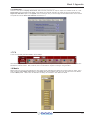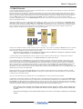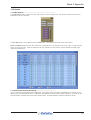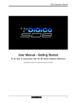
1
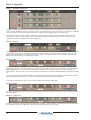
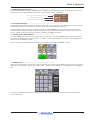
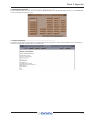
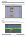
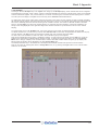
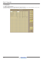
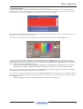
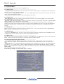
Mach 3 Appendix
New Features Appendix
User Manual for Software Versions 4.0.523+
1-1
Mach 3 Appendix
1-2
Mach 3 Appendix
Contents
1.1 Channel Functions .................................................................. .......1-5
1.1.1 Input Channel Meters .................................................... .......1-5
1.1.2 Channel Aux Send Panel .............................................. .......1-5
1.1.3 DiGiTube Warmth ........................................................... .......1-5
1.1.4 Signal Processing ......................................................... .......1-6
1.1.5 Buss Routing Indication ............................................... .......1-9
1.1.6 Channel Ganging ........................................................... .......1-9
1.1.7 2nd Function & Hard Mutes .......................................... .......1-9
1.1.8 Delay Units ..................................................................... .......1-9
1.2 System Menu .......................................................................... .......1-10
1.2.1 Clear Overview ............................................................. .......1-10
1.3 Files Menu ............................................................................... .......1-10
1.3.1 Templates ..................................................................... .......1-10
1.3.2 Session Structure ........................................................ .......1-10
1.3.3 GPI/GPO ........................................................................ .......1-10
1.3.4 Set Global Defaults ...................................................... .......1-11
1.3.5 Session Report ............................................................ .......1-11
1.4 Layout Menu ........................................................................... .......1-12
1.4.1 Channel List ................................................................. .......1-12
1.4.2 Set Spill ......................................................................... .......1-13
1.5 Snapshots ............................................................................... .......1-14
1.5.1 MIDI command display ................................................ .......1-14
1.5.2 Snapshot Notes ........................................................... .......1-15
1.6 Options Menu ......................................................................... .......1-16
1.6.1 Surface tab: .................................................................. .......1-16
1.6.2 Faders tab: ................................................................... .......1-16
1.6.3 Delays tab: ................................................................... .......1-16
1.6.4 Disable tab: .................................................................. .......1-16
1.6.5 Meters tab:.................................................................... .......1-16
1.6.6 Console tab (formerly Session tab): .......................... .......1-16
1.6.7 Status tab: .................................................................... .......1-17
1.7 FX ............................................................................................. .......1-17
1.8 Matrix ....................................................................................... .......1-17
1.9 Graphic EQ.............................................................................. .......1-18
1-3
Mach 3 Appendix
1.10 Setup Menu ........................................................................... .......1-18
1.10.1 New Rack Types ........................................................ .......1-18
1.10.2 Macros ........................................................................ .......1-18
1.11 Multi Channels ...................................................................... .......1-19
1.11.1 Edit Multi ..................................................................... .......1-20
1.12 Auxes ..................................................................................... .......1-21
1.12.1 Mix Presets ................................................................. .......1-21
1.12.2 CG Faders Control Aux Sends ................................. .......1-21
1.13 Meters .................................................................................... .......1-22
1.14 Miscellaneous Changes ..................................................... .......1-23
1.14.1 Overview Screen ........................................................ .......1-23
1.14.2 List navigation ........................................................... .......1-23
1.14.3 Offline Software ......................................................... .......1-23
1-4
Mach 3 Appendix
IMPORTANT NOTE:
Sessions saved with software versions V500+ will not be able to be loaded into any earlier versions.
1.1 Channel Functions
1.1.1 Input Channel Meters ...........................................................
A new meters panel can be displayed over the input and filters modules at the top of input channel strips. To do this, press the
assign up button, located to the left of the encoders above the screen. If these encoders are initially assigned to the trim function, you will need to press the assign up button (Scroll up/down) twice to display the meters.
1.1.2 Channel Aux Send Panel ....................................................
It is now possible to show all of the aux sends for a channel in a single display and assign them to the rotaries beneath the
screen. This is done by touching the currently assigned aux row on the screen for the channel that you want to display. The
layout of the display indicates which encoder each aux is assigned to; if there are more sends than physical controls, the
assignments becomes scrollable using the Screen Scroll function.
Once you have adjusted the auxes in this display, you need to close it manually before opening any other channel detail display.
1.1.3 DiGiTube Warmth .................................................................
Channel Setup panel now has a Warmth button next to the DiGiTube On switch. If Warmth is pressed, the DiGiTube controls are
set to their defaults, hidden, and switched on. Warmth is hidden if DiGiTube is switched on instead. DiGiTube controls are hidden
automatically if the console’s permitted maximum are already used up.
1-5
Mach 3 Appendix
1.1.4 Signal Processing .................................................................
Q Shapes
Channel EQ now has Precision and Classic buttons which affect the Q shape of each band, switching what was previously
Reciprocal and Symmetrical, respectively. On each band, the bell button's 2nd function switches between prec (precision,
where the Q is narrower on the cut curve than the boost curve) and class (classic, where the cut and boost Q curves are
identical in width). The active setting is shown in red to the right of the bell button. Pressing the precision or classic buttons
above the EQ controls will switch all four visible bands to that shape. The active button goes blue – if different bands are employing different shapes, neither button will be blue.
Filter value displays
Filter frequencies are now displayed as the –3dB value instead of –6dB.
Dynamic EQ indication
The small EQ Graph in the channel strip now has coloured indicators for each band of Dynamic EQ. They go grey if the band is
switched off.
EQ and filters
both off
EQ off,
filters on
EQ on,
Filters off
Dynamic EQ on Dynamic EQ on
bands 2+4, with band 2+4, with
both bands off
both bands on
It is not now also possible to switch the band off without Dynamic EQ active.
Dynamics links
Stereo Groups and Auxes can now have their Dynamics Link switched off if required. When on, it links only the Left and Right
legs.
Multiband band bypass
The MultiBand Compressor band on/off is now implemented as a bypass instead of a mute.
1-6
Mach 3 Appendix
Dynamics module options
There are now three types of dynamics processor for each of the two dynamics modules. Module 1 is a fully configurable
compressor which can be split into three frequency bands or configured as a de-esser; Module 2 can function as a gate, a
ducker, or a compressor, all with high- and low-pass filtering.
The in-channel display is located below the eq display, with Module 2's controls shown below Module 1's. Each module can be
switched on by pressing the COMP (Dyn 1) or Gate (Dyn 2) on/off switch on the console worksurface. The associated on screen
buttons are grey when off and red when on.
The display includes an input (In) meter and a gain reduction (GR) meter. The input meter has arrows to its right which display the
current threshold values for each module. Each arrow is distinguished by its colour, which matches its associated threshold pot.
When Module 1 is in Compressor or Multiband mode, threshold and gain pots, each with a value display in dB, are also shown in
the channel strip (when in Multiband mode, the threshold pot affects all bands and the mid band's value is displayed). The Deesser only displays a theshold pot and its value. There is a threshold pot (with value display) shown for Module 2, with three
status indication lights shown when in Gate or Ducker mode.
1: Compressor
2: Gate
1: Multiband
2: Ducker
1: De-esser
2: Compressor
Pressing anywhere in either module area brings up the expanded dynamics display.
To switch each module between its three modes, touch the button on the left of its expanded display, marked comp/multi/
desser for Module 1, and gate/duck/comp for Module 2. Both modules can be switched on using the on button below their
threshold buttons. The joint input meter is shown in the expanded display, with the same threshold indication. In multiband
channels, each component has its own meter.
The pots within the expanded display are automatically assigned to the worksurface encoders below the screen when the
dynamics panel is expanded, as indicated by the matching coloured rings around the pots and encoders. When in Multiband mode,
each band is assigned to a row of encoders. When Module 2 is also on, it appears in the bottom row of encoders.
Note that if the gate occupies the bottom row of encoders while the multiband compressor is on, the HF compressor
band is not displayed, and the MF and LF bands both shift up a row.
At the top of the expanded display are buttons marked safe and presets. Touching safe adds the dynamics to that channel’s list
of channel safes. Touching preset brings up the Presets display which can be used to save and recall presets.
If a link button is shown below the input meter, it allows two channels to be linked together. In other words, the other channel's
signal is added to this compressor’s control circuit input, and this channel’s signal is added to the other channel’s control input.
On stereo input channels, the link is always active and the button isn't shown. On stereo output channels, the link button is
available and the link is always between left and right components; it is active by default.
On mono or multiband channels, pressing this button brings up a dynamics link display listing Channels, Groups and Auxes
signal groups in the left-hand side. When one of these signal groups is selected, their available signals are listed in the righthand side of the display. Select a signal to link to and close the display.
The link button is ringed red and the linked channel’s number and name is displayed in the box above it to indicate that there is a
link present. To cancel the link, press the button again and deselect the link signal.
Note that when a link channel has no name, the display repeats the channel number.
Beyond the link function, the different modes of each module have completely separate settings: No settings are copied between
them. If you switch from one mode to the other, the settings will be reset to their defaults. The controls specific to each mode of
each module are described below:
Module 1: Compressor
In Module 1's compressor, threshold, attack, release, ratio and gain controls are provided, each of which function in the
normal way. The compressor has an auto gain function which is switched on by pressing the auto gain button below the ratio
pot. This function automatically adjusts the gain makeup when changes are made to the threshold, thus keeping the compressor
output steady. The threshold knee can be switched between hard, mid and soft using the knee button in the right side of the
module. The gain reduction (GR) meter is duplicated in this display.
1-7
Mach 3 Appendix
Module 1: Multiband Compressor
In Module 1's multiband compressor, each band includes all of the parameters found in the single band compressor. The link
function remains available for the whole compressor, and is not assigned to any band. The bands can be switched on individually
using the on buttons in the left-hand side of each band, or together using the all on button in the display’s right.
The crossover frequency between bands is controlled using the purple and red pots to the left of the hi and lo bands. Each
crossover has a range of 20Hz to 20kHz, and the crossover frequencies are displayed below each pot. Each band can be
auditioned by pressing the listen button below each gain pot.
Module 1: De-esser
The de-esser's controls are similar to those of the compressor, with the following exceptions: In the right side of the module, there
is a band-pass filter control for the de-esser sidechain, with pots provided for the centre frequency and filter width. The -3dB
points for the hi-pass (hp) and lo-pass (lp) frequencies are shown. The filtered sidechain can be auditioned by pressing the
listen button. Note that there is no make-up gain included.
Module 2: Gate
Gates can be keyed by a different signal by pressing the key button below the attack pot. This brings up a Gate Key Route
display from which a key input can be selected. Consecutive channel gates can be keyed by consecutive input signals using the
ripple channels function. The key button is ringed red and displays the key input in the text box to its right to indicate that
another signal is keying the gate. The key input signal can be auditioned by pressing the key listen button underneath the range
pot.
There is a band-pass filter available: the width control adjusts the width of the band being passed, and the freq control moves
that band through the frequency range. The hi- and lo-pass sidechain filter frequencies are displayed.
To the right of the link button, there are red, amber and green status indication 'traffic lights'.
Module 2: Ducker
The ducker has exactly the same controls as the gate, though the sidechain performs the opposite function of ducking the signal
rather than gating it.
Module 2: Compressor
Module 2's compressor is identical to the single band mode of Module 1, with the addition of the band-pass filter described above,
and a sidechain input function (S/C) which functions exactly like the key function of the gate.
1-8
Mach 3 Appendix
1.1.5 Buss Routing Indication .......................................................
The Buss Routing section of channel Output panels now highlights the buss type buttons down the left to show that some are
routed to even if not currently displayed. This applies to input channels, groups, and talkback.
Unlit:
mono routing inactive and not shown
Lit:
stereo groups shown to right
Half lit: 5.1 routing active but hidden
1.1.6 Channel Ganging ..................................................................
Channel Undo now undoes an action for the whole of a gang, multi or surround output. When any member of those is Assigned,
all subsequent changes on any member will undo back to the state when the assignment was made.
It is now possible to gang channels across different surfaces by selecting GANG on the LCD menu on all required surfaces
before selecting the first gang member. When the first member is selected, all surfaces waiting for a gang to join will now join
that one. Starting a new gang still works as before by reselecting the GANG LCD function.
1.1.7 2nd Function & Hard Mutes ..................................................
The surface HARD mute buttons now flash bright-to-dim when hard mute is on, and 2nd Function does not alter the mute lights
even though the buttons will only affect hard mutes in this state. The hard mute indicator on the screen is now highlighted with a
white box when 2nd Function is active.
There is now a green indicator shown at the bottom left of channel screens when 2nd Function is active:
1.1.8 Delay Units ............................................................................
Delays can now be entered in seconds, feet, metres or beats-per-minute. Extra buttons added to the side of the numeric keypad
sets these for input channels, outputs, FX and matrix inputs. They can also be changed in the new Delays tab of the Options
menu.
The coarse and samples delay rotaries have been added to output setup panels, to allow access to the numeric keypad and
choice of delay units.
1-9
Mach 3 Appendix
1.2 System Menu
1.2.1 Clear Overview .....................................................................
The Overview Clear Screen button in the System menu now has a confirm stage.
1.3 Files Menu
1.3.1 Templates ..............................................................................
A new Session Templates button at the top of the Files menu displays a form which lists (ordinary) session files in the folder
d:\Templates, or c:\Templates if not on a console. This folder should be created manually and have the required template sessions
copied into it.
NOTE: Sessions can only be put into the Templates folder using Windows Explorer - this cannot be done from the SD application.
If you create a Template session, save it as normal in the D:\Projects folder and then Quit To Windows, right click on the Start
button and choose Explore. Now navigate to D:\Projects and copy the relevant file to the D:\Templates folder. This procedure will
ensure that your Template cannot be easily overwritten in normal operation.
1.3.2 Session Structure ..................................................................
Session Structure panel aux order and group order buttons are now found on all consoles. These open further configuration panels where aux and group channel lists can be edited and reordered.
There is a new option to build banks horizontally or build banks vertically on restructure. Rebuilding horizontally will result
in input channels being spread across the top layer of both sides of the console, using as many banks as required, with output
channels being assigned to Layer 2. Rebuilding vertically will result in input channels being assigned to Layer 1 on the left side of
the console, and output channels to Layer 1 on the right. See the Session Structure section of Chapter 3 for more details.
1.3.3 GPI/GPO ................................................................................
There is a new GPIO Relays button in the System menu, which opens a panel displaying the current GPI and GPO states. The 16
numbered 'out:' buttons allow GPOs to be triggered. If the toggle button above them is active (lighter), then touching a GPO
button will switch it on (red) or off (brown). If the pulse button is active, touching a GPO button will send an 'on' pulse.
Note that GPOs which are on when entering pulse mode will stay on. Touching them while in pulse mode will switch them
off.
The GPI event light in the top right-hand corner indicates when GPI messages arrive. Below the GPO buttons is a row of
indicators (labelled 'in:') showing the current state of each GPI.
1-10
Mach 3 Appendix
1.3.4 Set Global Defaults ...............................................................
The Set Global Defaults panel now has two new buttons: blend LR only moves all the lr/lcr blend controls to lr, and blend LCR
moves all the lr/lcr blend controls to lcr
1.3.5 Session Report ......................................................................
The Session Report panel now has buttons to include Audio I/O and Snapshots as well as Channel details, and to print directly to
a printer if the application is being used on a standalone PC.
1-11
Mach 3 Appendix
1.4 Layout Menu
1.4.1 Channel List ..........................................................................
Two new columns have been added to the Channel List: Groups and Safe. Groups displays the groups routed to for inputs and
groups; safe shows the state of the Full Safe control in the channel.
With the Edit button pressed, the safe column can be touched to turn the Safe on and off, and the five route columns now open
the appropriate Channel Setup or Channel Outputs panel for the channel touched.
Gangs are indicated as a coloured bar at the right of the first column in the list, since ganging affects the behaviour of some of the
Edit functions.
Cells which don’t apply to a channel type are displayed dimmer than cells which may have content.
Solo channels have been added to the channel list. This allows the direct out level of each solo bus to be assigned to any fader
on the surface.
1-12
Mach 3 Appendix
1.4.2 Set Spill .................................................................................
Touching on the new Set Spill entry in the Layout menu brings up the Set Spill display, where channel Sets can be configured
and spilled onto the console. A Set is simply a group of channels selected from across the console's layers, which can be 'Spilled'
onto the worksurface together. They can be made up of a mixture of channel types, and need not have anything else in common.
The main part of the display is navigated in the same way as the Channels List described above.
To create a Set simply choose a Set column and touch the boxes in that column for each channel you wish to include, expanding
the channel types as required. The boxes will all turn the same colour. The box in the channel type's parent rows will also turn the
same colour, indicating that some channels of that type are included in the Set. The number of channels included in the Set is
shown in the Set's Spill: box, above the channels display. Any channels which are included in a Gang are indicated by the
Gang's colour being displayed on the right-hand edge of the channel's number box (at the left end of its row in the channel
display).
To rename a Set, touch on its Set Name: box, type a new name on the on-screen or external keyboard, and press OK.
To add all channels from a Control Group, touch the Set's Add from CG: box and touch the appropriate CG button from the popup which appears. The Spill: number will increment to indicate how many channels have been added.
To clear a Set, touch its Clear: box and touch Yes in the confirmation pop-up which appears.
Sets can be spilt directly from this panel, or assigned to a Macro. To spill a Set from this Panel, touch its Spill: box. A tick will
appear by the spill number to indicate that the channels are spilt. To assign the Set Spill to a Macro, touch the Set's Assign
Macro: box to bring up a display of the console's Macro controls; Now select a Macro button using the pop up display. The
Macro's bank and position will be displayed in the Set's Assign Macro: box.
The Set Spill Direction entry in the Faders tab of the Options menu defines how Sets are spilt onto the control surface.
Sets can be unspilt by pressing their Macro or Assign Macro: box, or by pressing the Layer button for the console section
where the set is shown.
1-13
Mach 3 Appendix
1.5 Snapshots
1.5.1 MIDI command display .........................................................
The Snapshot MIDI List panel now shows abbreviations of MIDI commands in a column labelled command. The key for these
abbreviations is displayed below the value controls in the right side of the panel.
1-14
Mach 3 Appendix
1.5.2 Snapshot Notes .....................................................................
Pressing the notes button (towards the top left-hand corner of the main Snapshots panel) opens a notes panel, displaying any
notes associated with the current Snapshot. This panel stays open whenever the notes button is active, switching to the next
Snapshot when it is fired. The selected and next snapshots are shown below the text box.
To add notes, simply touch inside the notes space in the centre of the window and type your notes. To clear the text, touch the
clear button in the top left-hand corner of the panel.
To format the text or background, touch the style button (next to the clear button) to open the Notes Style panel:
The text can be formatted using the text size controller and bold, italic and underline buttons in the left side of the panel. To
change the colour of the text or background, select either the text colour or background button in the left side of the panel,
touch inside the colour palette in the centre of the panel, and adjust the brightness using the brightness controller. The selected
colour is displayed above the brightness controller.
Note that text defaults to minimum brightness (black), and the background to maximum (white). You may
therefore need to move the brightness controller towards the middle in order to see the colour content.
You can save your selected colour as one of the twelve custom colours in the right of the panel. To do this, simply select the
add colour button and touch inside the desired custom colour box.
You can also copy styles from other snapshots using the copy from snapshot controls beneath the main colour palette. Use the
up and down arrows to move through the snapshot list – the snapshot whose style is currently displayed is shown in the copy
from snapshot text box.
Note that copying a style from another snapshot will overwrite the current style.
1-15
Mach 3 Appendix
1.6 Options Menu
The following additions have been made to the Options menu:
1.6.1 Surface tab: ...........................................................................
- A Display Snapshots Overview option has been added, which allows a floating copy of the Snapshots list to be displayed in
the Master screen, for the viewing of Snapshots.
- There are now two Large LCD Names options – the new one (name only) centres the channel name vertically and removes
the line and the Solo/dB readout beneath it.
- There is also now an option to make 2nd Function apply globally to all surfaces.
1.6.2 Faders tab: ............................................................................
- Fader 0dB Detent options have changed to allow independent selection of input channels (Inputs), output channels (Outputs), Graphic EQs and Control Groups (CGs).
- CG Faders Control Aux Sends allows CG faders to control their members' Aux Sends when the console is in Aux to Faders
mode. See section 1.12.2 of this Appendix for more details
- Set Spill Direction defines the way in which Sets are spilled onto the worksurface: L Vert places them on the left side,
creating as many banks as are required to spill all the channels in the Set; R Vert does the same on the right side; Horiz places
the maximum possible number of channels across the console before creating as many banks as are required to spill all the
channels.
1.6.3 Delays tab:.............................................................................
Delays can now be entered in seconds, feet, metres or beats-per-minute. This new tab sets these units for input channels,
output channels and FX channels. (see previous page)
1.6.4 Disable tab: ...........................................................................
- There is now a Hard Mute option. This can be used to prevent changing mute button assignment when 2nd Function is active.
The Surface tab now has an option to make 2nd Function apply globally to all surfaces.
1.6.5 Meters tab:.............................................................................
There are now various PPM meter standards to choose from on the Meters tab of the Options panel, as well as the existing SD
default. These converts all screen I/O meters to the required scale and ballistics response.
1.6.6 Console tab (formerly Session tab): ....................................
- A new Auto-Save Recovery Session option enables an auto-save function, which saves the active .ses file regularly, in
case it needs to be recovered. The time between auto-saves is defined using the save every pot to the right of the option's
button.
- Enable Optocore is a new option allowing optocore connections to be switched off if not in use. You can have both optocore
loops OFF, or you can enable Loop 1, Loop 2 or Both (according to console model and whether Optocore is fitted).
NOTE: In most circumstances, if Optocore is fitted to the console, only Loop 1 will be present therefore press the
LOOP 1 button.
Loop 2 and Both buttons are currently disabled.
If this setting is changed, a console power cycle is required.
1-16
Mach 3 Appendix
1.6.7 Status tab: .............................................................................
There is a new option to Display Overs Alerts. With this active, whenever an input or output over indicator comes on, a new
Signal Overs panel is displayed with details of the signals over and their channels. The panel can also be opened using the
Signal Over Indicators option in the System menu. Touching an entry in the list brings the associated channel to the surface.
The panel also has the Clear Over Indicators command on it.
1.7 FX
A new Ten-Tap Delay has been added to the FX Delays
When deselecting an FX Preset to remove it, the existing confirmation required on the master screen (if FX is routed) has been
extended to channel screens. Note, however, that no confirmation is required if nothing is using the effect.
1.8 Matrix
Matrix Inputs can now copy their settings from other matrix inputs, duplicating the settings of an entire column of sends. This is
done using the copy settings from buttons in the Setup panel which appears when you touch the input area of the Master
Screen's Matrix panel. There is also an off button for setting all controllers to their default off states.
1-17
Mach 3 Appendix
1.9 Graphic EQ
Inserting Graphic EQs on a stereo or surround channel automatically gangs the GEQs, and ungangs when unrouted. Note that this
is based on the Insert Return routing, not the Sends.
1.10 Setup Menu
1.10.1 New Rack Types ..................................................................
Two new rack types are now supported: the SD MiniRack (MADI & Optocore) and the NanoRack (Optocore only).
1.10.2 Macros .................................................................................
Extra options have been added to the Macro Editor panel to allow Macros to fire in response to Audio Master changing. Two
different Macros can be triggered depending on whether Audio Master is switching to A or to B.
Assigning Macros to Fader Starts has changed to allow conditional starts, and is now available on all consoles. Fader starts are
configured in the bottom right-hand corner of the panel. Pressing the fader starts button opens a small configuration pop-up
(shown below) as well as a Channel List display.
The four buttons above the fader starts button define what fader action fires the macro – fader up, fader down, mute off or
mute on. Once this has been defined, touching any channel row in the Channel List will add that channel fader to the fader
start, as listed below the fader starts button. If the ANY button is active, the Macro will fire when any of the associated faders
are moved to the specified state; if ALL is active, the Macro won't fire until all associated faders are in the specified state.
Note that fader starts are associated with the channel, not the fader – if a channel is moved, any fader start
functionality will move with it.
1-18
Mach 3 Appendix
1.11 Multi Channels
If you are working in Surround, or using another multi-channel format, you can create LCR, LCRS and 5.1 busses in the Session
Structure window described in Section 1.5.1.
Multi-channel inputs are controlled by routing each component into a mono channel and then linking those channels via a 'Multi'
channel. To start with, use the normal input and output routing procedures to route each component through a channel. There are
then two options for creating a Multi channel: If you want to create the Multi in place of the channel strip for its first component,
open the Setup display for the first component and select Multi at the top. Alternatively, if you want to create a Multi in a
previously unassigned location, use the CREATE MULTI LCD function. Press the LCD Function button then press Create Multi and
select an unassigned channel.
Whichever procedure you use to create the Multi and assign it to a fader, you will now be presented with a Setup Multi Channels display. Select the format – LCR, LCRS, 5.1 or multi-input (which allows you up to 11 components) – and then press the
LCD buttons for the remaining component channels, working down the displayed list in order. Channel names will appear against
each component. Each channel can then be left on the worksurface or removed using the buttons towards the base of the
display. Finally, touch OK to close the display to link the channels together.
Create Multi and
assign fader
Select multichannel format
Select channels,
leave/remove,
press OK
Multis can be unfolded in order to access controls for each component. This is done by pressing the Unfold button in the channel
strip. When unfolded, the normal channel assignments are hidden, each component is given its own channel strip, and a Multi
master channel is displayed to their left (shown over the page).
Note that if leave (channels on the surface) was selected when the Multi was created, the component channel
strips are available whether or not the Multi is folded.
In the top section of the unfolded Master channel, buttons for each component channel allow you to define which channel's
elements are displayed in the Folded View, if any Folded Controls are activated (see below).
In the middle area of the unfolded Master channel, the links between component channels can be edited. Links function in the
same way as Gangs, but are limited to the components of a multi-channel signal. To create or edit links, press the Set Links
button so that it goes red, then press the LINK buttons below the channel names in the channels to be linked - each button will
take on the same colour, indicating that they are linked. To remove a link, press the LINK button while Set Links is active. Note
that if you start a set of links and then de-link and re-link another channel, a new link set will be started, as indicated by the
introduction of a new link colour. When you have finished linking channels, deselect Set Links. You can also clear all links and
link all using the buttons below Set Links.
Below the link buttons in the unfolded Multi Master, there are buttons for each element in the components' channels - trim &
delay, filters & eq, dynamics and faders & mutes. Pressing one of these buttons will cause that element in all the channels
to match those of the Folded channel.
Once you have finished with the unfolded view, press the FOLD button to fold the channels back together.
In folded view, the channels included in the Multi are shown in the middle of the Multi channel strip. Touching the Folded Control
button brings up four buttons which allow you to define which channel elements are displayed in the folded channel strip: Input,
EQ, Dynamics and Aux Sends. These settings reflect the channel which has been set as the Folded View channel; the Folded
View Channel is shown with a blue (as opposed to black) channel number in the list displayed in the folded channel, if any Folded
Controls are activated. Adjusting any element in the Folded channel strip will affect all linked channels.
Note, however, that if channels have different settings when linked, changes in hidden, linked channels will
be made relative to the change in the Folded View channel, but the display will only reflect the Folded View
channel.
Note also that activating the Aux Sends Folded Controls will result in the channel components list becoming
hidden.
1-19
Mach 3 Appendix
Folded
Unfolded
Folded
channel
view
Edit Links
Match
Settings
Link Indicators
The fader and mute on the Multi channel strip will always affect all of the Multi members irrespective of the link settings and thus
serves as a “Master” fader and mute for that multi’s members.
The on screen indicators for Channel Mute, Hard Mute and CG Mute at the bottom of the Multi strip give an indication as to
whether any of the Multi members are Channel Muted, Hard Muted or CG Muted. If any member has any one of these types of
mute active, the Folded Multi’s indicator will show this. Mute buttons mute all component channels included within the multi. If a
component channel is unfolded and unmuted individually while the Multichannel mute button is active, the Multichannel mute button
will flash to indicate that one or more of its component channels is not muted.
In the Folded Multi view the worksurface Mute switch can have one of three different states:
1) Not lit (OFF) - the Multi Master Mute is not active - unmuted. Note that if any channels are muted individually, the mute indicator
below the unfold button will be red.
2) Lit and red (ON) - the Multi Master Mute is active - muted.
3) Flashing from OFF to ON - the Multi Master Mute is active but at least one of the members has been unmuted (opened) thus
overriding the Multi Master Mute on one or more of the Multi’s Members.
1.11.1 Edit Multi ..............................................................................
At the bottom of the Multi strip there is also an Edit Multi button which allows the members of the Multi to be changed or the Multi
to be cleared or deleted. Pressing this button will open the Setup Multi Channels panel.
To edit the members of the Multi, press one of the grey buttons on the left to select a member and then press one of the
worksurface Channel Select buttons to assign a channel. To clear the Multi, press the Clear All button at the top of the panel and
then either select a new type of Multi or delete the Multi completely by pressing the Delete Multi button at the bottom of the panel.
Unfolded Multis and outputs are now shown on the SD7 meter bridge.
1-20
Mach 3 Appendix
1.12 Auxes
1.12.1 Mix Presets ..........................................................................
A new Mix Presets button is below the list of copy buttons on the Aux Setup panel. This stores and recalls the aux’s send
parameters for all input channels.
The Aux Safe button is now enabled on the Aux Setup panel. This safes that aux send in each input channel.
Recall and Update scope now allow all Aux Sends for a particular Aux to be switched in and out of scope, by using the send
column on aux output rows. These are separate to the input channels’ aux send column, and use individual controller scope
rather than module scope.
1.12.2 CG Faders Control Aux Sends ...........................................
This is a new button on the Options panel Faders page. When active, and Aux to Faders is activated (by any means), the CG
faders jump to the middle and become a +/-18dB trim for the selected aux sends on their member channels. If a CG has no input
channel members, the faders jump to the bottom and do nothing. CG Mutes and Solos continue to operate as normal.
1-21
Mach 3 Appendix
1.13 Meters
The order for displaying surround meters has changed to L R C S or L R C LFE SL SR with altered spacing to illustrate the stereo
pairs. The LFE meter is now labelled with a symbol: a dot in a square box. Lists of routing buttons are similarly reordered.
The channel labels for channels included Multis and outputs are now blue for the Folded View channel, and the channel number in
the Multis’ members lists also appears blue.
SD7’s upper and lower master meter bridge rows can now be locked to any of the eight banks on the master screen, not just their
own four upper or lower ones. This is done by pressing the upper meters and/or lower meters button which appear in the
lower right-hand corner of the Fader Banks panel when a master bank button is selected. The master bank button will
become outlined in red to indicate that it is locked to a row of the bridge.
There are now various PPM meter standards to choose from on the Meters tab of the Options panel, as well as the existing SD
default. These converts all screen I/O meters to the required scale and ballistics response.
Individual meters are now shown for dynamics level and gain reduction, and insert send and return, on LCD and surround
outputs.
The Overview screen now shows meters for all signals in LCR and surround groups and in multis.
SD7’s LED meters for gain reduction and pre-fader level now show the maximum when assigned to a stereo or surround channel.
Surface LED meters by the faders on single-screen consoles now show all signals in LCR, surround or multi channels.
Floating Solo meters are now available. These are enabled using the floating meters buttons on either side of the Solo panel.
1-22
Mach 3 Appendix
1.14 Miscellaneous Changes
1.14.1 Overview Screen ................................................................
The Overview screen now automatically sizes itself to the overview monitor, as long as it is positioned above the master screen
(master bridge screen on SD7).
1.14.2 List navigation.....................................................................
The up and down arrows and Tab key can be used to navigate up and down lists like Snapshots, Presets and MIDI Devices while
renaming them.
1.14.3 Offline Software ..................................................................
PgUp and PgDn on the keyboard now increment or decrement whatever is assigned to the TouchTurn rotary on the Master
screen. It doesn’t matter which window has the keyboard focus on a PC desktop, but these keys no longer work in the Snapshots panel to page up and down through the snapshot list.
1-23