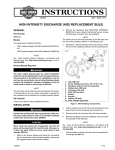
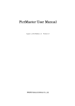
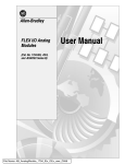
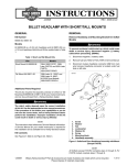
1
INSTRUCTIONS FOR INSTALLATION AND OPERATION
Type ABL Unfiltered SCR
Brushless DC Motor Control
Model 3910
Manual No. 074 00210A
IMPORTANT
Read this manual completely and carefully. Pay special
attention to all warnings, cautions, and safety rules. Failure to
follow the instructions could produce safety hazards which could
injure personnel or damage the control, motor, or other
equipment. If you have any doubts about how to connect the
control or motor, refer to the detailed sections of this manual.
QUICK REFERENCE
Figure 1 - Quick Reference Connection Diagram
2
TABLE OF CONTENTS
QUICK REFERENCE INSTALLATION ..................................................................2
GENERAL INFORMATION .................................................................................... 4
CONTROL DESCRIPTION AND FEATURES ........................................................5
SPECIFICATIONS .................................................................................................... 6
IMPORTANT SAFETY PRECAUTIONS ................................................................ 6
INSTALLATION INSTRUCTIONS ...................................................................... 10
Mounting the Control .......................................................................................... 10
Electrical Connections ......................................................................................... 10
Cable Assembly ............................................................................................. 11
Horsepower (DIP) Switch Settings ............................................................... 12
Commutation Sensor Connections ................................................................ 14
Motor Phase Connections .............................................................................. 14
Fuse Installation ............................................................................................. 14
Manual Control Input Connections ............................................................... 14
Electronic Control Input Connections ........................................................... 17
Tachometer Output ........................................................................................ 18
AC Power Connections ................................................................................. 19
OPERATING INSTRUCTIONS ............................................................................. 20
Preliminary Checks ............................................................................................. 20
Operating the Control .......................................................................................... 20
Internal Adjustments ........................................................................................... 21
TROUBLESHOOTING ........................................................................................... 23
WARRANTY ........................................................................................................... 26
FIGURES
Figure 1 - Quick Reference Connection Diagram ...................................................... 2
Figure 2 - Heatsink Orientation ............................................................................... 11
Figure 3 - Model 3983 Cable Assembly .................................................................. 12
Figure 4 - Control Circuit Board Detail ................................................................... 13
Figure 5 - Horsepower (DIP Switch) Settings and Fuse Selection Chart ............... 13
Figure 6 - Manual Speed Potentiometer/Interface Details ...................................... 15
Figure 7 - Manual Switch and Relay Control Inputs .............................................. 16
Figure 8 - Connection to Model 3984 Isolation Interface ........................................ 18
Figure 9 - Tachometer Output ................................................................................ 18
Figure 10 - Speed/Torque Curve Showing Reduced Torque at Low Speeds ......... 22
Mounting Template .................................................................................. Centerfold
© 1999 Bodine Electric Company. All Rights Reserved. Printed in U.S.A.
3
GENERAL INFORMATION
Congratulations!
And thank you for selecting a Bodine Type ABL-3900 Series Brushless DC
Motor Control. Your new control will provide the same excellent performance
and reliability that have been a Bodine tradition since 1905. Bodine Electric
Company takes pride in the quality of its products and in satisfying its customers. Every effort has been made to provide you with a product free of defects in
design, workmanship, and materials. In order for us to maintain our tradition of
quality, please report any cases of unsatisfactory service or products to Bodine
Electric Company promptly.
About This Manual
This manual contains the basic information needed to install and operate a
Bodine Model ABL-3910C Brushless DC Motor Control. It is organized in a
systematic, step-by-step fashion so that the system may be set up safely in the
shortest possible time. It does not profess to cover all details or variations in
equipment, nor to provide for every possible contingency associated with
installation, operation, or maintenance—and no warranty of fitness for purpose
is expressed or implied. Should further information be desired or should
particular problems arise which are not covered sufficiently for the user’s
purpose, the matter should be referred to the Bodine Electric Company.
The issuance of this manual does not confer to the recipient any license to
manufacture under any patents owned or controlled by the Bodine Electric
Company.
Safety Standards
Bodine products are designed and manufactured to comply to applicable safety
standards and in particular to those issued by ANSI (American National Standards Institute), NEMA (National Electrical Manufacturers Association), U.L.
(Underwriters Laboratories, Inc.), and CSA (Canadian Standards Association).
Type ABL controls “recognized by U.L., Inc.” are designated by having a "
"
symbol in the upper right corner of their nameplates. In addition, products that
are CSA certified, are identified by a "
" symbol. If you need specific
information regarding the third party approval status of Bodine products, contact
the nearest Bodine representative, or the home office.
4
CONTROL DESCRIPTION AND FEATURES
The ABL-3910C Brushless DC Motor Control is a chassis style control,
designed to be mounted into a separate control enclosure supplied by the user.
The control operates from a nominal 115 VAC, 50/60 Hz. power source. The
control provides electronic commutation and phase current switching needed to
operate brushless DC motors. DIP switch selectable current limit settings allow
the control to be used with a wide range of fractional horsepower motors and
gearmotors.
The ABL-3910C provides a 90 Volt unfiltered DC output. The control allows
motor speed to be manually or electronically controlled.
Motor direction of rotation, disabling, and soft starts and stops can be controlled
with manual switch inputs or by logic control. Since the control's signal
common is not at ground potential, interface circuitry is required to isolate logic
signals from the control. Trim potentiometers on the control board, allow
additional fine tuning of minimum and maximum speed settings, torque,
acceleration and deceleration time. A built-in "Smart Reverse TM circuit prevents
plug reversing by disabling the motor until it coasts to a stop before changing its
direction. A built-in shutdown circuit disables the control during overvoltage,
under-voltage, or invalid commutation sensor state conditions.
Specific Bodine motor sizes which can be used with these controls are listed in
the Chart in Figure 4.
Accessory Items
• Model 3983 Connection Cable Assembly - one end equipped with circular
connector; other end equipped with quick disconnects for phase leads and
connector for commutator leads. Length: 6ft. (See Figure 3)
• Model 3982 Extension Cable - extends cable between motor and control by
six feet. Both ends equipped with circular connectors for easy connection
between Model 3983 Cable and motor. Length: 6ft.
• Model 3984 Isolated Interface Module (See page 18.)
• Model 433 00270 Manual Speed Potentiometer Kit
5
SPECIFICATIONS
Input Voltage: .................................. 115 VAC ± 10%, 50/60 Hz (Single Phase)
Input Current: ................................. 6 Amps rms
Output Voltage: ............................... 0 to 90 VDC
Ambient Temperature: ................... 0 to 50o C (Maximum)
Control Hp Range: .......................... Up to 3/8 Hp
Control Speed Range: ..................... Up to 30:1
Control Speed Regulation: .............. Less than 1% of rated (Typical)
Line Voltage Compensation: .......... Negligible speed change with
changes in line voltage
Acceleration Time Range: .............. 0.2 to 10 seconds (0 to full speed)
Dimensions: ...................................... in: 5.5 W x 8.0 D x 1.8 H
cm: 14.0 W x 20.4 D x 4.6 H
Net Weight: ...................................... 2.0 lbs. (0.81 kg.)
IMPORTANT SAFETY PRECAUTIONS
The following safety precautions must be observed during all phases of installation, operation, service, and repair of this motor control product. Failure to
comply with these precautions or with specific warnings elsewhere in this
manual violates safety standards of design, manufacture and intended use of the
products. Bodine Electric Company assumes no liability for the customer’s
failure to comply with safety requirements and practices.
The use of electric motors and generators, like that of all utilization of concentrated power, is potentially hazardous. The degree of hazard can be greatly
reduced by proper design, selection, installation, and use but all hazards cannot
be completely eliminated. The reduction of hazards is a joint responsibility
between the user, the manufacturer of the driven or driving equipment and the
manufacturer of the control or motor.
6
The user should refer to Publication No. ANSI C5.1/NEMA MG 2. Safety
Standard for Construction and Guide for Selection, Installation and Use of
Electric Motors and Generators.” Available from:
National Electrical Manufacturers Association
2101 L Street N.W.
Washington, D.C. 20037, U.S.A.
☛
Warnings (such as the example below) highlight procedures which present
potential danger to people. Cautions highlight possible danger to equipment. Both are used throughout this manual. Warnings and Cautions must
always be followed.
WARNING
Dangerous voltages may be present in the electronic control and motor.
These voltages could cause serious injury or death. Use extreme
caution during handling, testing, and adjusting. Properly guard the
electronic control and motor to prevent accidental contact by all persons.
The chance of explosions, fires, or electric shocks can be reduced with
thermal and over-current protection, proper grounding, enclosure
selection, and good maintenance. The following safety considerations
are not intended to be all-inclusive. Specific references throughout this
manual should also be consulted.
CAUTION
These controls are designed to provide optimum performance when
used with Bodine electric Company motors. They should not be used
with other manufacturer's motors without first contacting the Bodine
Electric Company. Failure to contact Bodine in advance could cause
damage to the control or the motor.
Inspecting the Control
Check the items you received against your purchase order. Carefully examine
the control (and any optional kits or parts) for shipping damage. Parts errors
should be reported to Bodine. Shipping damage claims should be made to the
freight carrier.
7
Before installation, review the application to confirm that the proper motor and
control have been selected. This should be done after reading this manual and all
applicable safety standards. If in doubt, contact your Bodine representative, or
the home office if there is no representative in your area. Although Bodine
Electric Company assists its customers in selecting motors and controls for
specific applications, determination of fitness for purpose or use is solely the
customer’s responsibility.
Normal Operating Conditions
Unless otherwise agreed to by Bodine, all control nameplate ratings are based on
the following normal operating conditions. Consult Bodine Electric Company if
variations beyond these limits are anticipated.
1. Duty Cycle: 8 hours/day; 5 days/week, without frequent
reversals or starts and stops.
2. Maximum Ambient Temperature: 50o C (122o F) for chassis
controls; 40o C (104o F) for all encased controls.
3. Voltage: Within 10% of nameplate rating.
4. Frequency: Within 5% of nameplate rating.
5. Combined Variation of Voltage and Frequency: Within a
total of 10% providing frequency variation does not exceed 5%.
Grounding
Both electronic controls and motors must be securely mounted and adequately
grounded. Failure to ground properly may cause serious injury to personnel.
Fusing
Both the control input and output are fused. When fuses are replaced, they must
always conform to the values and ratings specified on the control’s nameplate or
in the fuse chart located in Figure 5.
Live Circuitry
Open-type electronics should be properly guarded or enclosed to prevent
accidental human contact with live circuitry. No work should be performed on
or close to the control or motor while the control is connected to the AC line. If
an AC line switch is used, it should be a Double Pole Single Throw (DPST), so
that both sides of the AC line are disconnected.
8
Environment
Open controls or controls in ventilated enclosures may emit flame during failure.
Bodine’s totally enclosed products are not explosion-proof, and Bodine does not
offer an explosion-proof motor, gearmotor, or control for hazardous locations
(e.g., in an environment of flammable or explosive gas, vapor, or dust). Bodine
recommends use of only approved explosion-proof products in hazardous
locations. Exceptions are allowed by the National Electric Code (NEC), but
NEC and NEMA safety standards should be studied thoroughly before
exercising this option.
Moisture increases the electrical shock hazard of electrical insulation. Therefore,
open-type or unsealed controls not specifically designed for such use, should be
protected from contact with liquids or moisture.
Ventilated Products
Open, ventilated products are suitable for clean, dry locations where cooling air
is not restricted. Do not insert anything into a product’s ventilation openings.
Servicing
Emergency field repairs must be made only by authorized Bodine service
representatives. Repairs made by persons not authorized by the Bodine Electric
Company will void the warranty. Field repairs must be limited to replacing an
entire printed circuit board assembly. Because of the danger of introducing
safety hazards, do not install substitute parts or perform any unauthorized
modifications to electronic PC boards, components or motors. To ensure
continued compliance with the design specifications and safety standards, the
electronic control or motor should be returned to Bodine Electric Company or an
Authorized Service Center for servicing.
WARNING
To avoid injury because of unsuspected mechanical motion, always
disconnect the 115 VAC power to the control before performing any
service procedures on the motor, control , or driven equipment.
9
INSTALLATION INSTRUCTIONS
WARNING
This control should only be installed by a qualified technician,
electrician or electrical maintenance person familiar with its
operation and associated hazards. The National Electrical Code
(NEC), local electrical and safety codes, and when applicable, the
Occupational Safety and Health Act (OSHA) should be observed
to reduce hazards to personnel and property.
The user must provide a proper enclosure for chassis type
controls. Circuitry is not at ground potential. Do not perform work
on or near the control while it is connected to the AC line.
CAUTION
Exposed circuit boards should be protected from electrostatic
discharge. The control board uses CMOS circuitry. Static
discharge into the control board must be avoided to prevent
component damage.
Mounting the Control
The mounting template (provided in the center of this manual) can be used to
position and mark the location of mounting holes on the surface where the
control is to be located. The control should be mounted vertically, using the
slots on either the narrow or wide surfaces of the heatsink. This arrangement
provides optimum air flow around the control. Refer to Figure 2.
Electrical connections
Read the following instructions as well as all of the applicable safety recommendations, before making any electrical connections between the control, motor, or
motion control electronics.
WARNING
The 115 VAC power line to the control should be the very last
connection made. Disconnect the power line before making any
other electrical connections.
10
Figure 2 - Heatsink orientation
Cable Assembly: The Model 3983 Cable Assembly, shown in Figure 3, is
designed to simplify the electrical connections to the ABL-3910C Control. One
end of the cable which connects to the motor is terminated with a circular type
connector. The other end which connects to the control has a six-pin rectangular
connector, three individual motor phase leads with quick disconnects, and an
earth ground lead.
11
Earth Ground Lead
Mates to Motor Connector
or Model 3982 Extension Cable
To Control
6
5
4
3
2
1
2
MOTOR
PHASE
LEADS
To Motor
Commutation Sensor Connector
Figure 3 - Model 3983 Cable Assembly
WARNING
The shield common is at a dangerous potential above ground and
presents a voltage hazard. Contact with the shield could cause
serious injury or death. If a non-Bodine cable is used or if a special
cable is fabricated, care should be taken to insulate all exposed
shield to avoid serious injury. The shield should only be connected to
the COM terminal on the Commutation Sensor Input Connector at the
control. No other shield connection should be made.
CAUTION
Only copper wire with a minimum 60° C rated insulation is
recommended if Bodine cable assemblies are not used. If your
control is equipped with a terminal block, it will accept leads up to
14 gauge. (18 gauge is the smallest recommended size.)
Horsepower (DIP Switch) Settings: Figure 4 shows a Horsepower Select
switch on the main control board which contains eight switch levers numbered
1 through 8. The chart in Figure 5 shows the proper DIP switch settings for
various Bodine motor types.
Determine the first four digits of the motor's type number from the nameplate.
Find the same four digits in the chart in Figure 5 to determine the proper settings
of the DIP switches. An insulated alignment tool should be used to adjust the
switch settings.
12
Figure 4 - Control Circuit Board Detail
Control
Model
Number
ABL-3910C
Motor or
Hp At full
Gearmotor Speed with
Type
Unfiltered
Control
22B2…
22B3…
22B4…
34B3…
34B4…
34B6…
1/32
1/22
1/14
1/11
1/9
1/6
Full
DIP Switch
Speed with
Levers
Unfiltered in the “On”
Control
Position
1725
2,6,7
1,2,6,7
1,3,6,7
1,2,3,6,7
2,4,6,7
1,5,6,7
Line
Fuse
(F1)
Motor
Fuse
(F2)
MDA 6/10
MDA 8/10
ABC-8 MDA 1-1/4
MDA 1-1/2
MDA 2
MDA 3
AC rms
Input
Current
0.7
0.9
1.3
1.7
2.2
3.1
Figure 5 - Horsepower (DIP Switch) Settings and Fuse Selection Chart
13
Commutation Sensor Connections: The commutation sensor leads are
prewired in the Model 3983 cable assembly and terminated in a six-pin connector (Figure 3). There is a corresponding "Commutation" connector on the main
control board (Figure 4). Mate the polarized cable connector to the "Commutation" connector on the control board. The connectors can only mate one way.
Motor Phase Connections: The ABL-3910C unfiltered control utilizes quick
connect terminals on the main control board. Refer to Figure 4.
Locate the Motor Phase Outputs labeled "A," "B," and "C" on the main
control board. Connect the phase leads as follows:
•
•
•
Brown to Motor Phase Output "A"
Red to Motor Phase Output "B"
Orange to Motor Phase Output "C"
Fuse Installation: The control input and output are fused. The line input fuse
has been installed at the factory. The control output or "Motor Fuse" must be
selected based on the size of the motor.
Line Fuse: The location of line fuse (F1) is shown in Figure 4. It should
always be replaced with a fuse of the same type and rating. Its rating can be
determined by referring to the chart in Figure 5.
Motor Fuse: The location of motor fuse (F2) is shown in Figure 4. The fuse
rating will vary with the size of the motor used. To determine the proper fuse
rating, locate the first four digits of your motor's type number on the motor
nameplate. Find the same four digits in the chart in Figure 5 to determine the
fuse size. The ABL-3910C is supplied without motor fuses.
Manual Control Input Connections: Motor speed, braking, direction of
rotation and deceleration can be controlled manually or electronically. Refer to
the following procedures for connecting control inputs.
14
CAUTION
The control board signal common is not at ground potential, any
external signal or equipment connected to the control must be
electrically isolated from ground (e.g., relay or optically isolated).
Non-isolated signals will damage the control and/or associated
external equipment.
Manual Speed Control: A Manual
Speed Potentiometer Kit for controlling motor speed is available from
Bodine (Model number 43300270).
The kit contains a 10K Ohm potentiometer, mounting hardware, and
three 24-inch long leads terminated
on one end with
1/4 inch quick connects. To connect
the speed potentiometer, proceed as
follows:
12V
10K
10K
Maximum
Speed
Adjustment
Minimum
Speed
Adjustment
10K
100K
Signal Common
51.1K
S3
10K
S2
100K
–
+
S1
Signal Common
1. Solder the three leads to the
potentiometer as shown in
Figure 1.
2. Mount the potentiometer in
the desired location.
3. Connect the speed pot to the
control board terminals as
follows:
• Blue to Terminal "S1"
• Orange to Terminal "S2"
• Yellow to Terminal "S3"
Figure 6 - Manual Speed
Potentiometer/Interface Details
Manual Disable, Direction of Rotation, and Deceleration: Mechanical switches
or relays can be used to switch the control inputs. Figure 7 shows a schematic
representation of manual or relay switched inputs.
15
NOTE: The DISCOM, DIRCOM, DECLCOM, S1, and COM terminals on the control board
are all connected in common.
12V
10K
4000 Series CMOS
DISABLE
DISCOM
Manual
Switches
or Relay
Contacts
12V
10K
4000 Series CMOS
DIR
DIRCOM
12V
10K
4000 Series CMOS
DECEL
DECLCOM
Signal
Common
Figure 7- Manual Switch and Relay Control Inputs.
The following chart lists the control functions relative to the state of the
mechanical switches or relays.
Switch
DISABLE1
DIR2
DECEL3
Closed
Stop
CW4
Decelerate
Open
Run
CCW4
Accelerate
1. The ABL-3910C does not include a braking module. When the DISABLE switch is closed, the
motor will simply coast to a stop.
2. The ABL-3910C includes a "Smart Reverse Circuit" which prevents plug reversing when the
DIRection switch is opened or closed. The motor will coast to a stop before changing direction.
3. The DECEL switch controls soft stops and starts. The degree of acceleration and deceleration
can be varied with the trim potentiometers on the control board. See Page 22.
4. The output shafts of gearmotors with odd number of stages (Bodine type designations ending
with W3, E1, or E3) will rotate in the opposite direction.
16
Electronic Control Input Connections: Optional Interface Boards are
available from Bodine and other manufacturers. They provide electrical
isolation between the input signal and the brushless DC motor control circuitry,
and are recommended for motion control applications requiring electronic
control of motor speed, rotational direction, deceleration, and disable.
Electronic Speed Control: Motor speed can be controlled with a 0 to +10 VDC
isolated signal with 0.1 mA current capability in lieu of the manual speed
potentiometer. This speed control input should be connected to terminal S2 on
the control board. The common side of the signal must also be isolated and
connected to terminal S1 on the main control board.
Logic Signal Control of Disable, Direction of Rotation, and Deceleration:
Motor disable, direction of rotation and deceleration can be controlled using
optically isolated logic signals from a programmable controller, personal
computer, or other electronics.
WARNING
Never rely on logic circuitry as a means of disabling the motor or
control. To prevent unsuspected mechanical motion and potential
injury, the 115 VAC power should always be disconnected
whenever logic circuits or the driven equipment are serviced .
Exercise extreme caution when using Programmable Logic Controllers (PLCs).
Although some may claim to have optically isolated output modules, their
output commons may be connected to other circuitry either within or connected
to the PLC. In such cases, the PLC outputs should be isolated from the
ABL-3900 Series control board, by a relay or by an electronic isolation module,
to prevent damage to the PLC or the ABL-3900 Series control.
If a Programmable Controller with a relay output module is not available, AC or
DC outputs from the PLC can be used to drive separate relay coils. See PLC
user's manual for application information. See Figure 6 to determine how to
connect relay contacts to the ABL-3910C.
17
Signal Isolation Using a Bodine Model 3984 Interface Module: Follow the
installation instructions provided with the module to isolate the input signals
between the control electronics and the ABL-3900 Series Control. See Figure 8
for connections.
Model 3984
ISO +
ISOICOM
VIN1
VIN2
IDIR
IDIS
ITAK
Analog IN
TAK
DIS
DIR
VOUT
COM
V+
TB2
T-OUT
DISABLE
DIR
S2
S1
Motor
ABL 3910
Brushless DC Motor Control
Figure 8 - Connection to Model 3984 Isolation Interface
Tachometer Output: When used with the Bodine ABL-3910 Brushless DC
Motor Controls, the Model 3984 module provides a digital tachometer output at
the ITAK terminal for monitoring motor speed. The output pulse levels are low
to high to low. The typical pulse width is 0.8 msec. for the ABL-3910. Twelve
pulses correspond to one motor revolution. The ITAK output provides an
unterminated open collector output. A pull-up resistor or another logic device is
required for measuring the output. See Figure 9 for assistance in interfacing the
ITAK output.
User Logic Supply
Unterminated
Open Collector
Output
UserSupplied
Pull-Up
Resistor
ITAK
Model 3984
Logic
Model 3984
V less than or
(+) equal to 55V
l less than or
equal to
2 mA
User Input
ICOM
Pull-Up Resistor Values for
Common Logic Supplies
+VDC
R (Ohms)
+5V
4.7K
+12V
10K
+12V
15K
User Equipment
Figure 9 - Tachometer output
18
AC Power Connections: Power should always be the last connection made
during installation and the first item to be disconnected before servicing.
WARNING
The control and motor must be securely and adequately
connected to earth ground as indicated below. Failure to ground
properly may result in serious injury.
Power Input: The ABL-3910C unfiltered control utilizes quick connect terminals. Refer to Figure 4.
Locate the quick connect terminalslabeled "L" and "N" on the main control
board near the line fuse. Connect AC power as follows:
1. Hot side of 115 VAC line to Terminal "L".
2. Neutral side of 115 VAC line to Terminal "N".
3. A green screw and cup washer are provided on the short surface of the
heat sink for chassis ground connections.
19
OPERATING INSTRUCTIONS
WARNING
Explosions, fires, or electric shock hazards can be reduced through thermal
and over-current protection, good maintenance, proper grounding, and
enclosure selection. Review safety considerations outlined in "Safety
Precautions” and "Installing the Control.”
Preliminary Checks
1. Before starting the control, check all fuses, connections, and adjustments such
as horsepower DIP switch settings.
2. Proper consideration should be given to all rotating members. Before starting,
be sure keys, pulleys, etc. are securely fastened. Proper guards should be
provided to prevent hazards to personnel while the equipment is rotating.
3. Mechanical considerations such as proper mounting and alignment of
products, and safe loads on shafts and gears should be reviewed. Do not
depend upon gear friction to hold loads.
4. The motor or gearmotor should be securely mounted (because of possible
reaction torque). Test the motor/gearmotor unloaded to be certain that proper
connections have been made.
Operating the Control
WARNING
The 115 VAC line to the driver should be switched off before starting.
1. Turn input power OFF and set the speed potentiometer to ZERO (fully
counterclockwise). If a Disable switch is used, close the switch. If a Direction switch is used set it for the desired direction of rotation. If a Deceleration switch is used, open the switch. See Chart in Installation Instructions,
Manual Control Input Connections.
2. Connect the 115 VAC power line to the external power source. Then turn on
the 115 VAC input power to the control.
3. Open the Disable switch, if used.
4. Turn speed potentiometer knob until motor rotates. Then adjust the potentiometer to achieve the desired speed. If you wish to reduce the torque level,
refer to Internal Adjustments below.
5. If the motor does not operate, first observe if the green POWER light and red
20
FAULT light are on (refer to Figure 4 for location). Then disconnect the AC
power to the control and check all connections and fuses. If a fuse is blown
and the motor is not locked (stalled) or overloaded, do not replace the fuse.
The control may be damaged. Refer to Troubleshooting and follow instructions. If the motor is overloaded, reduce the load and replace blown fuses
with those of the proper type and rating as specified in Figure 5.
Internal Adjustments
Your control has been factory-adjusted for the following settings:
Minimum speed: 0 RPM
Maximum speed: 1725 RPM
Acceleration: 2 seconds
Deceleration: 2 seconds
Torque: 200% of rated (based on proper DIP switch settings)
Refer to Figure 4 for the trim potentiometer locations and approximate initial
settings. If you need to readjust the control for your specific applications,
proceed as follows:
WARNING
Use a non-metallic or insulated adjustment tool (such as a television alignment
tool) for internal adjustments. Circuit components are not at ground potential
and accidental short circuiting and shock hazard may occur with conducting
tools. Adjustment should be made only by qualified service personnel.
Minimum and Maximum Speed: The MIN and MAX trim potentiometers
have been factory calibrated. The lowest MIN trim potentiometer setting (fully
counterclockwise) corresponds to 0 RPM and the highest MIN setting (fully
clockwise) corresponds to approximately 30% of rated speed.
The lowest MAX trim potentiometer setting (fully counterclockwise) corresponds to 60% of rated speed and the highest MAX trim potentiometer setting
(fully clockwise) corresponds to approximately 120% of rated speed.
Refer to Figure 4 for trim potentiometer location and settings. Adjustment of
the MIN and MAX trim potentiometers may have to be repeated several times to
arrive at the desired speeds.
NOTE: Increasing the MIN potentiometer setting will increase the maximum speed beyond
nameplate speed. The MAX trim potentiometer will need to be readjusted.
21
Torque (Current) Limiting Adjustment: The TORQ trim potentiometer
(Figure 4) has been calibrated so that the motor will never see more than 200 to
250% of its rated current input if the DIP switches are set properly. The motor’s
torque output can be reduced to zero or stall torque. Turn the TORQ trim
potentiometer counterclockwise to decrease the torque and clockwise to increase
the torque.
NOTE: For a given setting of the TORQ potentiometer, the output torque at speeds below 100
RPM will be less than at higher speeds. Refer to Figure 8.
Figure 10 - Speed/Torque Curve showing decreased torque at lower speeds
Acceleration Adjustment: Adjusting the ACCEL trim potentiometer (See
Figure 4) counterclockwise decreases the motor's acceleration time down to a
minimum of approximately 0.2 seconds. A clockwise adjustment increases the
rate up to a maximum of approximately 10 seconds.
Deceleration Adjustment: Adjusting the DECEL trim potentiometer (See
Figure 4) counterclockwise decreases the motor’s deceleration time down to a
minimum of approximately 0.2 seconds. A clockwise adjustment increases the
rate up to a maximum of approximately 10 seconds.
22
TROUBLESHOOTING
WARNING
Disconnect the control from the power source before working on
the control, motor, or driven equipment.
Your control should not require maintenance under normal conditions. If you
encounter a problem, read all applicable instruction literature provided with this
control and accessories, and double-check the wiring. The charts on the
following pages also provide assistance in troubleshooting those problems
which usually occur during normal installation and operation.
If the problem persists, contact your source of purchase or a Bodine Authorized
Service Center and describe the problem in detail. Include all the nameplate
data. Do not disassemble the product unless authorized by Bodine Electric
Company. Performing repairs not authorized by Bodine Electric Company or
removing screws will void the Warranty.
SYMPTOM
PROBABLE CAUSE
CORRECTIVE ACTION
CONTROL BLOWS
LINE FUSE
Control or motor
connected to or shorted
to earth ground
Check for shorts and repair
control and/or motor as required.
Shorted phase leads
wiring incorrect
Correct wiring.
Damaged control
Components
Contact Bodine or Service
Center for assistance.
MOTOR WILL
NOT START AND
POWER LIGHT
IS OFF
Open line fuse
Replace fuse. Refer to Figure 5
for proper value.
Open line switch
Close the line switch.
MOTOR WILL
NOT START AND
POWER LIGHT
IS ON
Motor overloaded
Correct load or choose larger
motor.
TORQ trim pot is out
of adjustment
Visually check setting (Figure 4).
Adjust TORQ trim pot, page 21.
23
SYMPTOM
PROBABLE CAUSE
CORRECTIVE ACTION
MOTOR WILL
NOT START AND
POWER LIGHT
IS ON (Cont.)
Open motor fuse
Replace fuse. Refer to Figure 5
for proper values
Speed potentiometer
set to zero
Increase speed potentiometer
setting.
Closed DISABLE switch
Open DISABLE switch and
restart.
Closed DECEL switch
Open the DECEL switch.
Electrical noise on
DISABLE and/or
DECEL input
Use shielded cable.
Damaged motor
Repair or replace motor.
Mistake in motor
commutation sensor
connections
Correct wiring.
Electric noise
on commutation sensor
inputs
Use shielded cable.
Damaged motor
Repair or replace motor.
MAX trim pot set
too low
Adjust trim pot, page 20.
Speed potentiometer
set to low
Increase speed potentiometer
setting.
Motor overloaded
Reexamine the load parameters.
TORQ trim pot is out
of adjustment
Visually check setting (Figure 4).
Adjust TORQ trim pot, page 21.
Wrong horsepower
setting
Check DIP switch setting, page 13.
Damaged component
on the control board
Contact Bodine or Service Center
for assistance.
MOTOR WILL NOT
START AND FAULT
LIGHT IS ON
MOTOR WILL NOT
COME UP TO
SPEED
24
SYMPTOM
PROBABLE CAUSE
CORRECTIVE ACTION
MOTOR SPEED IS
UNSTABLE OR
PULSATES
Wrong horsepower
setting
Check DIP switch setting, page 13.
Motor and load not
correctly aligned
Perform alignment.
Damaged motor
Repair or replace motor.
Speed potentiometer
set too low
Increase speed potentiometer
setting.
Wrong horsepower
setting
Check DIP switch setting, page 13.
MOTOR WILL NOT
MAINTAIN SPEED
UNDER LOAD
MOTOR WILL NOT
TORQ trim pot is out
MAINTAIN SPEED
of adjustment
UNDER LOAD (Cont.)
Motor overloaded
Visually check setting (Figure 4).
Adjust TORQ trim pot, page 21.
MOTOR WILL NOT
STOP WITH SPEED
POT ADJUSTED
AT ZERO
MIN trim potentiometer
is set too high
Turn the MIN trim pot
CW until motor stops.
Open connection on
speed potentiometer
Check S1, S2, S3 connections.
Defective speed
potentiometer
Replace the potentiometer.
Reexamine the load parameters.
Note: The Disable input should be used when the motor is expected to remain stopped.
NO SPEED
ADJUSTMENT
Defective speed
potentiometer
Replace the potentiometer.
Open connection on
speed potentiometer
Check S1, S2, S3 connections.
25
BODINE LIMITED WARRANTY
The Bodine Electric Company warrants all products it manufactures to be free of
defects in workmanship and materials when used under Normal Operating
Conditions and when applied in accordance with nameplate specifications. This
warranty shall be in effect for a period of twelve months from date of purchase
or eighteen months from date of manufacture, whichever comes first.
The Bodine Electric Company will repair or replace at its option, any of its
products which has been found to be defective and is within the warranty period,
provided that the product is shipped freight prepaid, with previous authorization,
to Bodine’s plant in Chicago, Illinois 60618 U.S.A., or to the nearest Bodine
Authorized Service Center. At its option, all return shipments are F.O.B.
Bodine’s plant or Authorized Service Center. Bodine is not responsible for
removal, installation, or any other incidental expenses incurred in shipping the
products to or from Bodine.
This warranty is in lieu of any other expressed or implied warranty—including
(but not limited to) any implied warranties of merchantability and/or fitness for
a particular use or purpose.
Bodine’s liability under this warranty shall be solely limited to repair or replacement of the Bodine product within the warranty period and Bodine shall not be
liable, under any circumstances, for any consequential, incidental or indirect
damages or expenses associated with the warranted products.
Commutator and/or brush wear and its associated effects are a normal occurrence and are not covered by this warranty unless otherwise agreed to by Bodine
in writing.
Any Bodine product which is damaged due to misuse, abuse, negligence or has
been modified or dismantled without the knowledge or written consent of
Bodine, is not covered by this warranty.
Control Type _____________________ Serial No. ____________________
Date of Purchase _____________ Place of Purchase ____________________
26
NOTES
27
Bodine Electric Company
2500 W. Bradley Place
Chicago, Illinois 60618 U.S.A.
TEL: (312) 478-3515
FAX: (312) 478-3232
bodine-electric.com
Printed in U.S.A.
R
Manual No. 074 00210A (AP)