1
User manual | ERC 21X temperature controllers series
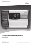
ERC 21X, smart multipurpose
refrigeration controller
4
push buttons, a
big display and
an intuitive menu
structure ensure
superior ease of use.
www.danfoss.com/erc
Table of contents
1|Introduction
1.1|Application
1.2| General Description
1.3| ERC 21X Series
1.3.1| ERC 211
1.3.2| ERC 213
1.3.3| ERC 214
2
4
4
4
5
5
5
5
2|
2.1|
2.2|
2.3|
2.4|
2.5|
2.6|
Key features
Voltage protection
Compressor protection
Compressor protection against high condensing temperature
Pre-defined applications
Fan pulsating during compressor OFF cycle
Defrost on Demand
6
6
6
6
7
9
10
3|
Technical Specification
10
4|Installations
4.1| Dimensions (mm)
4.2|Mounting
4.3| Installation steps
4.4| Electrical connection diagram
4.4.1| ERC 211 - connection diagram
4.4.2| ERC 213 - connection diagram
4.4.3| ERC 214 - connection diagram
4.5| Power supply
4.6|Sensors
4.7| Electric noise
11
11
11
11
12
12
12
12
13
13
13
5|
5.1|
5.2|
5.3|
5.4|
5.5|
5.6|
5.7|
5.8|
5.9|
Menu Navigation and overview
Key functions and display Icons
Quick Configuration at power up
Menu Structure
Quick Configuration via “cFg” menu
Adjust set point temperature
Initiate a manual defrost
Initiate a pull down
View active alarm
Unlock keyboard
13
13
13
14
15
15
15
15
15
15
6|
Menu functions
16
7|
Parameter table
7.1| Parameter table - ERC 211
7.2| Parameter table - ERC 213
7.3| Parameter table - ERC 214
7.4| Alarm Code
7.5|Troubleshooting
22
22
25
29
33
33
8|Ordering
8.1|Sensors
33
34
FR · ERC 21X user manual · DKRCC.ES.RL0.H4.02/520H9845 · ©Danfoss
FR · ERC 21X user manual · DKRCC.ES.RL0.H4.02/520H9845 · ©Danfoss
3
1|Introduction
1.1|Application
ERC 21X is a smart multipurpose refrigeration controller
designed to fulfill today’s requirement of commercial
refrigeration applications. This controller is suitable for high,
medium and low temperature applications with natural,
electrical and hot gas defrost compatibilities.
Typical applications include Glass door merchandisers,
commercial fridges and freezers, cold rooms and various
other commercial refrigeration applications.
1.2|
General Description
ERC21X controller comes with four push buttons, a big
display, easy and intuitive menu structure and pre-defined
applications ensure ease of use. Controller is loaded
with energy efficiency features like smart evaporator fan
management, day/night mode and defrosts on demand
features.
High Effect 16 A relay enable direct connection of heavy
loads without use of intermediate relay: up to 2 hp
compressors depending on its power factor and motor
efficiency (greater than 0.65 for 230 V and greater than
0.85 for 115 V).
Safe operation of the unit is ensured through voltage
protection and high condensation temperature protection
features.
4
FR · ERC 21X user manual · DKRCC.ES.RL0.H4.02/520H9845 · ©Danfoss
1.3|
ERC 21X Series
Three version of ERC 21X is available in both 230 V / 50/60 Hz and 115 V / 60 Hz.
–– ERC 211: single relay output for refrigeration and heating applications.
–– ERC 213: three relays outputs for ventilated refrigeration applications.
–– ERC 214: four relays outputs for ventilated refrigeration applications.
1.3.1| ERC 211
ERC 211 has one relay output and two inputs
(1 analogue, 1 analogue/digital).
This controller can be used for either cooling or heating
applications.
Outputs:
–– Relay 1: compressor/solenoid valve control or simple
heater in case of heating application Inputs.
Inputs:
–– Input1: cabinet/control sensor (Sair).
–– Input 2: condenser sensor or digital inputs which can
be configured for various functions as mentioned under
menu code o02.
Sair
DO1
Sc
DI1
DI2
1.3.2| ERC 213
ERC 213 has three relays outputs and four inputs
(2 analogues, 1 analogue/digital, 1 digital) for cooling
applications.
Outputs:
–– Relay 1: compressor/solenoid valve control.
–– Relay 2: can be configured either defrost or external alarm.
–– Relay 3: fan control.
Inputs:
–– Input 1: cabinet/control sensor (Sair).
–– Input 2: defrost sensor (S5).
–– Input 3 : condenser sensor (Sc) or digital input which can
be configured to various functions as mentioned under
menu code “o02”.
–– Input 4: digital input which can be configured to various
functions as mentioned under menu code “o37”
Sair
S5
DO2
DO3
DI1
DI2
1.3.3| ERC 214
ERC 214 has four relays outputs and four inputs (2 analogue,
1 analogue/digital, 1 digital) for cooling applications.
Outputs:
–– Relay 1: compressor/solenoid valve control.
–– Relay 2: defrost control.
–– Relay 3: fan control.
–– Relay 4 : this can be configured for either light or external
alarm.
Inputs:
–– Input 1: cabinet/control sensor (Sair).
–– Input 2: defrost sensor (S5).
–– Input 3 : condenser sensor (Sc) or digital input which can
be configured to various functions as metioned under
menu code “o02”.
–– Input4: digital input which can be configured for various
functions as mentioned under menu code “o37”.
DO1
Sc
DO4
Sair
S5
DO2
DO1
Sc
DO3
FR · ERC 21X user manual · DKRCC.ES.RL0.H4.02/520H9845 · ©Danfoss
5
2|
Key features
2.1|
Voltage protection
High voltage limit
Protection against high and low voltage by limiting the
compressor operation within specified voltage limits.
Whenever the supply voltage goes beyond the defined
voltage protection limits controller will shut the compressor
OFF and flashes alarm on the display.
It will restore the operation when the voltage falls under the
operating range respecting minimum stop time.
Low voltage cut-out
limit (alarm and
compressor stop)
Compressor protection
Parameters for Minimum ON and OFF time, protect the
compressor by short cycling/sudden switching ON and OFF
by defining minimum ON and OFF time.
Power to compressor
2.2|
Low voltage cut-in
limit (compressor start)
min run time
ON
OFF
min stop time
Temperature
time
CUT-IN
CUT-OFF
time
2.3|
Compressor protection against
high condensing temperature
If the condenser is blocking up with dirt and thereby reaches
a too high condensing temperature, controller will give
the user early warning through condenser alarm and if
temperature rises further it will switch the compressor OFF.
If the temperature measured by the condenser sensor (Sc)
is reaching the set ”pre alarm limit” a alarm is raised, but no
further action is taken.
This is used to indicate to the user that something is wrong
with the condenser. Often the reason is that that the air flow
to the condenser is restricted (dirt) or because the condenser
fan is broken.
The alarm will reset if the condenser temperature drops back
by 5 °C. If the measured condenser temperature continues
to increase and reaches the set “Block limit” the compressor is
stopped and it is restricted from starting again until the alarm
is reset manually.
6
FR · ERC 21X user manual · DKRCC.ES.RL0.H4.02/520H9845 · ©Danfoss
Sc temperature °C
Block limit
Pre alarm limit
Pre alarm OK
Sc temperature °C
Compressor
Pre alarm
Block alarm
T1 T2
T3 T4
2.4|
Pre-defined applications
The purpose of the Predefined applications is to give the user an easy and fast way to configure the controller to a specific
application based on storage temperature (LT, MT, HT), defrost type (none, natural, electrical) and
defrost method (terminated on time or temperature).
When user select specific application based on their requirements, the controller will load a specific set of parameter values
and will hide parameters that are not relevant for the selected application.
Adjustment of the set of parameters value will be still possible at any time.
In addition to pre-defined applications, all controller versions have two standard applications, one with full list of parameters
and another with simplified list of parameters, that allows the user to make their own customized parameter settings
(AP0 and AP5 in case of ERC211 and AP0 and AP6 in case of ERC213 / ERC214).
Pre-defined application table of ERC 211 controller
App
Mode
Description
App 0
Cooling/ No predefined application
Heating
App 1
Cooling Medium temperature without defrost
App 2
Cooling Medium temperature with timed natural defrost
App 3
Cooling Medium temperature with natural defrost stop on
air temperature
App 4
Heating Heating Thermostat
App 5
Cooling/ No predefined application with simplified list of
Heating parameter
Temperature
Defrost type
Defrost end
(4 – 20 °C)
(2 – 6 °C)
(2 – 6 °C)
None
Natural
Natural
(20 – 60 °C)
None
None
Time
Air
temperature
None
Selection 1 covers applications where a standard cooling thermostat is needed and no defrosts are performed.
Selection 2 covers normal temperature applications with natural defrost with stop on time.
Selection 3 covers normal temperature applications with natural defrost with stop on air temperature.
Selection 4 covers applications where a simple heating thermostat is needed (no defrost).
Selection 5 covers applications where a reduced parameter list is recommended.
ERC 211 - APP 4
ERC 211 - APP 1/2/3
DI1
230 V AC
Sair
DI1
Sair
230 V AC
DO1
DO1
FR · ERC 21X user manual · DKRCC.ES.RL0.H4.02/520H9845 · ©Danfoss
7
Pre-defined application table of ERC 213 controller
App
Mode
Description
App 0
Cooling No predefined application
Medium temperature ventilated refrigeration units
App 1
Cooling
with timed natural defrost
Medium temperature ventilated refrigeration units
App 2
Cooling
with timed electrical defrost
Low temperature ventilated refrigeration units with
App 3
Cooling
timed electrical defrost
Medium temperature ventilated refrigeration units
App 4
Cooling
with electrical defrost (by temperature)
Low temperature ventilated refrigeration units with
App 5
Cooling
electrical defrost (by temperature)
No predefined application with simplified list of
App 6
Cooling
parameters
Temperature
Defrost type
Defrost end
(2 – 6 °C)
Natural
Time
(0 – 4 °C)
Electrical
Time
(-26 – -20 °C)
Electrical
Time
(0 – 4 °C)
Electrical
Temperature
(-26 – -20 °C)
Electrical
Temperature
Selection 1 covers normal temperature applications with natural defrost with stop on time.
Selection 2 and 3 covers respectively medium and low temperature applications with electrical defrost with stop on time.
Selection 4 and 5 covers respectively medium and low temperature applications with electrical defrost with stop on
defrost sensor “S5”.
Selection 6 covers applications where a reduced parameter list is recommended.
ERC 213 - APP 1
DI1
DI2
ERC 213 - APP 2-3
Sair
230 V AC
DI2
Sair
230 V AC
DO1
8
DI1
DO2 DO3
ERC 213 - APP 4-5
DI1
DI2
S5
230 V AC
DO1
DO2
FR · ERC 21X user manual · DKRCC.ES.RL0.H4.02/520H9845 · ©Danfoss
DO3
DO1
DO2
DO3
Sair
Predefined application table for ERC 214
App
Mode
Description
App 0
Cooling No predefined application
Medium temperature ventilated refrigeration units
App 1
Cooling
with timed natural defrost
Medium temperature ventilated refrigeration units
App 2
Cooling
with timed electrical defrost
Low temperature ventilated refrigeration units with
App 3
Cooling
timed electrical defrost
Medium temperature ventilated refrigeration units
App 4
Cooling
with electrical defrost (by temperature)
Low temperature ventilated refrigeration units with
App 5
Cooling
electrical defrost (by temperature)
No predefined application with simplified list of
App 6
Cooling
parameters
Temperature
Defrost type
Defrost end
(2 – 6 °C)
Natural
Time
(0 – 4 °C)
Electrical
Time
(-26 – -20 °C)
Electrical
Time
(0 – 4 °C)
Electrical
Temperature
(-26 – -20 °C)
Electrical
Temperature
Selection 1 covers normal temperature applications with natural defrost with stop on time.
Selection 2 and 3 covers respectively medium and low temperature applications with electrical defrost with stop on time.
Selection 4 and 5 covers respectively medium and low temperature applications with electrical defrost with stop on
defrost sensor “S5”.
Selection 6 covers applications where a reduced parameter list is recommended.
ERC 214 - APP 1
DI1
DI2
ERC 214 - APP 2-3
Sair
230 V AC
DI2
Sair
230 V AC
DO1
2.5|
DI1
ERC 214 - APP 4-5
DO3
DO4
DI1
DI2
S5
Sair
DO3
DO4
230 V AC
DO1
DO2
DO3
DO4
DO1
DO2
Fan pulsating during compressor
OFF cycle
This is an energy saving feature. During compressor OFF cycle controller will run the fan with defined duty cycle to maintain
uniform temperature and delay the need of compressor switching ON
FR · ERC 21X user manual · DKRCC.ES.RL0.H4.02/520H9845 · ©Danfoss
9
2.6|
Defrost on Demand
This feature records and averages the evaporator temperature recorded during the first three cut out of compressor
immediately after defrost. The controller will constantly follow the evaporator temperature and compare with the above
recorded average temperature. In between two defrosts, If the evaporator temperature goes below the previously recorded
average temperature by “defrost on demand” value “d30”, defrost will be triggered.
–– This function can only be used in 1:1 systems.
–– This function is disabled when the parameter “defrost on demand” is set to 20.
–– Defrost on demand is triggered only if the time since the last defrost session has ended is greater than ¼ of the defrost
interval or 2 hours whichever is lesser.
–– Defrost doesn’t start by this method during the following scenarios.
–– Pull down mode.
–– Night mode.
–– Main switch in DI or main switch in Menu is in OFF position.
–– Manual control mode.
–– Evaporator sensor senses a temperature which is greater than 0 °C.
3|
Technical Specification
FEATURES
Power supply
Rated power
DESCRIPTION
115 V AC / 230 V AC 50/60 Hz, galvanic isolated low voltage regulated power supply
Less than 0.7 W
4 inputs:
Inputs
2 analogue, 1 analogue/digital and 1 digital
NTC 5000 Ohm at 25 °C, (Beta value=3980 at 25/100 °C - e.g. EKS 211)
NTC 10000 Ohm at 25 °C, (Beta value=3435 at 25/85 °C - e.g. EKS 221)
Allowed sensor types
PTC 990 Ohm at 25 °C, (e.g. EKS 111)
Pt1000, (e.g. AKS 11, AKS 12, AKS 21)
Sensors included in Kit Solution NTC 10000 Ohm at 25 °C, cable length: 1.5 m
Measuring range:
-40 – 105 °C (-40 – 221 °F)
Accuracy
Controller accuracy:
±1 K below -35 °C, ±0.5 K between -35 – 25 °C,
±1 K above 25 °C
DO1 Compressor relay:
16 A, 16 (16) A, EN 60730
10 FLA / 60 LRA at 230 V, UL60730
16 FLA / 72 LRA at 115 V, UL60730
DO2 Defrost relay:
8 A, 2 FLA / 12 LRA, UL60730
Output
8 A, 2 (2 A), EN60730
DO3 Fan relay:
3 A, 2 FLA / 12 LRA, UL60730
3 A, 2 (2 A), EN60730
DO4 Alarm/Light relay:
2A
Display
LED display, 3 digits, decimal point and multi-function icons, °C + °F scale
Operating conditions
-10 – 55 °C (14 – 131 °F), 90% Rh
Storage conditions
-40 – 70 °C (-40 – 158 °F), 90% Rh
Front : IP65 (Gasket integrated)
Protection
Rear: IP00
Environmental
Pollution degree II, non-condensing
Resistance to heat and fire
Category D (UL94-V0)
EMC category
Category I
UL recognition (US & Canada) (UL 60730)
ENEC (EN 60730)
CQC
CE (LVD & EMC Directive)
Approvals
EAC (GHOST)
NSF
ROHS2.0
HACCP temperature monitoring in compliance with EN134785 Class I,
when used with AKS 12 sensor
10
FR · ERC 21X user manual · DKRCC.ES.RL0.H4.02/520H9845 · ©Danfoss
4|Installations
4.1|
Dimensions (mm)
36
28
71
83
61.2
66
Rear mounting (lock with clips)
29
Drilling template
4.2|Mounting
Mounting
4.3|
––
––
––
––
Dismounting
Installation steps
Place the wired controller in the slot and ensure rubber sealing is resting properly on the mounting surface.
Slide the mounting clips along the rails of the rear plastic from the rear side of the panel.
Slide the clips towards mounting surface until controller is firmly fixed.
To remove the controller, one needs to skillfully unlatch the snapping tab and pull the clips backwards.
FR · ERC 21X user manual · DKRCC.ES.RL0.H4.02/520H9845 · ©Danfoss
11
4.4|
Electrical connection diagram
4.4.1| ERC 211 - connection diagram
Programming key – EKA 183A
GND
TX
RX
+5V
DO1
15
16
17
GND
1
2
3L
4N
~
~
~
~
5
6
7
8
9
10
Sair
Power supply
(according to the product code number)
18
GND
11
12
13
14
DI/Sc
4.4.2| ERC 213 - connection diagram
Programming key – EKA 183A
GND
TX
RX
+5V
DO2 DO3
DO1
15
16
17
GND
1
2
3L
4N
~
~
~
~
5
6
7
8
9
10
Sair
Power supply
(according to the product code number)
18
GND
11
12
S5
Sc/DI1
13
14
DI2
4.4.3| ERC 214 - connection diagram
Programming key – EKA 183A
GND
TX
RX
+5V
DO2 DO3 DO4
DO1
15
16
17
GND
12
1
2
3L
4N
~
~
~
~
5
6
7
Power supply
(according to the product code number)
FR · ERC 21X user manual · DKRCC.ES.RL0.H4.02/520H9845 · ©Danfoss
8
9
Sair
10
18
GND
11
12
S5
Sc/DI1
13
14
DI2
4.5|
Power supply
115 V AC / 230 V AC / 50/60 Hz (Refer to the controller label).
4.6|Sensors
––
––
––
––
––
Sair
S5
Sc
Di1
Di2
4.7|
Control sensor.
Defrost (evaporator) sensor.
Condenser sensor.
Digital input - configurable to the functions listed under menu code o02.
Digital input - configurable to the functions listed under menu code o37.
Electric noise
Cables for sensors and DI inputs must be kept separate from other electric cables:
–– Use separate cable trays.
–– Keep a distance between cables of at least 10 cm.
–– Long cables at the DI input should be avoided.
5|
Menu Navigation and overview
5.1|
Key functions and display Icons
Key Function
Press and hold at power up:
FACTORY RESET (“FAC” is displayed)
Press for one second: BACK
Press and hold: PULL-DOWN
Display Icons
5.2|
Press for one second: UP
Press and hold: ON/OFF
Press for one second: DOWN
Press and hold: DEFROST
Press for one second: TEMPERATURE SETPOINT/OK
Press and hold: MENU
Night mode (Energy saving)
Fan running
Compressor running (Flashes in pull-down mode)
Active alarm
Defrost
Unit (°C or °F)
Quick Configuration at power up
–– STEP 1: power on
–– STEP 2: select the quick configuration menu
Within 30 seconds of power on, press “<” BACK for 3 seconds. The main switch “r12” is automatically set to OFF.
–– STEP 3: select pre-installed application “o61”
The display automatically shows the application selection parameter “o61”.
Press SET to select the pre-installed application.
The display shows the default value (eg. “AP0” flashing).
Choose the application type by pressing UP/DOWN and press SET to confirm.
The controller presets parameter values according to the selected application and does not hide relevant parameters.
Tip: you can easily move from AP0 to AP6, and thus select the simplified list of parameters, by pressing the UP key (circular list).
App
Description (e.g. for ERC213 and ERC214)
App 0 None (no preset application)
App 1 Medium temperature (2 – 6 °C), ventilated ref. units with timed natural defrost
App 2 Medium temperature (0 – 4 °C), ventilated ref. units with timed electrical defrost
App 3 Low temperature (-26 – -20 °C), ventilated ref. units with timed electrical defrost
App 4 Medium temperature (0 – 4 °C), ventilated ref. units with electrical defrost (by temperature)
App 5 Low temperature (-26 – -20 °C), ventilated ref. units with electrical defrost (by temperature)
App 6 None (no preset application) with simplified parameter list
Note: refer to chapter 2.4 - “Pre-defined Applications” for a complete description of the available applications.
FR · ERC 21X user manual · DKRCC.ES.RL0.H4.02/520H9845 · ©Danfoss
13
–– STEP 4: select sensor type “o06”
The display automatically shows sensor selection parameter “o06”.
Press SET to select the sensor type.
The display shows the default value (eg. “n10” flashing).
Choose sensor type by pressing UP/DOWN (n5=NTC 5 K, n10=NTC 10 K, Ptc=PTC, Pt1=Pt1000) and press SET to confirm.
NOTE: all sensors must be the same type.
–– STEP 5: configure DO4 output “o36”
The display automatically shows the “o36” parameter to configure “DO4” output. (Available only in 4 relays model).
Select light “Lig” or alarm “ALA” as per the application and press SET to confirm.
The display returns to normal display mode and the control is started.
5.3|
Menu Structure
SET: press for 3 seconds to access
status, setup and service
1) Parameter groups
Password (if enabled)
3) Value
Status input
2) Parameter name
SET
Configuration
Application
1-2-3-4-5-6
Main switch
SET
Application
Application 0
Sensor type
Application
1-2-3-4-5-6
Scroll through the
parameter names
DO4 configuration
(only for 4 relays model)
Scroll through the
parameter groups
14
FR · ERC 21X user manual · DKRCC.ES.RL0.H4.02/520H9845 · ©Danfoss
5.4|
Quick Configuration via “cFg” menu
––
––
––
––
––
Press SET for three seconds to access the parameters groups.
Select “CFg” menu and press SET to enter. The first menu “r12” (main switch) is displayed.
Switch OFF main switch (r12=0) for changing the pre-installed application.
Press UP/DOWN to scroll through the parameter list.
Configure the “o61” parameter to select a pre-installed application:
–– Press SET to access the “o61” parameter.
–– Press UP/DOWN to select an application.
–– Press SET to confirm, “o61” is displayed.
–– Continue to set the next parameters (“o06” sensor type and “o36” DO4 configuration) in the “cFg” menu.
5.5|
Adjust set point temperature
(short press) SET: adjust setpoint temperature.
UP/DOWN: change the temperature setpoint (in setting mode the setpoint flashes).
SET: save the temperature setpoint.
5.6|
Initiate a manual defrost
DEFROST: press for 3 seconds to initiate a defsost.
DEFROST: press for 3 seconds to stop manual defrost.
The DEFROST icon is shown during defrost.
5.7|
Initiate a pull down
PULL DOWN: press for 3 seconds to initiate pull down.
“Pud”: is shown for 3 seconds to indicate pull down.
The PULL DOWN icon flashes during pull down.
PULL DOWN: press for 3 seconds to stop pull down.
5.8|
View active alarm
Temperature and alarm codes
alternate flashes until the alarm
is resolved. The alarm bell is shown.
5.9|
Unlock keyboard
- After 5 minutes of no activity, the keypad is locked (if P76=yes).
- When the keypad is locked any button press shows “LoC” in the display.
- Press UP and DOWN buttons simultaneously for 3 seconds
to unlock the keyboard. “unl” is displayed for 3 seconds.
FR · ERC 21X user manual · DKRCC.ES.RL0.H4.02/520H9845 · ©Danfoss
15
6|
Menu functions
Menu code Parameter description
cFg
Configuration
r12
Main switch
With this setting refrigeration can be started, stopped or a manual override of the outputs can be allowed.
Stopped refrigeration will give a ”OFF” signal on the display.
-1=service (manual control of outputs allowed)
0=OFF
1=ON
o61
Predefined applications
Predefined applications is to give the user an easy and fast way to configure the controller refer to a specific
application based on storage temperature, defrost type and defrost method.
Users can set appropriate application that meets their requirements under this menu (please refer predefined
applications table under section 2.4 for more details). Predefined application is protected by main switch.
o06
Sensor type selection
This parameter is for defining type of temperature sensors connected to the controller.
User can configure NTC 5 K, NTC 10 K, PTC and PT1000 sensors in this controller.
All the mounted sensors (Sair, S5 and Sc) must be of same type.
o36
DO4 configuration
This parameter is to configure 4th relay as light or Alarm in case of four relay controller (ERC214).
Lig=light
ALA=alarm
r-Reference
r00
Temperature setpoint
This parameter defines the desired cabinet temperature at which compressor cuts out.
The set value can be locked or limited to a range with the settings in “r02” and “r03”.
r01
Differential
This defines the difference between the cut-out and the cut-in of compressor relay.
Compressor relay will cut-in when the cabinet temperature reaches the set point+differetial.
In case of heating application, heater will cut-in when the temperature reaches the set point-differential.
r02
Minimum set point limitation
The minimum allowable setpoint value can be configured here to avoid setting too low values by
accident/mistake.
r03
Maximum set point limitation
The maximum allowable setpoint value can be configured here to avoid setting too high values by
accident/mistake.
r04
Display offset
Correction value in display temperature. If the temperature at the products and the temperature received by
the controller are not identical, an offset adjustment of the display temperature can be carried out under this
menu code.
r05
Display temperature unit
Set here if the controller is to show temperature values in °C or in °F. Switching from one to the other will cause
all temperature settings to be automatically updated to respective unit.
r09
Calibration of Sair
Offset for air temperature calibration.
Compensation possibility due to long sensor cable.
r12
Main switch
With this setting refrigeration can be started, stopped or a manual override of the outputs can be allowed.
Stopped refrigeration will give a ”OFF” signal on the display.
-1=service (manual control of outputs allowed)
0=OFF
1=ON
r13
Night setback value
The thermostat’s reference will be the setpoint plus this value when the controller changes over to night
operation. (Select a negative value if there is to be cold accumulation).
Activation can take place via digital input.
r40
Thermostat reference displacement offset temperature
The thermostat reference and the alarm values are shifted the following number of degrees when the
reference displacement is activated. Activation can take place via digital input.
16
FR · ERC 21X user manual · DKRCC.ES.RL0.H4.02/520H9845 · ©Danfoss
Menu code Parameter description
r96
Pull-down duration
Maximum duration of the pull-down mode.
r97
Pull-down limit temperature
A safety feature; the lowest temperature allowed during pull-down.
A-Alarm
A03
Delay for temperature alarm during normal conditions
If the upper or the lower alarm limit values are exceeded, a timer function will commence.
The alarm will not become active until the set time delay has been passed.
A12
Delay for temperature alarm during pull-down/start-up/defrost
This time delay is used during start-up, during defrost, during pull-down. There will be change-over to the
normal alarm time delay “A03” when the temperature falls within the alarm limits.
A13
High temperature alarm limit
If the cabinet temperature stays above this limit for the time mentioned by the alarm delay, high temperature
alarm is raised.
A14
Low temperature alarm limit
If the cabinet temperature stays below this limit for the time mentioned by the alarm delay, low temperature
alarm is raised.
A27
DI1 delay
If “DI1” is configured as a door open alarm or as an external alarm, this delay is used to raise the respective
alarm.
A28
DI2 delay
If “DI2” is configured as a door open alarm or as an external alarm, this delay is used to raise the respective
alarm.
A37
Condenser high alarm limit
If the condenser temperature reaches above this limit, condenser alarm is raised immediately and no action is
taken. The alarm is zeroset if temperature falls 5 K below the set temperature.
A54
Condenser high block limit
If the condenser temperature continues to increase above the “A37” limit and reaches this temperature limit,
condenser block alarm is raised and compressor is stopped. It is restricted to starting again until alarm is reset
manually. Manual reset of condenser block alarm can be performed in two ways:
- Power controller OFF and power ON controller again.
- Switch controller OFF and ON again via main switch or front button.
A72
Voltage protection enable
This parameter is to enable and disable the voltage protection feature, which protects compressor from
adverse line voltage conditions.
A73
Minimum cut-in voltage
When the compressor is due to start, the voltage of the power supply will be checked and the compressor will
only be allowed to start if it is at least the value given in this parameter.
A74
Minimum cut-out voltage
When the compressor is running, it will be switched OFF if the voltage goes below that given in this parameter.
A75
Maximum voltage
When the compressor is running, it will be switched OFF if the voltage exceeds that given in this parameter.
If the compressor is already stopped, it will remain switched OFF.
d-Defrost
d01
Defrost method
Here you set whether defrost is to be accomplished by electric, Hot gas or natural method.
no=none
nAt=natural
EL=electrical
gAS=gas
d02
Defrost stop temperature
This parameter defines at what temperature the defrost cycle will stop.
The temperature is given by the evaporator sensor or by the cabinet temperature sensor as defined in menu
code “d10”.
d03
Defrost interval
Defines the time period between the start of two defrost cycles. In case of power failure elapsed time is stored
in the memory and next defrost will happen after completing the defined time interval.
FR · ERC 21X user manual · DKRCC.ES.RL0.H4.02/520H9845 · ©Danfoss
17
Menu code Parameter description
d04
Maximum defrost time
This parameter defines the defrost time when it is time based defrost. In case of temperature based defrost this
is treated as safety time to stop the defrost if it is not terminated based on the temperature.
d05
Defrost delay at power up or DI signal
This parameter decides the time offset when the defrost is triggered by digital inputs or during power up.
This function is only relevant if you have several refrigeration appliances or groups where you want the defrost
to be staggered in relation to one another.
d06
Drip-OFF time
This parameter defines the time delay to start the compressor after defrost heater being switched OFF.
This delay is generally provided to ensure all water droplets on the evaporator drips off before starting the
refrigeration cycle.
d07
Fan delay after defrost
Defines how long the delay is between the start of the compressor and the fan after defrost cycle.
d08
Fan start temperature after defrost
This only applies if an evaporator temperature sensor is fitted.
This parameter determines at what evaporator temperature the fan will start after a defrost cycle is complete.
If the time set in “d07” occurs before the temperature set in “d08”, the fan will start in line with “d07”.
If the temperature set in “d08” occurs first, then the fan will start in line with “d08”.
d09
Fan during defrost
This parameter is to define whether fan is to operate during defrost or not.
d10
Defrost stop sensor
This parameter is to define which sensor has to be used to exit/terminate the defrost.
non=none, defrost is based on time
Air=Sair sensor
dEF=S5 (defrost) sensor
d18
Compressor accumulated runtime to start defrost
When the accumulated compressor runtime is equal to the value set in this Parameter, defrost will be triggered.
If the compressor runtime is less than the set value during the define defrost interval “d03”, defrost will be
triggered based on the defrost interval “d03”. This feature is disabled when this parameter is set to zero.
d19
Defrost on demand
The controller will constantly monitor the “S5” temperature to estimate the ice buildup.
In between two defrosts, if the “S5” temperature become lower than the value defined here controller will
initiate the defrost on demand.
This feature is disabled when this parameter is set to 20. This function can only be used in 1:1 systems.
d30
Defrost delay after pull down
This parameter defines the time delay to start the defrost after pull down cycle.
This has to ensure defrost doesn’t happen immediately after pull down cycle.
F-Fan control
F01
Fan at compressor cut-out
This parameter define the fan operation during compressor OFF cycle.
FAo=fan always ON
FFC=fan follow compressor
FPL=fan Pulsating
F04
Fan stop evaporating temperature
This parameter defines the maximum evaporator temperature at which the Fan must switch OFF.
If the defrost sensor registers a higher temperature than the one set here, the fans will be stopped to avoid the
warm air circulation in the cabinet.
F07
Fan ON cycle
This parameter is applicable only when the Fan at Compressor cut out “F01” is set to Fan Pulsating mode.
The Fan pulsating ON time will be as per the time set in this parameter.
F08
Fan OFF cycle
This parameter is applicable only when the Fan at Compressor cut out “F01” is set to Fan Pulsating mode.
The Fan pulsating OFF time will be as per the time set in this parameter.
c-Compressor
C01
Compressor minimum ON time
This parameter determines the minimum number of minutes the compressor must run before a cut-out can
take effect based on temperature. This is to avoid sudden switching ON and OFF of the compressor.
C02
Compressor minimum OFF time
This parameter determines the minimum number of minutes the compressor must switched OFF before a
cut-in can take effect based on temperature. This is to avoid sudden switching OFF and ON of the compressor.
18
FR · ERC 21X user manual · DKRCC.ES.RL0.H4.02/520H9845 · ©Danfoss
Menu code Parameter description
C04
Compressor OFF delay at door open
This parameter sets the delay in minutes before the compressor stops when the door is opened.
If set to zero, the function is disabled.
C70
Zero crossing selection
This feature will increase the relay life time, reduce the contact welding and switching noise by switching ON
at Zero crossing. Disable zero crossing when external relay is used.
o-Others
o01
Delay of outputs at startup
After start-up the controller functions can be delayed by the time delay defined here so that overloading of the
electricity supply network is avoided.
o02
DI1 configuration
Here you can configure the DI1 to one of the functions listed below.
oFF=not used
Sdc=status display output
doo=door alarm with resumption (door function). When the input is open it signals that the door is open.
Compressor/heater and fan are stopped after “C04 Compressor door open delay”. After the time mentioned by
“DI1 Delay” from the time door is opened, an alarm will be given and refrigeration will be resumed.
doA=door alarm without resumption (door alarm). When the input is open it signals that the door is open.
Compressor/heater and fan are stopped after “C04 Compressor door open delay” and will stay off until the door
is closed. After the time mentioned by “DI1 Delay” from the time door is opened, an alarm will be given
(and refrigeration will not be resumed).
SCH=main switch. Regulation is carried out when the input is short-circuited, and regulation is stopped when
the input is put in position OFF.
nig=day/night mode. When the input is short-circuited, there will be regulation for night operation.
rFd=reference displacement. Value in “r40” is added to the reference “r00” when the input is short-circuited
EAL=external alarm. Alarm will be given when the input is short-circuited.
dEF=defrost. Defrost is initiated when the input is short-circuited. Edge triggering is used. Defrost exit can take
place by time, temperature or by manually pressing defrost push button on the front panel.
Pud=pull down. Pull down is initiated when the input is short-circuited. Edge triggering is used.
It will come out of pull down based on time and temperature defined under parameter “r96” and “r97” or can be
stopped manually by pressing pull down push button on front panel.
Sc=condenser sensor
o03
Serial address
Data communication is possible through external TTL to RS485 gateway.
o05
Password
If the settings in the controller are to be protected with an access code you can set a numerical value between
0 and 999. You can cancel the function by setting to 0.
o06
Sensor type selection
This parameter is for defining type of temperature sensors connected to the controller.
User can configure NTC 5 K, NTC 10 K, PTC and PT1000 sensors in this controller.
All the mounted sensors (Sair, S5 and Sc)must be of same type.
o07
Cooling/heating
This parameter is applicable only for single relay controller (ERC211) for selecting cooling or heating
application.
o15
Display resolution
This parameter defines the steps in which the temperature must be displayed by 0.1 or 0.5 or 1.
o23
Relay 1 counter
The number of cycles for the “DO1” relay can be read in this menu.
The read value is multiplied by 100 to obtain the number of cycles.
On reaching 999x100 cycles the counts stops and is reset to 0.
o24
Relay 2 counter
The number of cycles for the “DO2” relay can be read in this menu.
The read value is multiplied by 100 to obtain the number of cycles.
On reaching 999x100 cycles the counts stops and is reset to 0.
o25
Relay 3 counter
The number of cycles for the DO3 relay can be read in this menu.
The read value is multiplied by 100 to obtain the number of cycles.
On reaching 999x100 cycles the counts stops and is reset to 0.
FR · ERC 21X user manual · DKRCC.ES.RL0.H4.02/520H9845 · ©Danfoss
19
Menu code Parameter description
o26
Relay 4 counter
The number of cycles for the DO4 relay can be read in this menu.
The read value is multiplied by 100 to obtain the number of cycles.
On reaching 999x100 cycles the counts stops and is reset to 0.
o36
DO4 configuration
This parameter is to configure 4th relay as light or Alarm in case of 4 relay controller (ERC214).
Lig=light
ALA=alarm
o37
DI2 configuration
Here you can configure the DI1 to one of the functions listed below
oFF=not used
Sdc=status display output
doo=door alarm with resumption (door function). When the input is open it signals that the door is open.
Compressor/heater and fan are stopped after “C04 Compressor door open delay”. After the time mentioned by
“DI1 Delay” from the time door is opened, an alarm will be given and refrigeration will be resumed.
doA=door alarm without resumption (door alarm). When the input is open it signals that the door is open.
Compressor/heater and fan are stopped after “C04 Compressor door open delay” and will stay off until the door
is closed. After the time mentioned by “DI1 Delay” from the time door is opened, an alarm will be given
(and refrigeration will not be resumed).
SCH=main switch. Regulation is carried out when the input is short-circuited, and regulation is stopped when
the input is put in position OFF.
nig=day/ night mode. When the input is short-circuited, there will be regulation for night operation.
rFd=reference displacement. Value in “r40” is added to the reference “r00” when the input is short-circuited.
EAL=external alarm. Alarm will be given when the input is short-circuited.
dEF=defrost. Defrost is initiated when the input is short-circuited. Edge triggering is used. Defrost exit can take
place by time, temperature or by manually pressing defrost push button on the front panel
Pud=pull down. Pull down is initiated when the input is short-circuited. Edge triggering is used.
It will come out of pull down based on time and temperature defined under parameter “r96” and “r97” or can be
stopped manually by pressing pull down push button on front panel.
o38
Light control
This parameter defines the way the light must be controlled. Below are the three light control modes available.
on=always on
dAn=day/night
doo=based on door action
o61
Predefined applications
Predefined applications is to give the user an easy and fast way to configure the controller to a specific
application based on storage temperature, defrost type and defrost method.
Users can set appropriate application that meets their requirements under this menu (please refer predefined
applications table under section 2.4 for more details). Predefined application is protected by main switch.
o67
Save settings as factory
This parameter when set to YES. The current controller Parameter settings are stored as Factory default.
WARNING: original factory settings are overwritten.
o71
DO2 configuration
Here you can configure the second relay as defrost or alarm in case of three relay controller (ERC213).
dEF=defrost
ALA=alarm
o91
Display at defrost
You can set what is to be displayed during defrost here.
Air=actual air temperature
FrE=freezed temperature( display the temperature just before starting defrost)
-d-=”-d-” is displayed
20
FR · ERC 21X user manual · DKRCC.ES.RL0.H4.02/520H9845 · ©Danfoss
Menu code Parameter description
P-Polarity
P73
DI1 input polarity
no (normally open)=associated functionality is activated when “DI1” port is short circuit.
The associated function is deactivated when “DI1” port is open circuit.
nc (normally closed)=associated functionality is activated when “DI1” port is open circuit and deactivated
when “DI1” port is short circuit.
P74
DI2 input polarity
no (normally open)=associated functionality is activated when “DI2” port is short circuit.
The associated function is deactivated when “DI2” port is open circuit.
nc (normally closed)=associated functionality is activated when “DI2” port is open circuit and deactivated
when “DI2” port is short circuit.
P75
Invert alarm relay
Alarm relay operation can be inverted here
0=normal
1=invert relay action
P76
Key board lock enable
YES=enable keyboard lock functionality after 5 minutes of no activity on the keypad.
FR · ERC 21X user manual · DKRCC.ES.RL0.H4.02/520H9845 · ©Danfoss
21
7|
Parameter table
7.1|
Parameter table - ERC 211
Parameter name - ERC 211
Code
Configuration
cFg
Main switch
r12
-1=service, 0=OFF, 1=ON
Predefined applications
o61
AP0, AP1, AP2, AP3, AP4, AP5
Sensor type selection
n5=NTC 5 K, n10=NTC 10 K,
o06
Ptc=PTC, Pt1=Pt1000
Reference/thermostat
r-Temperature setpoint
r00
Differential
r01
Min set point limitation
r02
Max set point limitation
r03
Display offset
(correction value in display
r04
temperature)
Display unit (°C/°F)
r05
Calibration of Sair
r09
(offset for air temperature
calibration)
Main switch
r12
-1=service, 0=OFF, 1=ON
Night set back
(offset temperature during night
r13
mode)
Thermostat reference
displacement
r40
(offset temperature)
Pull-down duration
r96
Pull-down limit temperature
r97
Alarm
A-Delay for temperature alarm
A03
during normal conditions
Delay for temperature alarm
during pull-down/start-up/
A12
defrost
High temperature alarm limit
A13
(Cabinet/room)
Low temperature alarm limit
A14
DI1 delay
(time delay for selected DI1
A27
function)
A37
Condenser high alarm limit
Condenser high block limit
A54
Voltage protection enable
A72
Minimum cut-in voltage
A73
Minimum cut-out voltage
A74
Note: hidden parameters are greyed out
22
Unit
App. 0
App. 1 App. 2 App. 3 App. 4 App. 5
(Def.)
Min
Max
-1
1
1
1
1
1
1
1
AP0
AP5
AP0
AP1
AP2
AP3
AP4
AP5
n5
Pt1
n10
n10
n10
n10
n10
n10
-100.0
0.1
-100.0
-100.0
200.0
20.0
200.0
200.0
C/F
K
C/F
C/F
2.0
2.0
-35.0
50.0
8.0
2.0
4.0
20.0
4.0
2.0
2.0
6.0
4.0
2.0
2.0
6.0
40.0
2.0
20.0
60.0
2.0
2.0
-35.0
50.0
-10.0
10.0
K
0.0
0.0
0.0
0.0
0.0
0.0
-C
-F
-C
-C
-C
-C
-C
-C
-20.0
20.0
0.0
0.0
0.0
0.0
0.0
-
-1
1
1
1
1
1
1
-
-50.0
50.0
K
0.0
0.0
0.0
0.0
0.0
0.0
-50.0
50.0
K
0.0
0.0
0.0
0.0
0.0
-
0
-100.0
960
200.0
min
C/F
0
0.0
-
0
0.0
0
0.0
-
-
0
240
min
30
45
45
45
30
30
0
240
min
60
60
90
90
60
60
-100.0
200.0
C/F
8.0
16
10
10
80
8.0
-100.0
200.0
C/F
-30.0
0.0
0.0
0.0
10
-30.0
0
240
min
30
30
30
30
30
30
0
0
no
0
0
200
200
yES
270
270
C/F
C/F
80
85
no
0
0
80
85
no
0
0
80
85
no
0
0
80
85
no
0
0
no
0
0
no
0
0
K
FR · ERC 21X user manual · DKRCC.ES.RL0.H4.02/520H9845 · ©Danfoss
V
V
Parameter name - ERC 211
Code
Maximum voltage
A75
Defrost
d-Defrost method
d01
no=no defrost, nAt=natural
Defrost stop temperature
d02
Defrost interval
d03
Max defrost time
d04
Defrost delay at power up
d05
(or DI signal)
Drip delay
d06
Defrost stop sensor
configuration non=time,
d10
Air=Sair (air temperature)
Compressor accumulated
runtime to start defrost
d18
0=OFF
Defrost delay after pull-down
d30
0=OFF
Compressor
c-Compressor minimum ON time
C01
Compressor minimum OFF time C02
Compressor OFF delay
C04
at door open
Zero crossing selection
C70
Others
o-Delay of outputs
o01
at startup
DI1 configuration
oFF=not used,
Sdc=status display output,
doo=door alarm with resumption,
doA=door alarm without resumption,
o02
SCH = main switch, nig=day/ night
mode, rFd=reference displacement,
EAL=external alarm, dEF=defrost,
Pud=pull-down,
Sc=condenser sensor
Serial address
o03
o05
Password
Sensor type selection
n5=NTC 5 K, n10=NTC 10 K,
o06
Ptc=PTC, Pt1=Pt1000
Cooling/heating
rE=refrigeration (cooling)
o07
Ht=heating
Display resolution
0.1=steps of 0.1 °C
o15
0.5=steps of 0.5 °C,
1.0=steps of 1.0 °C
Note: hidden parameters are greyed out
Min
Max
Unit
0
270
V
no
nAt
0.0
0
0
50.0
240
480
0
App. 0
App. 1 App. 2 App. 3 App. 4 App. 5
(Def.)
270
270
270
270
270
270
no
no
nAt
nAt
no
no
C/F
hours
min
6.0
8
30
-
6
45
8
6
60
-
6.0
8
30
240.0
min
0
-
0
0
-
-
0
60
min
0
-
0
0
-
-
non
Air
non
-
non
Air
-
non
0
96
hours
0
-
0
0
-
-
0
960
min
0
-
0
0
-
-
0
0
30
30
min
min
0
2
0
2
0
2
0
2
0
2
0.0
2.0
0
15
min
0
0
0
0
0
1
no
yES
yES
yES
yES
yES
yES
yES
0
600
5
5
5
5
5
5
oFF
Sc
oFF
oFF
oFF
oFF
oFF
oFF
0
no
247
999
0
no
0
no
0
no
0
no
0
no
no
n5
Pt1
n10
n10
n10
n10
n10
-
rE
Ht
rE
rE
rE
rE
Ht
rE
0.1
1.0
0.1
0.1
0.1
0.1
0.1
0.1
min
FR · ERC 21X user manual · DKRCC.ES.RL0.H4.02/520H9845 · ©Danfoss
23
Parameter name - ERC 211
Code
Relay 1 counter
(1 count=100 cycles of
o23
operation)
Predefined applications
o61
Save settings as factory
WARNING: the earlier factory
o67
settings are overwritten
Display at defrost
Air=actual air temperature,
o91
FrE=freezed temperature,
-d-="-d-" is displayed
Polarity
P-DI1 input polarity
nc=normally closed,
P73
no=normally open
Keyboard lock enable
P76
Readouts
u-Controller status
S0=cooling ON/Heating ON,
S2=wait for compressor ON time
to elapse,
S3=wait for compressor OFF time
to elapse-restart time,
S4=drip OFF delay after defrost,
S10=cooling stop
S11=cooling stopped by
u00
thermostat/heating OFF,
S14=defrosting state,
S15=fan delay state after defrost,
S17=door open (DI input),
S20=emergency cooling,
S25=manual control of outputs,
S30=continous cycle/Pull-down,
S32=delay of outputs at power up
Air temperature (Sair)
u01
Read the present regulation
u02
reference
DI1 input
u10
Status of night operation
u13
Condenser temperature (Sc)
U09
Compressor relay status
u58
Firmware version readout
u80
Note: hidden parameters are greyed out
24
Unit
App. 0
App. 1 App. 2 App. 3 App. 4 App. 5
(Def.)
Min
Max
0
999
0
0
0
0
0
-
AP0
AP5
AP0
AP1
AP2
AP3
AP4
-
no
yES
no
no
no
no
no
-
Air
-d-
-d-
-
-d-
-d-
-
-d-
nc
no
no
no
no
no
no
no
no
yES
no
no
no
no
no
-
S0
S32
--
-100.0
200.0
C/F
---
-100.0
200.0
C/F
---
oFF
oFF
-100.0
oFF
000
on
on
200.0
on
999
C/F
-----------
FR · ERC 21X user manual · DKRCC.ES.RL0.H4.02/520H9845 · ©Danfoss
7.2|
Parameter table - ERC 213
Parameter Name - ERC 213
Code
Configuration
cFg
Main switch
r12
-1=service, 0=OFF, 1=ON
Predefined applications
o61
AP0, AP1, AP2, AP3, AP4, AP5, AP6
Sensor type selection
n5=NTC 5 K, n10=NTC 10 K,
o06
Ptc=PTC, Pt1=Pt1000
Reference/thermostat
r-Temperature setpoint
r00
Differential
r01
Min set point limitation
r02
Max set point limitation
r03
Display offset
(correction value in display
r04
temperature)
Display Unit (°C/°F)
r05
Calibration of Sair
(offset for air temperature
r09
calibration)
Main switch
r12
-1=service, 0=OFF, 1=ON
Night set back
(offset temperature during night
r13
mode)
Thermostat reference
displacement
r40
(offset temperature)
Pull-down duration
r96
Pull-down limit temperature
r97
Alarm
A-Delay for temperature alarm
A03
during normal conditions
Delay for temperature alarm
during pull-down/start-up/
A12
defrost
High temperature alarm limit
A13
(Cabinet/Room)
Low temperature alarm limit
A14
DI1 delay
(time delay for selected DI1
A27
function)
DI2 delay
(time delay for selected DI2
A28
function)
Condenser high alarm limit
A37
Condenser high block limit
A54
Voltage protection enable
A72
Minimum cut-in voltage
A73
Minimum cut-out voltage
A74
Maximum voltage
A75
Note: hidden parameters are greyed out
Unit
App. 0
App. 1 App. 2 App. 3 App. 4 App. 5 App. 6
(Def.)
Min
Max
-1
1
1
1
1
1
1
1
1
AP0
AP6
AP0
AP1
AP2
AP3
AP4
AP5
AP6
n5
Pt1
n10
n10
n10
n10
n10
n10
n10
-100.0
0.1
-100.0
-100.0
200.0
20.0
200.0
200.0
C/F
K
C/F
C/F
2.0
2.0
-35.0
50.0
4.0
2.0
2.0
6.0
2.0
2.0
0.0
4.0
-24.0
2.0
-26.0
-20.0
2.0
2.0
0.0
4.0
-24.0
2.0
-26.0
-20.0
2.0
2.0
-35.0
50.0
-10.0
10.0
K
0.0
0.0
0.0
0.0
0.0
0.0
0.0
-C
-F
-C
-C
-C
-C
-C
-C
-C
-20.0
20.0
0.0
0.0
0.0
0.0
0.0
0.0
-
-1
1
1
1
1
1
1
1
-
-50.0
50.0
K
0.0
0.0
0.0
0.0
0.0
0.0
0.0
-50.0
50.0
K
0.0
0.0
0.0
0.0
0.0
0.0
-
0
-100.0
960
200.0
min
C/F
0
0.0
0
0.0
0
0.0
0
0.0
0
0.0
0
0.0
-
0
240
min
30
45
30
30
30
30
30
0
240
min
60
90
60
60
60
60
60
-100.0
200.0
C/F
8.0
10.0
8.0
-15.0
8.0
-15.0
8.0
-100.0
200.0
C/F
-30.0
0.0
-2.0
-30.0
-2.0
-30.0
-30.0
0
240
min
30
30
30
30
30
30
30
0
240
min
30
30
30
30
30
30
30
0
0
no
0
0
0
200
200
yES
270
270
270
C/F
C/F
80
85
no
0
0
270
80
85
no
0
0
270
80
85
no
0
0
270
80
85
no
0
0
270
80
85
no
0
0
270
80
85
no
0
0
270
no
0
0
270
K
V
V
V
FR · ERC 21X user manual · DKRCC.ES.RL0.H4.02/520H9845 · ©Danfoss
25
Parameter Name - ERC 213
Code
Defrost
d-Defrost method
no=no defrost, nAt=natural,
d01
EL=electrical, gAS=hot gas
Defrost stop temperature
d02
Defrost interval
d03
Max defrost time
d04
Defrost delay at power up
d05
(or DI signal)
Drip delay
d06
Fan delay after defrost
d07
Fan start temperature
d08
after defrost
Fan during defrost
d09
Defrost stop sensor
configuration non=time,
d10
Air=Sair (air temperature),
dEF=S5 (defrost sensor)
Compressor accumulated
runtime to start defrost
d18
0=OFF
Defrost on demand
d19
20.0=OFF
Defrost delay after pull-down
d30
0=OFF
Fan control
F-Fan at compressor cutout
FFc=fan follow compressor,
F01
FAo=fan always ON,
FPL= fan pulsating
Fan stop evaporator
temperature
F04
50.0=OFF
Fan ON cycle
F07
Fan OFF cycle
F08
Compressor
c-Compressor minimum ON time
C01
Compressor minimum OFF time C02
Compressor OFF delay
C04
at door open
Zero crossing selection
C70
Note: hidden parameters are greyed out
26
Min
Max
no
gAS
0.0
0
0
50.0
240
480
0
Unit
App. 0
App. 1 App. 2 App. 3 App. 4 App. 5 App. 6
(Def.)
EL
nAt
EL
EL
EL
EL
EL
C/F
hours
min
6.0
8
30
6
45
8
15
12
15
6.0
8
30
6.0
12
30
6.0
8
30
240.0
min
0
0
0
0
0
0
-
0
0
60
60
min
min
0
0
0
0
0
0
0
0
0
0
0
0
5
5
-50.0
0.0
C/F
-5.0
-
-
-
-5.0
-5.0
-
oFF
on
on
on
on
on
on
on
on
non
dEF
non
non
non
non
dEF
dEF
non
0
96
hours
0
0
0
0
0
0
-
0.0
20.0
K
20.0
-
-
-
20.0
20.0
-
0
960
min
0
0
0
0
0
0
-
FFc
FPL
FAo
FAo
FAo
FAo
FAo
FAo
FAo
-50.0
50.0
C/F
50.0
-
-
-
50.0
50.0
-
0
0
15
15.0
min
min
2
2
2
2
2
2
2
2
2
2
2
2
2
2
0
0
30
30
min
min
0
2
0
2
0
2
0
2
0
2
0
2
0
2
0
15
min
0
0
0
0
0
0
1
no
yES
yES
yES
yES
yES
yES
yES
yES
FR · ERC 21X user manual · DKRCC.ES.RL0.H4.02/520H9845 · ©Danfoss
Parameter Name - ERC 213
Code
Others
o-Delay of outputs
o01
at startup
DI1 configuration
oFF=not used,
Sdc=status display output,
doo=door alarm with resumption,
doA=door alarm without resumption,
o02
SCH=main switch, nig=day/ night
mode, rFd=reference displacement,
EAL=external alarm, dEF=defrost,
Pud=pull-down,
Sc=condenser sensor
Serial address
o03
Password
o05
Sensor type selection
n5=NTC 5 K, n10=NTC 10 K,
o06
Ptc=PTC, Pt1=Pt1000
Display resolution
0.1=steps of 0.1 °C
o15
0.5=steps of 0.5 °C,
1.0=steps of 1.0 °C
Relay 1 counter
(1 count=100 cycles of
o23
operation)
Relay 2 counter
(1 count=100 cycles of
o24
operation)
Relay 3 counter
(1 count=100 cycles of
o25
operation)
DI2 configuration
oFF=not used,
Sdc=status display output,
doo=door alarm with resumption,
doA=door alarm without resumption,
o37
SCH=main switch,
nig=day/night mode,
rFd=reference displacement,
EAL=external alarm, dEF=defrost,
Pud=pull-down
Predefined applications
o61
Save settings as factory
WARNING: the earlier factory
o67
settings are overwritten
DO2 config
o71
dEF=defrost; ALA=alarm
Display at defrost
Air=actual air temperature,
o91
FrE=freezed temperature,
-d-="-d-" is displayed
Note: hidden parameters are greyed out
Min
Max
Unit
0
600
min
oFF
App. 0
App. 1 App. 2 App. 3 App. 4 App. 5 App. 6
(Def.)
5
5
5
5
5
5
5
Sc
oFF
oFF
oFF
oFF
oFF
oFF
oFF
0
no
247
999
0
no
0
no
0
no
0
no
0
no
0
no
no
n5
Pt1
n10
n10
n10
n10
n10
n10
-
0.1
1.0
0.1
0.1
0.1
0.1
0.1
0.1
0.1
0
999
0
0
0
0
0
0
-
0
999
0
0
0
0
0
0
-
0
999
0
0
0
0
0
0
-
oFF
Pud
oFF
oFF
oFF
oFF
oFF
oFF
oFF
AP0
AP6
AP0
AP1
AP2
AP3
AP4
AP5
-
no
yES
no
no
no
no
no
no
-
dEF
ALA
dEF
ALA
dEF
dEF
dEF
dEF
dEF
Air
-d-
-d-
-d-
-d-
-d-
-d-
-d-
-d-
FR · ERC 21X user manual · DKRCC.ES.RL0.H4.02/520H9845 · ©Danfoss
27
Parameter Name - ERC 213
Code
Polarity
P-DI1 input polarity
nc=normally closed,
P73
no=normally open
DI2 input polarity
nc=normally closed,
P74
no=normally open
Invert alarm relay
P75
0=normal, 1=invert relay action
Keyboard lock enable
P76
Readouts
u-Controller Status
S0=cooling ON/Heating ON,
S2=wait for compressor ON time
to elapse,
S3=wait for compressor OFF time
to elapse-restart time,
S4=drip OFF delay after defrost,
S10=cooling stop
S11=cooling stopped by
u00
thermostat/heating OFF,
S14=defrosting state,
S15=fan delay state after defrost,
S17=door open (DI input),
S20=emergency cooling,
S25=manual control of outputs,
S30=continous cycle/Pull-down,
S32=delay of outputs at power up
Air temperature (Sair)
u01
Read the present regulation
u02
reference
Defrost temperature (S5)
u09
DI1 input
u10
Status of night operation
u13
DI2 input
u37
Condenser temperature (Sc)
U09
Compressor relay status
u58
Fan relay status
u59
Defrost relay status
u60
Light relay status
u63
Firmware version readout
u80
Note: hidden parameters are greyed out
28
Unit
App. 0
App. 1 App. 2 App. 3 App. 4 App. 5 App. 6
(Def.)
Min
Max
nc
no
no
no
no
no
no
no
no
nc
no
no
no
no
no
no
no
no
0
1
0
0
-
-
-
-
-
no
yES
no
no
no
no
no
no
-
S0
S32
--
-100.0
200.0
C/F
---
-100.0
200.0
C/F
---
-100.0
oFF
oFF
oFF
-100.0
oFF
oFF
oFF
oFF
000
200.0
on
on
on
200.0
on
on
on
on
999
C/F
---------------------
-
-
-
C/F
FR · ERC 21X user manual · DKRCC.ES.RL0.H4.02/520H9845 · ©Danfoss
7.3|
Parameter table - ERC 214
Parameter name - ERC 214
Code
Configuration
cFg
Main switch
r12
-1=service, 0=OFF, 1=ON
Predefined applications
o61
AP0, AP1, AP2, AP3, AP4, AP5, AP6
Sensor type selection
n5=NTC 5 K, n10=NTC 10 K,
o06
Ptc=PTC, Pt1=Pt1000
DO4 configuration
o36
Lig=light, ALA=alarm
Reference/thermostat
r-Temperature setpoint
r00
Differential
r01
Min set point limitation
r02
Max set point limitation
r03
Display offset
(correction value in display
r04
temperature)
Display Unit (°C/°F)
r05
Calibration of Sair
(offset for air temperature
r09
calibration)
Main switch
r12
-1=service, 0=OFF, 1=ON
Night set back
(offset temperature during night
r13
mode)
Thermostat reference
displacement
r40
(offset temperature)
Pull-down duration
r96
Pull-down limit temperature
r97
Alarm
A-Delay for temperature alarm
A03
during normal conditions
Delay for temperature alarm
during pull-down/start-up/
A12
defrost
High temperature alarm limit
A13
(Cabinet/Room)
Low temperature alarm limit
A14
DI1 delay
(time delay for selected DI1
A27
function)
DI2 delay
(time delay for selected DI2
A28
function)
Condenser high alarm limit
A37
Condenser high block limit
A54
Voltage protection enable
A72
Minimum cut-in voltage
A73
Minimum cut-out voltage
A74
Maximum voltage
A75
Note: hidden parameters are greyed out
Unit
App. 0
App. 1 App. 2 App. 3 App. 4 App. 5 App. 6
(Def.)
Min
Max
-1
1
1
1
1
1
1
1
1
AP0
AP6
AP0
AP1
AP2
AP3
AP4
AP5
AP6
n5
Pt1
n10
n10
n10
n10
n10
n10
n10
Lig
ALA
Lig
Lig
Lig
Lig
Lig
Lig
Lig
-100.0
0.1
-100.0
-100.0
200.0
20.0
200.0
200.0
C/F
K
C/F
C/F
2.0
2.0
-35.0
50.0
4.0
2.0
2.0
6.0
2.0
2.0
0.0
4.0
-24.0
2.0
-26.0
-20.0
2.0
2.0
0.0
4.0
-24.0
2.0
-26.0
-20.0
2.0
2.0
-35.0
50.0
-10.0
10.0
K
0.0
0.0
0.0
0.0
0.0
0.0
0.0
-C
-F
-C
-C
-C
-C
-C
-C
-C
-20.0
20.0
0.0
0.0
0.0
0.0
0.0
0.0
-
-1
1
1
1
1
1
1
1
-
-50.0
50.0
K
0.0
0.0
0.0
0.0
0.0
0.0
0.0
-50.0
50.0
K
0.0
0.0
0.0
0.0
0.0
0.0
-
0
-100.0
960
200.0
min
C/F
0
0.0
0
0.0
0
0.0
0
0.0
0
0.0
0
0.0
-
0
240
min
30
45
30
30
30
30
30
0
240
min
60
90
60
60
60
60
60
-100.0
200.0
C/F
8.0
10.0
8.0
-15.0
8.0
-15.0
8.0
-100.0
200.0
C/F
-30.0
0.0
-2.0
-30.0
-2.0
-30.0
-30.0
0
240
min
30
30
30
30
30
30
30
0
240
min
30
30
30
30
30
30
30
0
0
no
0
0
0
200
200
yES
270
270
270
C/F
C/F
80
85
no
0
0
270
80
85
no
0
0
270
80
85
no
0
0
270
80
85
no
0
0
270
80
85
no
0
0
270
80
85
no
0
0
270
no
0
0
270
K
V
V
V
FR · ERC 21X user manual · DKRCC.ES.RL0.H4.02/520H9845 · ©Danfoss
29
Parameter name - ERC 214
Code
Defrost
d-Defrost method
no=no defrost, nAt=natural,
d01
EL=electrical, gAS=hot gas
Defrost stop temperature
d02
Defrost interval
d03
Max defrost time
d04
Defrost delay at power up
d05
(or DI signal)
Drip delay
d06
Fan delay after defrost
d07
Fan start temperature
d08
after defrost
Fan during defrost
d09
Defrost stop sensor
configuration non=time,
d10
Air=Sair (air temperature),
dEF=S5 (defrost sensor)
Compressor accumulated
runtime to start defrost
d18
0=OFF
Defrost on demand
d19
20.0=OFF
Defrost delay after pull-down
d30
0=OFF
Fan control
F-Fan at compressor cutout
FFc=fan follow compressor,
F01
FAo=fan always ON,
FPL= fan pulsating
Fan stop evaporator
temperature
F04
50.0=OFF
Fan ON cycle
F07
Fan OFF cycle
F08
Compressor
c-Compressor minimum ON time
C01
Compressor minimum OFF time C02
Compressor OFF delay
C04
at door open
Zero crossing selection
C70
Note: hidden parameters are greyed out
30
Min
Max
no
gAS
0.0
0
0
50.0
240
480
0
Unit
App. 0
App. 1 App. 2 App. 3 App. 4 App. 5 App. 6
(Def.)
EL
nAt
EL
EL
EL
EL
EL
C/F
hours
min
6.0
8
30
6
45
8
15
12
15
6.0
8
30
6.0
12
30
6.0
8
30
240.0
min
0
0
0
0
0
0
-
0
0
60
60
min
min
0
0
0
0
0
0
0
0
0
0
0
0
5
5
-50.0
0.0
C/F
-5.0
-
-
-
-5.0
-5.0
-
oFF
on
on
on
on
on
on
on
on
non
dEF
non
non
non
non
dEF
dEF
non
0
96
hours
0
0
0
0
0
0
-
0.0
20.0
K
20.0
-
-
-
20.0
20.0
-
0
960
min
0
0
0
0
0
0
-
FFc
FPL
FAo
FAo
FAo
FAo
FAo
FAo
FAo
-50.0
50.0
C/F
50.0
-
-
-
50.0
50.0
-
0
0
15
15.0
min
min
2
2
2
2
2
2
2
2
2
2
2
2
2
2
0
0
30
30
min
min
0
2
0
2
0
2
0
2
0
2
0
2
0
2
0
15
min
0
0
0
0
0
0
1
no
yES
yES
yES
yES
yES
yES
yES
yES
FR · ERC 21X user manual · DKRCC.ES.RL0.H4.02/520H9845 · ©Danfoss
Parameter name - ERC 214
Code
Others
o-Delay of outputs
o01
at startup
DI1 configuration
oFF=not used,
Sdc=status display output,
doo=door alarm with resumption,
doA=door alarm without resumption,
o02
SCH = main switch, nig=day/ night
mode, rFd=reference displacement,
EAL=external alarm, dEF=defrost,
Pud=pull-down,
Sc=condenser sensor
Serial address
o03
Password
o05
Sensor type selection
n5=NTC 5 K, n10=NTC 10 K,
o06
Ptc=PTC, Pt1=Pt1000
Display Resolution
0.1=steps of 0.1 °C
o15
0.5=steps of 0.5 °C,
1.0=steps of 1.0 °C
Relay 1 counter
(1 count=100 cycles of
o23
operation)
Relay 2 counter
(1 count=100 cycles of
o24
operation)
Relay 3 counter
(1 count=100 cycles of
o25
operation)
Relay 4 counter
(1 count=100 cycles of
o26
operation)
DO4 configuration
o36
ALA=alarm, Lig=light
DI2 configuration
oFF=not used,
Sdc=status display output,
doo=door alarm with resumption,
doA=door alarm without resumption,
o37
SCH=main switch,
nig=day/night mode,
rFd=reference displacement,
EAL=external alarm, dEF=defrost,
Pud=pull-down
Light Control
on=always on, dAn=day/night,
o38
doo=based on door action
Predefined applications
o61
Save settings as factory
WARNING: the earlier factory
o67
settings are overwritten
Display at defrost
Air=actual air temperature,
o91
FrE=freezed temperature,
-d-="-d-" is displayed
Note: hidden parameters are greyed out
Min
Max
Unit
0
600
min
oFF
App. 0
App. 1 App. 2 App. 3 App. 4 App. 5 App. 6
(Def.)
5
5
5
5
5
5
5
Sc
oFF
oFF
oFF
oFF
oFF
oFF
oFF
0
no
247
999
0
no
0
no
0
no
0
no
0
no
0
no
0
n5
Pt1
n10
n10
n10
n10
n10
n10
-
0.1
1.0
0.1
0.1
0.1
0.1
0.1
0.1
0.1
0
999
0
0
0
0
0
0
-
0
999
0
0
0
0
0
0
-
0
999
0
0
0
0
0
0
-
0
999
0
0
0
0
0
0
-
ALA
Lig
Lig
Lig
Lig
Lig
Lig
Lig
-
oFF
Pud
oFF
oFF
oFF
oFF
oFF
oFF
oFF
on
doo
on
on
on
on
on
on
on
AP0
AP6
AP0
AP1
AP2
AP3
AP4
AP5
-
no
yES
no
no
no
no
no
no
-
Air
-d-
-d-
-d-
-d-
-d-
-d-
-d-
-d-
FR · ERC 21X user manual · DKRCC.ES.RL0.H4.02/520H9845 · ©Danfoss
31
Parameter name - ERC 214
Code
Polarity
P-DI1 input polarity
nc=normally closed,
P73
no=normally open
DI2 input polarity
nc=normally closed,
P74
no=normally open
Invert alarm relay
P75
0=normal, 1=invert relay action
Keyboard lock enable
P76
Readouts
u-Controller status
S0=cooling ON/Heating ON,
S2=wait for compressor ON time
to elapse,
S3=wait for compressor OFF time
to elapse-restart time,
S4=drip OFF delay after defrost,
S10=cooling stop
S11=cooling stopped by
u00
thermostat/heating OFF,
S14=defrosting state,
S15=fan delay state after defrost,
S17=door open (DI input),
S20=emergency cooling,
S25=manual control of outputs,
S30=continous cycle/Pull-down,
S32=delay of outputs at power up
Air temperature (Sair)
u01
Read the present regulation
u02
reference
Defrost temperature (S5)
u09
DI1 input
u10
Status of night operation
u13
DI2 input
u37
Condenser temperature (Sc)
U09
Compressor relay status
u58
Fan relay status
u59
Defrost relay status
u60
Alarm relay status
u62
Light relay status
u63
Firmware version readout
u80
Note: hidden parameters are greyed out
32
Unit
App. 0
App. 1 App. 2 App. 3 App. 4 App. 5 App. 6
(Def.)
Min
Max
nc
no
no
no
no
no
no
no
no
nc
no
no
no
no
no
no
no
no
0
1
0
0
0
0
0
0
-
no
yES
no
no
no
no
no
no
-
S0
S32
--
-100.0
200.0
C/F
---
-100.0
200.0
C/F
---
-100.0
oFF
oFF
oFF
-100.0
oFF
oFF
oFF
oFF
oFF
000
200.0
on
on
on
200.0
on
on
on
on
on
999
C/F
-----------------------
-
-
-
C/F
FR · ERC 21X user manual · DKRCC.ES.RL0.H4.02/520H9845 · ©Danfoss
7.4|
Alarm Code
Alarm status
Air temperature sensor (Sair) error
Defrost sensor (S5) error
Condenser sensor (Sc) error
High temperature alarm
Low temperature alarm
High voltage alarm
Low voltage alarm
High condenser temperature alarm
Door alarm
Standby alarm
DI external alarm
Alarm Code
E29
E27
E30
A01
A02
A99
AA1
A61
A04
A45
A15
7.5|Troubleshooting
Problem
Probable cause
Waiting for compressor delay timer
Defrost in progress
Compressor does not start
Line voltage to compressor too low or
too high
Defrost does not start
Pull-down does not start
Wrong temperature displayed
Controller in pull down mode
Pull-down max duration is 0
Pull-down limit temperature too high
Wrong type of sensor selected
Remedy
Check c-- ➝ “C02”
Check d-- ➝ “d03”
Check d-- ➝ “d19”
Check A-- ➝ “A72”
Check A-- ➝ “A73”
Check A-- ➝ “A75”
Check r-- ➝ “r96”
Check r-- ➝ “r96”
Check r-- ➝ “r97”
Check cFg ➝ “o06”
8|Ordering
Type
ERC 211
ERC 211
ERC 213
ERC 213
ERC 214
Description
RED LED, 115 V, Single/Multi Pack
RED LED, 115 V, 1 sensor (NTC 10 kOhm at 25°C, L=1,5m), Single/Multi Pack
RED LED, 115 V, Single/Multi Pack
RED LED, 115 V, 2 sensors (NTC 10 kOhm at 25°C, L=1,5m), Single/Multi Pack
RED LED, 115 V, Single/Multi Pack
Relay
1
1
3
3
4
Number
1
1
1
1
1
Code no.
080G3290
080G3262
080G3291
080G3264
080G3292
ERC 211
ERC 211
ERC 213
ERC 213
ERC 214
RED LED, 230 V, Single/Multi Pack
RED LED, 230 V, 1 sensor (NTC 10 kOhm at 25°C, L=1,5m), Single/Multi Pack
RED LED, 230 V, Single/Multi Pack
RED LED, 230 V, 2 sensors (NTC 10 kOhm at 25°C, L=1,5m), Single/Multi Pack
RED LED, 230 V, Single/Multi Pack
1
1
3
3
4
1
1
1
1
1
080G3293
080G3263
080G3294
080G3265
080G3295
ERC 211
ERC 213
ERC 214
RED LED, 230 V, Industrial Pack
RED LED, 230 V, Industrial Pack
RED LED, 230 V, Industrial Pack
1
3
4
30
30
30
080G3288
080G3289
080G3296
EKA 183A
Programming key with adapter - ERC 21X
1
080G9740
FR · ERC 21X user manual · DKRCC.ES.RL0.H4.02/520H9845 · ©Danfoss
33
8.1|Sensors
Any of the below Danfoss sensors or equivalent.
Type
Sensor element
EKS 211
NTC 5000 ohm / 25 °C
(Beta =3980 at 25/100 °C)
EKS 221
NTC 10000 ohm / 25 °C
(Beta =3435 at 25/85 °C)
EKS 111
PTC 990 ohm / 25 °C
AKS 11
AKS 12
PT1000
PT1000
Sensor housing
Thermo plastic polyester 8x30
Thermo plastic polyester 8x30
Thermo plastic polyester 8x30
Thermo plastic polyester 8x30
Thermo plastic rubber 6x5x15
Thermo plastic rubber 6x5x15
Thermo plastic rubber 6x5x15
Thermo plastic rubber 6x5x15
Stainless steel 6x20
Stainless steel 6x30
Stainless steel 6x30
Stainless steel 6x30
Stainless steel 6x30
Stainless steel 6x30
Stainless steel 6x30
Stainless steel 6x30
Top part: PPO (Noryl)
Bottom: stainless steel
Top part: PPO (Noryl)
Bottom: stainless steel
Top part: PPO (Noryl)
Bottom: stainless steel
Stainless steel 6x40
Stainless steel 6x40
Stainless steel 6x40
Stainless steel 6x40
Note: all the mounted sensors must be of same type
34
FR · ERC 21X user manual · DKRCC.ES.RL0.H4.02/520H9845 · ©Danfoss
Cable
1.5 m
3.5 m
1.5 m
3.5 m
3.5 m
3.5 m
8.5 m
8.5 m
1.5 m
1.5 m
1.5 m
3.5 m
3.5 m
6m
6m
8.5 m
Number
150
75
1
1
150
1
50
1
150
1
150
1
150
1
80
60
Code no.
084B4403
084B4404
084N1220
084N1221
084N3206
084N3210
084N3208
084N3209
084N3200
084N1178
084N1161
084N1179
084N1163
084N1180
084N1173
084N1168
3.5 m
1
084N0003
5.5 m
1
084N0005
8.5 m
1
084N0008
1.5 m
1.5 m
3.5 m
5.5 m
1
30
30
30
084N0036
084N0035
084N0039
084N0038
NOTES
FR · ERC 21X user manual · DKRCC.ES.RL0.H4.02/520H9845 · ©Danfoss
35
Simple temperature and defrost
management – countless functions
and benefits
ERC 21X is a smart multipurpose refrigeration controller designed to fulfill today’s requirements of commercial refrigeration
applications.
DKRCC.ES.RL0.H4.02/520H9845
© Copyright Danfoss | Produced by AZ |2015.03