1
MAKING MODERN LIVING POSSIBLE
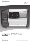
OPTYMATM Control
Single-phase
REFRIGERATION &
aIR CONDITIONING DIVISION
Operation and Maintenance Guide
OPTYMATM Control single-phase
Operation and Maintenance Guide
Table of contents
Page
General......................................................................................................................................................................................................4
Description..........................................................................................................................................................................................4
Applications........................................................................................................................................................................................4
Main characteristics.........................................................................................................................................................................4
Overall dimensions.............................................................................................................................................................................4
Identification data...............................................................................................................................................................................5
Installation..............................................................................................................................................................................................5
Important information for the installer....................................................................................................................................5
Standard assembly kit.....................................................................................................................................................................5
Installing the unit..............................................................................................................................................................................6
Functions.................................................................................................................................................................................................8
Technical characteristics of OPTYMATM Control, single-phase.......................................................................................8
Control panel.........................................................................................................................................................................................9
Front keypad.......................................................................................................................................................................................9
LED Display...................................................................................................................................................................................... 10
General.............................................................................................................................................................................................. 10
Symbols used.................................................................................................................................................................................. 10
Setting and displaying the set points..................................................................................................................................... 10
Level 1 - Programming (User Level)........................................................................................................................................ 11
List of Level 1 variables (User Level)........................................................................................................................................ 11
Level 2 - Programming (Installer Level)................................................................................................................................. 12
List of Level 2 variables (Installer Level)................................................................................................................................. 12
Switching on the OPTYMATM Control single-phase........................................................................................................... 13
Compressor activation/deactivation conditions................................................................................................................ 13
Manual defrosting......................................................................................................................................................................... 13
Hot-gas defrosting........................................................................................................................................................................ 14
Pump-down function................................................................................................................................................................... 14
Password function......................................................................................................................................................................... 14
Alarm relay........................................................................................................................................................................................... 15
Trouble shooting / Alarm list....................................................................................................................................................... 16
Connection diagrams...................................................................................................................................................................... 17
Parts list................................................................................................................................................................................................. 19
Ordering................................................................................................................................................................................................ 19
© Danfoss A/S Jan. 2010
RS8FD302, 080R9277
3
OPTYMATM Control single-phase
Operation and Maintenance Guide
General
Description
The OPTYMATM Control single-phase is a new control
panel for cold rooms with a single-phase compressor
up to 2 HP, specially designed for safety, protection,
control and ease of installation.
It allows the user to control all the components on
a refrigeration system: compressor, evaporator fans,
defrosting elements, room light and thermostatholder.
Applications
- Complete management of single-phase static
or ventilated refrigeration systems up to 2 HP, with
off-cycle or electrical defrosting and with direct or
pump-down compressor stop.
- Control of single-phase evaporator unit only with
solenoid valve or remote condensing unit.
Main characteristics
- Direct control of defrosting elements, evaporator
fans, room light with outputs directly connectable
to the various units.
- Automatic fuse protect the refrigeration unit.
- Stylish ABS housing with transparent cover for
access to the automatic fuse, all with an IP65
protection rating so that panel can be used
outside the room.
- LED indicators and large display show system
status.
- User-friendly keypad.
- Display resolution to 0.1 °C.
Overall dimensions
Dimensions in mm.
4
RS8FD302, 080R9277
© Danfoss A/S Jan. 2010
OPTYMATM Control single-phase
Operation and Maintenance Guide
Identification data
The unit described in this manual has an ID label on
the side showing all the relevant identification data:
•
•
•
•
•
•
Name of Manufacturer
Type and code number
Product name
Power supply
Serial number (10 digits)
Date (Day/Month/Year)
Installation
Important information for the installer.
Installation to be done by authorised person only!
1. Install the device in places where the protection
rating is observed and try not to damage the
housing when drilling holes for wire penetrations
5. Fit a general protection fuse before the electronic
controller.
6. All wiring must be of a diameter suitable for
relevant power levels.
2. Do not use multi-polar cables which have
wires connected to inductive/power loads and
signalling wires (e.g. sensors and digital inputs).
7. If a sensor extension is required, the wires
must have a diameter of at least 1 mm2.
3. Do not fit power supply wiring and signal wiring
(sensors and digital inputs) in the same
raceways or ducts.
4. Minimise the length of connector wires so that
wiring does not twist into a spiral shape as this
could have a detrimental effect on the electronics.
Standard assembly kit
For the purposes of assembly and use, the electronic
OPTYMATM Control single-phase unit comes with:
• Three rubber washers, to be fitted between the
fixing screws and the housing back panel
• One user’s manual.
• Two temperature sensors
© Danfoss A/S Jan. 2010
RS8FD302, 080R9277
5
OPTYMATM Control single-phase
Operation and Maintenance Guide
Installing the unit
1.
Lift the transparent cover.
Remove the screw cover on the
right-hand side of the housing.
2.
Undo the 4 fixing screws at the
front of the housing.
3.
Open the front of the housing, lift
it and slide the two hinges out as
far as they will go.
4.
Press on the sides of the hinges
to remove them from their seats
and then remove the front panel
completely.
6
RS8FD302, 080R9277
© Danfoss A/S Jan. 2010
OPTYMATM Control single-phase
Operation and Maintenance Guide
5.
Use the three existing holes to
fix the housing back panel to the
wall: use three screws of a suitable
length for the thickness of the
wall on which the panel will be
mounted. Fit a rubber washer
(supplied) between each screw
and the housing back panel.
6.
Hook the front panel back up to
the lower part of the housing by
inserting the two hinges in their
seats and, bending them, rotate
downwards 180° to gain access to
the electronic board.
NOTE !
Make all the electrical connections as illustrated in the diagram for the corresponding model (see
drawing on page 17).
To effect correct electrical connection and maintain the protection rating, use appropriate wire/
raceway grips to ensure a good seal.
Route the wiring inside the unit in as tidy a fashion as possible: be especially careful to keep power
wires away from signal wires. Use clips to hold wires in place.
7.
Close the front panel, making sure
that all the wires are inside the
housing and that the housing seal
sits in its seat properly.
Tighten the front panel using the 4
screws, making sure the O-rings on
the head of each screw are used.
Power up the panel and carry out
thorough reading/programming
of all the parameters.
NOTE !
Be careful not to over-tighten the closure screws as this could warp the housing and compromise
proper operation of the membrane-type keypad.
Install short-circuit overload safety devices on all the power cables connected to the OPTYMATM
Control so as to prevent damage to the device. Work and/or maintenance must be carried out on
the unit ONLY after disconnecting the panel from the power supply and from any inductive/power
loads: doing so allows the worker to do his job safely.
© Danfoss A/S Jan. 2010
RS8FD302, 080R9277
7
OPTYMATM Control single-phase
Operation and Maintenance Guide
Functions
OPTYMATM Control single-phase:
-
-
-
-
Display and adjustment of cold room temperature
setting to 0.1 °C
Display of evaporator temperature from parameter
System control activation/deactivation
System warnings (probe/sensor errors, minimum
and maximum temperature warnings, compressor
shutdown)
-
-
-
-
-
Evaporator fans control
Automatic and manual defrost (static, heating
element, cycle inversion)
Direct control of compressor unit up to 2 HP
Room light, via panel key or door switch
Alarms/auxiliary relay
Technical characteristics of OPTYMATM Control single-phase
Power supply
Voltage
230 V~ ± 10% 50Hz / 60Hz
Power consumption (electronics only)
~ 7 VA
Cold room conditions
Operating temperature
-5 to 50°C
Storage temperature
-10 to 70°C
Relative humidity
Less than 90% Not condensed. No shock influence/vibration.
General characteristics
Type of sensors
EKS 221, code no.: 084N3210
Resolution
0.1 °K
Sensor read precision
± 0.5 °K
Read range
-45…+45 °C
Digital inputs
Requirements to contact
Gold plating
OPTYMATM Control single-phase - Output characteristics - max. applicable load (230 V AC)
Compressor
1500W (AC3)
Defrost
3000W (AC1)
Fans
500W (AC3)
Room light
800W (AC1)
Alarm contact (non-powered contact)
100W
General electrical protection
Automatic fuse 16A
Id=300 mA
Disconnecting power 4.5 kA
Dimensions
Dimensions
168 mm x 97 mm x 262 mm (HxPxL)
Insulation / mechanical characteristics
8
Housing protection rating
IP65
Housing material
Self-extinguishing ABS
Type of insulation
Class II
RS8FD302, 080R9277
© Danfoss A/S Jan. 2010
OPTYMATM Control single-phase
Operation and Maintenance Guide
Control Panel
Front keypad
AUXILIARY RELAY CONTROL
(on the version with alarm relay controls the relay
manual if parameter AU=1)
UP / MUTE WARNING BUZZER
STAND BY
(The LED flashes if the system shuts down)
© Danfoss A/S Jan. 2010
Room temperature SETTING / SET key
DOWN / MANUAL DEFROST
ROOM LIGHT
RS8FD302, 080R9277
9
OPTYMATM Control single-phase
Operation and Maintenance Guide
LED Display
1. Cold room temperature / parameters
2. Stand-by (flashes on stand-by). Outputs are de activated
3. Room light (flashes if door switch activated)
4. Cold (indicates activation of compressor)
5. Fans
6. Defrosting
7. Auxiliary
8. Alarm/warning
General
To enhance safety and simplify the operator’s work,
the OPTYMATM Control has two programming
levels; the first level (Level 1) is used to configure
the frequently-modified SETPOINT parameters. The
second programming level (Level 2) is for general
parameter programming of the various controller
work modes.
It is not possible to access the Level 2 programming
directly from Level 1: you must exit the programming
mode first.
Symbols used
For practical purposes the following symbols are used:
• (▲) the UP key • (▼) the DOWN key
is used to increase values and mute the alarm.
is used to decrease values and force defrosting.
Setting and displaying the setpoints
1. Press the SET key to display the current SETPOINT
(temperature)
2. Hold down the SET key and press the (▲) or (▼)
keys to modify the SETPOINT.
Release the SET key to return to cold room
temperature display: the new setting will be saved
automatically.
10
RS8FD302, 080R9277
© Danfoss A/S Jan. 2010
OPTYMATM Control single-phase
Level 1 - Programming (User Level)
To gain access to the Level 1 configuration menu
proceed as follows:
1. Press the (▲) and (▼) keys simultaneously and
keep them pressed for a few seconds until the first programming variable appears on the display.
Operation and Maintenance Guide
When configuration values have been set, you
can exit the menu by pressing the (▲) and (▼)
keys simultaneously for a few seconds until the
cold room temperature reappears.
5. The new settings are saved automatically when
you exit the configuration menu.
2. Release the (▲) and (▼) keys.
3. Select the variable to be modified using the (▲)
and (▼) key.
4. When the variable has been selected it is
possible to:
• display the setting by pressing the SET key
• modify the setting by pressing the SET key
together with the (▲) and (▼) key.
List of Level 1 variables (User Level)
Variables
Explanation
Value
Default
r0
Differential above main SETPOINT*
* SETPOINT see page 10
0.2 - 10 K
2K
d0
Defrost interval (hours)
0 - 24 hours
4 hours
d2
End-of-defrost setpoint.
Defrosting will not take place if the temperature detected by the defrost
sensor is greater than d2 (If the sensor is faulty defrosting is timed)
-35 - 45 °C
15°C
d3
Max defrost duration (minutes)
1 - 240 min
25 min
d7
Drip duration (minutes)
At the end of defrost, the compressor and fans remain at standstill for time
d7 and the defrost LED on the front panel flashes.
0 - 10 min
0 min
F5
Fan pause after defrost (minutes)
Allows fans to be kept at standstill for time F5 after dripping. This time
begins at the end of dripping. If no dripping has been set, the fan pause
starts directly at the end of defrost.
0 - 10 min
0 min
A1
Minimum temperature alarm
Allows user to define a minimum temperature for the room being
refrigerated. Below value A1 an alarm trips: the alarm LED flashes, the
displayed temperature flashes and the buzzer sounds to indicate the
problem.
-
-45°C
A2
Maximum temperature alarm
Allows user to define a maximum temperature for the room being
refrigerated. Above value A2 an alarm trips: the alarm LED flashes, the
displayed temperature flashes and the buzzer sounds to indicate the
problem.
-
+45°C
tEu
Evaporator sensor temperature display
Displays
read
evaporator
only
temperature
(displays
nothing if
dE =1)
© Danfoss A/S Jan. 2010
RS8FD302, 080R9277
11
OPTYMATM Control single-phase
Operation and Maintenance Guide
Level 2 - Programming (Installer Level)
To access the second programming level press the
UP (▲) and DOWN (▼) keys and the LIGHT key
simultaneously for a few seconds.
When the first programming variable appears the
system automatically goes to stand-by.
1. Select the variable to be modified by pressing the
UP (▲) and DOWN (▼) keys.
When the parameter has been selected it is
possible to:
4. When configuration settings have been
completed you can exit the menu by pressing the
(▲) and (▼) keys simultaneously and keep them
pressed until the room temperature reappears.
5. Changes are saved automatically when you exit
the configuration menu.
6. Press the STAND-BY key to enable electronic
control.
2. View the setting by pressing the SET key.
3. Modify the setting by holding the SET key down
and pressing the (▲) or (▼) key.
List of Level 2 variables (Installer Level)
Variables
Explanation
Value
Default
AC
Door switch status
0 = normally open
1 = normally closed
0
F3
Fan status with compressor off
0 = fans run continuously
1 = fans only run when compressor is working
1
F4
Fan pause during defrost
0 = fans run during defrost
1 = fans do not run during defrost
1
dE
Sensor presence
If the evaporator sensor is disabled defrosts are
carried out cyclically with period d0: defrosting
ends when an external device trips and closes the
remote defrost contact or when time d3 expires.
0 = evaporator sensor present
1 = no evaporator sensor
0
d1
Defrost type, cycle inversion (hot gas) or with
heater elements
1 = hot gas
0 = electric
0
Ad
Not to be used
Ald
Minimum and maximum temperature
Signalling and alarm display delay
1…240 min
120 min
C1
Minimum time between shutdown and
subsequent switching on of the compressor.
0…15 min
0 min
CAL
Correction of sensor signal
-10…+10
0
Pc
Compressor protection contact status
0 = NO
1 = NC
0 = NO
doC
Compressor safety time for door switch: when
the door is opened the evaporator fans shut down
and the compressor will continue working for time
doC, after which it will shut down.
0…5 minutes
0
tdo
Restart time, if the door remains open
0... 240 min. (0=no function)
0
Fst
FAN shutdown TEMPERATURE
The fans will stop if the temperature value read by
the evaporator sensor exceeds this value.
-45…+45°C
+45°C
12
RS8FD302, 080R9277
© Danfoss A/S Jan. 2010
OPTYMATM Control single-phase
Operation and Maintenance Guide
Continued...
Variables
Explanation
Value
Default
Fd
Fan differential below Fst
0…+10K
2K
LSE
Min. limit of set point setting
-45...HSE
-45°C
HSE
Max. limit of set point setting
45... LSE
45°C
tA
NO – NC alarm relay switching
0 = activates when alarm is on
1 = deactivates when alarm is on
1
AU
Auxiliary/alarm relay control
0 = alarm relay
0
1 = manual auxiliary relay controlled via AUX key
2 = automatic auxiliary relay managed by StA temp. setting with 2°C differential
3 = not used
4 = pump-down function (see 5.15)
5 = free voltage contact for condensing unit (AUX relay and compressor relay in parallel)
6 = Relay used to control a heating
element in the crankcase.
The relay is on when the
compressor is stopped.
7 = not used
StA
Temp. setting for aux. relay
-45…+45°C
0
In1
Man in cold room alarm
Select input INP1 on the board as compressor
protection alarm or as man-in-room alarm
(contact NC).
0 = compressor protection
1 = man-in-room alarm
0
P1
Password type of protection
( active when PA does not equal 0)
0 = display set point only
1 = display set point, AUX, light access
2 = access to programming not permitted
3 = access to second level programming not permitted
3
PA
Password
(see P1 for the type of protection)
0...999
0 = not active
0
reL
Software release
indicates software version
Read
only
Switching on the OPTYMATM Control single-phase
After wiring the electronic controller correctly,
connect 230 V a.c.; the display panel will
immediately emit a beep and all the LEDs will come
on simultaneously for a few seconds.
Compressor activation/deactivation conditions
The OPTYMATM Control single-phase activates the
compressor when cold room temperature exceeds
setting+differential (r0); it deactivates the
compressor when the cold room temperature is
lower than the setting.
Manual defrosting
To defrost just press the dedicated key (see page 9)
to activate the elements relay. Defrosting will not
take place if the end-of-defrost temperature setting
(d2) is lower than the temperature detected by the
evaporator sensor. Defrosting ends when the endof-defrost temperature (d2) or maximum defrost
time (d3) is reached.
© Danfoss A/S Jan. 2010
RS8FD302, 080R9277
13
OPTYMATM Control single-phase
Operation and Maintenance Guide
Hot-gas defrosting
Set parameter d1 =1 to defrost in cycle inversion
mode.
The compressor relay and defrost relay are activated
throughout the defrost phase.
To ensure proper control of the system the installer
must use the defrost output: this must allow
opening of the cycle inversion solenoid valve and
closure of the liquid solenoid valve.
For capillary systems (without thermostat valve) the
cycle inversion solenoid valve can be controlled via
the defrost relay control.
Pump-down function
Pump-down function is activated when parameter
AU=4 (for version with AUX/Alarm relay only).
Connect pump-down pressostat on the digital input
INP-1.
The compressor is directly controlled by pressostat.
Connect evaporator solenoid valve on the AUX
relay. The solenoid is controlled directly by the
thermostat.
Password function
The protection function is activated when
parameter PA is set to a value other than 0.
See parameter P1 for the different protection types.
When PA is set, protection starts after two
minutes of inactivity. 000 appears on the display.
Use the up/down keys to change the number, and
the set key to confirm it. If you have forgotten your
password, use the universal number 100.
14
RS8FD302, 080R9277
© Danfoss A/S Jan. 2010
OPTYMATM Control single-phase
Alarm relay
Operation and Maintenance Guide
(Only pay attention to these instructions if alarm/aux relay is not functioning)
1. Open the front of the housing as described
on page 6: rotate it downwards 180° to gain
access to the electronic board.
2. Undo the 6 CPU board fixing screws: remove the
board from the front part of the housing in ABS.
3. Remove the jumper from JUMPER JP2.
4. Insert the jumper in JUMPER JP2 in position 2-1 to
select Alarm relay.
© Danfoss A/S Jan. 2010
RS8FD302, 080R9277
15
OPTYMATM Control single-phase
Operation and Maintenance Guide
Trouble shooting / Alarm list
In the event of any anomalies the OPTYMATM Control
warns the operator by displaying alarm codes and
sounding the warning buzzer inside the control
panel. If an alarm is tripped the display will show one
of the following messages.
Alarm code
Possible cause
Solution
E0
Cold room temperature sensor not working
properly
• Check that cold room temperature sensor is
working properly
• If the problem persists replace the sensor
E1
Defrost sensor not working properly
(In this case defrosts will last time d3)
• Check that defrost sensor is working properly
• If the problems persists replace the sensor
E2
Eeprom alarm
• Switch unit off and then back on again
An EEPROM memory alarm has been detected
(All outputs except the alarm one are
deactivated)
E8
Man-in-room alarm
• Reset the alarm input inside the cold room
Ec
Compressor protection tripped (e.g. thermal
protection or max pressure switch)
(All outputs except the alarm one – where
applicable – are deactivated)
•
•
•
Ed
Open door - alarm (Open door and tdo-time
has expired)
Check door / door contact
Temperature
shown on
display is
flashing
Minimum or maximum temperature alarm.
The temperature inside the cold room has
exceeded the min. or max. temperature
alarm setting (see variables A1 and A2, user
programming level)
•
•
16
RS8FD302, 080R9277
Check that compressor is working properly
Check compressor absorption
If the problem persists contact the technical assistance
Check that the compressor is working properly.
Sensor not reading temperature properly or compressor start/stop control not working.
© Danfoss A/S Jan. 2010
OPTYMATM Control single-phase
Operation and Maintenance Guide
© Danfoss A/S Jan. 2010
Common
9 10
RS485-A
RS485-B
Defrost probe
Ambient probe
Common probe
Common dig. input
Door Limit Switch
Comp. Protection
1 2 3 4 5 6 7 8
Power
Supply
230Vac
11 12 13
14 15
16 17 18 19
Connection diagram
Not to be used
RS8FD302, 080R9277
17
OPTYMATM Control single-phase
Operation and Maintenance Guide
How to connect the OPTYMATM Control single-phase to OPTYMATM condensing unit
RS485-A
RS485-B
Defrost probe
Ambient probe
Common probe
Common dig. input
Door Limit Switch
Comp. Protection
1 2 3 4 5 6 7 8
Power
Supply
230Vac
9 10
11 12 13
14 15
16 17 18 19
Not to be used
OPTYMATM Condensing unit
HP
Condenser Compressor
fan
How to connect the OPTYMATM Control single-phase to OPTYMA PLUSTM condensing unit
RS485-A
RS485-B
Defrost probe
Ambient probe
Common probe
Common dig. input
Door Limit Switch
Comp. Protection
1 2 3 4 5 6 7 8
Not to be used
18
Power
Supply
230Vac
9 10
11 12 13
14 15
16 17 18 19
Terminals:
4 and 5 on housing 1, 2 and 3
5 and 6 on housing 4
6 and 7 on housing 3 (Nordic 230V-3-50Hz)
RS8FD302, 080R9277
© Danfoss A/S Jan. 2010
OPTYMATM Control single-phase
Operation and Maintenance Guide
Parts list
1
Housing back panel in ABS
2
Housing front panel in ABS
3
Front cover in transparent polycabonate
4
Front panel opening hinge
5
Front panel closure screws
6
Board fixing screws
7
Automatic fuse/ Cut out switch
8
CPU board
9
Polycarbonate screw cover
10
Terminal for earth connections
Ordering
Type
Code no.
OPTYMATM Control single-phase (2 HP)
including two sensors
080Z3200
Sensor EKS 221 (spare part)
084N3210
© Danfoss A/S Jan. 2010
RS8FD302, 080R9277
19
Notes
20
RS8FD302, 080R9277
© Danfoss A/S Jan. 2010