1
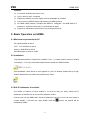
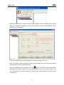
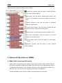
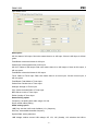
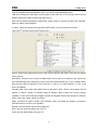
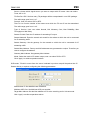
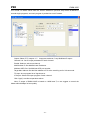
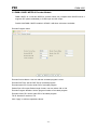
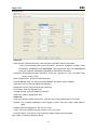
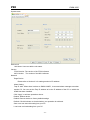
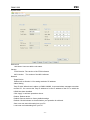
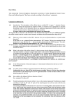
Digital CATV Head End Modular Bank
User Manual
(ver. A)
http://www.pbi-china.com
目
录
1. SUMMARY ............................................................................................................1
2. BASIC OPERATION ON HDMS ............................................................................2
2.1 Minimum requirements for PC .............................................................................2
2.2 Installation............................................................................................................2
2.3 Edit IP addresses of modules ..............................................................................2
3. ADVANCED OPERATION ON HDMS....................................................................4
3.1 DMM-1300P Professional IRD module ................................................................4
3.2 DMM-1300EC MPEG-2 Encoder Module ..........................................................12
3.3 1300MX Re-Multiplexer Module.........................................................................15
3.4 1300TM Modulator Module ................................................................................18
3.5 Alarms management ..........................................................................................22
4. FAQ .....................................................................................................................23
PBI
DMM-1000
DMM-1000 Digital CATV Head End Modular Bank
1. Summary
DMM-1000 is a digital CATV head end modular bank, which combines modularized
professional IRD, MPEG-2 encoder, Re-Multiplexer and QAM/COFDM Modulator into a
4Ux19” chassis. User can use it to build up a mini digital headend system easily. It is
controlled by HDMS (a remote software developed by PBI) via LAN. The flexibility and
easy-to-use of DMM-1000 present a highly integrated and stable digital CATV system
solution.
Model No.
DMM-1000MF
DMM-1300P
DMM-1300EC
DMM-1300MX
Description
Main Frame
Professional IRD module
MPEG-2 encoder module
Re-Multiplexer module
DMM-1300TM
DMM-1300CM
QAM Modulator module
COFDM Modulator module
The DMM-1000 system block is shown as below:
Ethernet
Tuner signal: DVB-S2
Tuner signal: DVB-S
IP
ASI
1300P-S2
……….
IP
1300P-S
……….
HFC signal: DVB-C
ASI
IP
1300P-C
……….
COFDM signal: DVB-T
ASI
IP
1300P-T
ASI
1300MX
ASI IN1
ASI IN8
Analog signal:
MUX
ASI
~
CATV
network
1300TM
RF
QAM or
COFDM
modulate
CVBS/ Analog Audio
Analog signal:
1300EC
……….
CVBS/ Analog Audio
1300EC
ASI
ASI
LAN
LAN
HUB or Switch
-1-
LAN
PC
HDMS
PBI
DMM-1000
Features:
◎
4U chassis, flexibility and easy-to-use.
◎
Up to 9 slots for max. 9 modules
◎
Support hot backup for power supply and hot-swappable for modules.
◎
LAN control by HDMS software which based on SNMP protocol.
◎
For DMM-1300P module, it complies with MPEG-2(MP@ ML)and DVB-S2/S/-C/-T
standard. It supports Unicast and 7-way Multicast IP output.
◎
Support fan temperature control which can prolong its lifecycle.
2. Basic Operation on HDMS
2.1 Minimum requirements for PC
OS: Windows2000 or above
CPU:
PIII / 800 MHz or above
Memory: 256M DDR or above
Hard disk space: more than 100M.
2.2 Installation
Login Windows platform. Double click “HDMS***.exe”( “***”means version number of HDMS,
for example, “2.14.1Lite”) and follow install wizard to install the HDMS software.
After installation, there will be an icon appears on your PC desktop, double-click it to login
HDMS. Both default user name and password are “hdms”.
2.3 Edit IP addresses of modules
The default IP address of each module is 10.10.70.48, thus you firstly should set IP
addresses of modules one by one avoid IP address conflict.
Connect your PC with DMM-1000. Set the IP address of your PC to10.10.70.xx(xx means a
number beside 1, 256 and 48). Login HDMS, Click the
detected by HDMS.
-2-
button, the module will be
PBI
DMM-1000
Double click the device, it will show the submenu as below. Choose “System” menu, change
Device IP to another IP address, then click “Apply” button to confirm your operation. The IP
address is set successfully.
Follow this method above to set IP addresses of other modules one by one.
Note: It is better to use independent LAN to control DMM-1000. That will reduce failures
which caused by lack of network resource.
After set IP addresses of all modules, click the
button, all devices will be automatically
detected. If the device is green color, that means HDMS connect to the device well. If red
color, means fail to connect to the device. If yellow color, means HDMS is trying to connect
to the device.
-3-
PBI
DMM-1000
There are some introductions about icons in HDMS:
connect the network, click this button, HDMS will detect
devices in the LAN automatically.
lock screen, click this button, HDMS will be locked. User
cannot do any operations until login as Admin to unlock this
status.
Search devices in LAN, click this button to searching
devices in LAN manually.
Check device status. Click this button, HDMS will ping
each device in LAN to check their working status.
Delete device,click this button to delete the device in list.
Set email configuration, click this button to set email
forwarding function when alarm.
Review Alarm history. Click this button to check alarm
record.
Network topology, click this button to show network
topology diagram.
3. Advanced Operation on HDMS
3.1 DMM-1300P Professional IRD module
DMM-1300P is a professional IRD module, which supports QPSK, QAM, COFDM, DVB-S2
and ASI input (different models). Each DMM-1300P has a CI slot for CAM to decrypt various
Conditional Access Systems, such as Irdeto, Viaccess, Conax, PowerCAM and SMiT etc. It
also can convert TS to IP format. It supports Unicast and 7-way Multicast.
Double click DMM-1300P module in HDMS, it will show sub-menus as below:
-4-
PBI
DMM-1000
Input Status menu
State option
ASI IN: Status of ASI input. Red color means there is no ASI input. If there is ASI input, it will turn
green.
Total Bitrate: shows the bitrate of ASI input
Packet Size: shows packet size of ASI input
ASI OUT: Status of ASI output. Red color means there is no ASI output. If there is ASI output, it
will turn green.
Total Bitrate: shows the bitrate of ASI output
Tuner: Status of Tuner input. Red color means there is no tuner input. If there is tuner input, it
will turn green.
Total Bitrate: Total bitrate of Tuner input
Packet Size: Packet size of Tuner input
Strength: Strength of Tuner input
C/N: Carrier-to-Noise Ratio of Tuner input
BER: Bit error ratio of Tuner input
Eb/No: Quality of Tuner input
Status Polling option
Frequency: set pulling time within range of 5-30s.
Done: refresh status polling.
QPSK setting option
LNB Freq: sets the LNB Local Oscillator (L.O.) frequency
Sat Freq: sets satellite downlink frequency
Symbol Rate: sets symbol rate
LNB Voltage: selects correct LNB voltage: Off, 13V, 18V (Usually, 13V switches the LNB to
-5-
PBI
DMM-1000
receive Vertical/Left hand polarization while 18V receive Horizontal/Right hand)
LNB 22K: activate the LNB 22kHz control signal to the LNB: On or Off (Usually, 22KHz control
signal switches the LNB to receive high band if any)
After set the relative parameters, please click “Apply” button to confirm and then click “Refresh”
button to obtain current settings
CI menu. When user wants to decrypt with CAM module, you can enter this sub-menu.
Source: Select input signal source which user wants to decrypt with CAM. There are two options:
Tuner and ASI.
Slot1/Slot2: There are two CI slots on DMM-1300P, but one slot is for backup, user cannot use
two CAM modules at the same time. When user insert CAM module into CI slot of DMM-1300P,
there will be CAM info appears in this sub-menu. If there is no CAM module in CI slot, it will
show “No Module”
Program table: After select input signal source and press “Apply” button, the program list will
appear. In “Select” column, the default setting is “Bypass” which means don’t do any decrypt
operation. If user want to decrypt program, double click Bypass column and change it to Slot1(or
Slot2). Then click “Apply” button to confirm.
Apply: this button is used to confirm your operation. When you make any settings, you need to
click this button to confirm your operation.
Refresh: click this button will refresh program list.
Save: user can save this setting into your PC.
Load: user can load setting from your PC.
-6-
PBI
DMM-1000
ASI Output menu, when user wants to output ASI signal, you can enter this sub-menu.
Source: signal source of ASI output selection, user can select Tuner, ASI or CI. If select Tuner,
DMM-1300P will output programs in ASI output port directly without any decryption.
Packet Size: ASI output packet size setting; user can select 188 or Bypass
Click “Apply” to achieve operations above.
Refresh: Click this button to check whether your operation is achieved.
Save: user can save this setting into your PC.
Load: user can load setting from your PC.
Decoder Output menu. When user wants to output AV signal, you can enter this sub-menu
-7-
PBI
DMM-1000
Decoder Play
Source: choose which signal source you want to decode. User can select Tuner, ASI or CI.
Program: After select Source, the program list of this source will appear. Select one
program that you want to decode, click “Apply” button to confirm.
Video Output
Video Standard: User can select Auto, PAL, NTSC or SECAM.
Screen: Video screen display option. User can select Auto, 4:3 Full, 16:9 Full or 16:9 Full.
DVB Subtitle Lang: select DVB Subtitle language
EBU Subtitle Lang: select EBU Subtitle language
Subtitle Priority: configure the priority of subtitle. User can select DVB First or EBU First.
Fail Mode: It includes Black Screen, No Sync and Still Picture
Biss Info
Biss Mode: It includes OFF, Biss E and Biss 1
Biss 1 Setup: Set Biss 1, password is required
Biss E Setup: Set Biss E, ID number and password are required
Audio Output
Audio Level:
It can be adjusted in the range of 0 to 99.
Audio Mode:
User can select Stereo, Left, Right or Mono for soundtracks,
Audio Language
Click “Apply” to achieve operations above.
IP Output menu. When user wants to output IP signal, you can enter this sub-menu
-8-
PBI
DMM-1000
Source: choose which signal source you want to output with IP format. User can select
Tuner, ASI or CI.
TS Pkts Per UDP: Set how many TS packages will be encapsulated in one UDP package.
The valid range goes from 1 to 7.
Protocol: User can select UDP or RTP.
Time To Live: Set the number of the routers over which the TS over IP can be transmitted.
The valid range goes from 1 to 5.
Type of Service: User can select Normal, Min Monetary Cost, Max Reliability, Max
Throughput or Min Delay.
Stream IP Addr: Enter the IP address for streaming IP output.
Stream Netmask: Enter the network sub mask for the subnet to which the unit is connected
for IP streaming traffic.
Stream Gateway: Set the gateway for the network to which the unit is connected for IP
streaming traffic.
Stream Mac Address: Factory-set MAC addresses are guaranteed to unique. Therefore you
cannot configure the address.
Gateway Mac Address: Set gateway Mac Address
Mode: Select the mode of IP stream output, user can select DVB or IPTV.
Click “Apply” to achieve operations above.
DVB mode: TS which comes from the ‘source’ selected in previous step will be packed into IP
Stream directly. It requires configuring the following parameters.
Multi/Unicast IP: Set Multi/Unicast IP address.
Multicast UDP Port: Set Multicast UDP port number.
Target Mac Address: Set the Mac address of PC at the receiving end in Unicast mode.
Click “Apply” to achieve operations above.
-9-
PBI
DMM-1000
IPTV mode: TS which comes from the ‘source’ selected in previous step will be de-Muxed to
several single programs, and each program is packed into one IP stream.
Output: Select IP TV outputs 1~7,it supports maximum 7-way Muliticast IP output.
Channel 0~6: Set IP output parameters of each channel.
Enable: Select to active one channel.
Multi/Unicast IP: Set Multi/Unicast IP address.
Multicast UDP Port: Set Multicast UDP port number.
Target Mac Address: Set the Mac address of PC at the receiving end in Unicast mode.
TS Input: show program list of signal source.
IP Output: Select the output program of each channel.
Click “Apply” to achieve operations above.
Note: IP output of DMM-1300P is based on 100M base-T, so we suggest to control the
bitrate within 80Mbps for best quality.
- 10 -
PBI
DMM-1000
System menu. User can edit IP address and check some info about device.
Device Info
Unit Name: User can edit the unit name.
Version
FPGA Version: The version of the FPGA software
MCU Version:
The version of the MCU software
Network
Target Device
Please refer to Section 2.3 for setting method of IP address.
Alarm Setting
Trap IP Addr: When there is alarm on DMM-1300P, it can send alarm message to another
monitor PC. You can set the Trap IP address to be the IP address of the PC on which the
HDMS has been installed.
Click “Apply” to achieve operations above.
Reboot: Reboot device.
Default: Recover device to factory default settings
Refresh: Click this button to check whether your operation is achieved.
Save: user can save this setting into your PC.
Load: user can load setting from your PC.
- 11 -
PBI
DMM-1000
3.2 DMM-1300EC MPEG-2 Encoder Module
DMM-1300EC is a real time MPEG-2 encoder which fully complies with ISO/IEC13818. It
supports SDI (audio embedded) or CVBS input and ASI output.
Double click DMM-1300EC module in HDMS, it will show sub-menus as below:
Encoder Program menu
Encoder Service Name: User can edit the encoded program’s name.
Encoder PMT PID: Set the PMT PID of encoded program.
Encoder Audio PID: Set the Audio PID of encoded program.
Packet Size: ASI output Packet length format, user can select 188 or 204.
Encoder Program Number: Set the program number of encoded program.
Encoder Video PID: Set the video PID of encoded program.
TS ID: Set the ID number of TS.
Click “Apply” to achieve operations above.
- 12 -
PBI
DMM-1000
Encoder menu
Video Info
Video Source: Video input source, user can select composite Video or SDI Video.
GOP: Used for setting GOP(group of pictures) structures. It supports 4 modes: IIIIIIIII,
IPPPPPPPP, IBIPBPBPB and IBBPBBPBB. The compression rate of the IBBPBBPBB
mode is the highest, followed by IBIPBPBPB, IPPPPPPPP and IIIIIIIII
Resolution: Represents the video resolution. There are 7 formats: D1, HD1, SIF, QSIF, Slice
screen, 2/3D1, 3/4D1
Mode: Supports PAL, NTSC and SECAM output.
Encoder BitRate: User can set the encoding BitRate, the default value is 5Mbit/s.
Saturation Control: User can adjust the saturation.
Brightness Control: User can adjust the brightness.
Hue Control: User can adjust the hue.
Contrast Control: User can adjust the contrast.
GOP Size: Used for setting GOP size.
Audio Info
Audio Input Source: Audio Input source, user can select Composite Audio or SDI Audio
Bit Rate: The occupied bandwidth of audio signal in output: 32K, 64K, 128K, 192K, 256K or
384K
Sample: Different sample rate: 32K, 44.1K or 48K.
Layer: The mode of MPEG-2 audio encode: Layer1 or Layer2.
Channel: Stereo, Joint Stereo, Dual Channel or single Channel as track Audio.
Click “Apply” to achieve operations above.
- 13 -
PBI
DMM-1000
System menu
Device Info
Unit Name: User can edit the unit name.
Version
FPGA Version: The version of the FPGA software
MCU Version: The version of the MCU software
Network
Target Device
Please refer to Section 2.3 for setting method of IP address.
Alarm Setting
Trap IP Addr: When there is alarm on DMM-1300EC, it can send alarm message to another
monitor PC. You can set the Trap IP address to be the IP address of the PC on which the
HDMS has been installed.
Click “Apply” to achieve operations above.
Reboot: Reboot device.
Default: Recover device to factory default settings
Refresh: Click this button to check whether your operation is achieved.
Save: user can save this setting into your PC.
Load: user can load setting from your PC.
- 14 -
PBI
DMM-1000
3.3 1300MX Re-Multiplexer Module
DMM-1300MX is a DVB TS re-Multiplexer, which supports 8 ASI Input and 2 ASI output
(one output port is for backup). It is based on PID exchange technology and can support
MPTS. It can detect Input packet length automatically, and allow user to configure output
packet length.
Double click DMM-1300MX module in HDMS, it will show sub-menus as below:
Input Status menu
Input Status:
Indicators for ASI 1-ASI 8 input status respectively.
Green: There is ASI input
Red: There is no ASI input
Total Bitrate: Input Bitrate of ASI input.
Valid Bitrate: Valid Bitrate of ASI input.
Click “Apply” to achieve operations above.
- 15 -
PBI
DMM-1000
Program Selection menu
Remove CA: If select this option, it will remove the CA descriptor in TS stream.
Transport NIT: If select this option, it will keep NIT in TS stream
TS ID: Set the ID of TS stream for distinguishing from other streams in the same system
Packet Size: Set the ASI packet Size, user can select 188 or 204 packet length.
Out Bit Rate: Set the total Bit rate for ASI output. Please ensure Our Bit rate is larger than Out
valid bitrate.
Out Valid BitRate: Set the Valid Bitrate for ASI output.
TS Input: Program list from ASI input. User can click “Refresh“button to refresh the list.
TS Output: Select the programs for ASI output.
Click “Apply” to achieve operations above.
- 16 -
PBI
DMM-1000
System menu
Device Info
Unit Name: User can edit the unit name.
Version
FPGA Version: The version of the FPGA software
MCU Version:
The version of the MCU software
Network
Target Device
Please refer to Section 2.3 for setting method of IP address.
Alarm Setting
Trap IP Addr: When there is alarm on DMM-1300MX, it can send alarm message to another
monitor PC. You can set the Trap IP address to be the IP address of the PC on which the
HDMS has been installed.
Click “Apply” to achieve operations above.
Reboot: Reboot device.
Default: Recover device to factory default settings
Refresh: Click this button to check whether your operation is achieved.
Save: user can save this setting into your PC.
Load: user can load setting from your PC.
- 17 -
PBI
DMM-1000
3.4 1300TM Modulator Module
1300TM is a full band adjacent agile DVB modulator for QAM or COFDM (depends on
different models). It can convert ASI signal to RF carrier. User can use its PID filtering
function to remove unnecessary programs to save bandwidth.
Double click DMM-1300TM module in HDMS, it will show sub-menus as below:
Input menu
Input Valid Bitrate: show valid Bitrate of ASI input.
Input Total Bitrate: show total Bitrate of ASI input.
- 18 -
PBI
DMM-1000
Filter menu
Enabled: Active PID filter function. When enable filter function, user can select program which
you want to filter out. If you don’t make any selection, it will output all programs in the
list.
Source: Select signal source which you want to filter programs. User can select Tuner, ASI or CI.
Research: When the input source is changed, click “Research” button to regenerate TS data,
then click “Refresh” button to get new program list.
Click “Apply” to achieve operations above.
- 19 -
PBI
DMM-1000
Output Menu
QAM Status
Normal:
Green light: means it modulate ASI signal to QAM signal normally with current settings.
Red light: Means overflow.
Valid Bitrate: show Valid Bitrate of ASI input.
Total Bitrate: show the max. Bitrate allowed under current settings.
Note: It is suggested to keep Valid Bitrate 3M smaller than total Bitrate for better
transmission.
QAM Setting
Frequency: Set output RF carrier frequency within range of 48~860MHz.
Symbol Rate: Symbol Rate for QAM modulation,the default value is 6875KBaud
QAM Constellation: User can select 16/32/64/128/256/64B/256B QAM.
RF Level: Adjustable within range of 97~110dB.
I/Q Inversion: Selecting “Yes” for Inverted I/Q, selecting “No” for non-inverted.
Modulation: Selecting QAM modulation. Selecting ON to activate QAM modulation and
selecting OFF to output single non-modulated carrier (for example, to measure
the channel power).
Click “Apply” to achieve operations above.
- 20 -
PBI
DMM-1000
System menu
Device Info
Unit Name: User can edit the unit name.
Version
FPGA Version: The version of the FPGA software
MCU Version:
The version of the MCU software
Network
Target Device
Please refer to Section 2.3 for setting method of IP address.
Alarm Setting
Trap IP Addr: When there is alarm on DMM-1300TM, it can send alarm message to another
monitor PC. You can set the Trap IP address to be the IP address of the PC on which the
HDMS has been installed.
Click “Apply” to achieve operations above.
Reboot: Reboot device.
Default: Recover device to factory default settings
Refresh: Click this button to check whether your operation is achieved.
Save: user can save this setting into your PC.
Load: user can load setting from your PC.
- 21 -
PBI
DMM-1000
3.5 Alarms management
When you set the Trap IP address to be the IP address of the PC on which the HDMS has been
installed. Click the
button, you can check all the alarm information in history record as
below.
- 22 -
PBI
DMM-1000
4. FAQ
1. Why cannot detect devices?
If device cannot be detected by HDMS, please check whether following items are
implemented correctly:
1)Can device be accessed through Ping order ?
Please make sure your PC can ping other devices successfully.
2)Is the IP address of device in the same LAN segments as HDMS?
Please make sure the IP address of device is in the same LAN segments as
HDMS. For example, if the IP address of the device is 10.10.70.48, you must set
IP address of the PC with HDMS to 10.10.70.xx (xx means a number beside 1,
256 and 48)
3)Are your PC only connected to one single network with device?
Please connect your PC installed HDMS to only one network with device.
4)Is there any other network management software installed in the PC?
Please make sure there is no other third party software based on SNMP protocol
being installed in the PC. If there is, please close it and ensure there is no other
software using SNMP protocol port.
5) Do you click
button after you login HDMS software?
button first when your login HDMS. Then it will detect device in
Please click
LAN automatically.
6)Is the software version of DMM-1000 capable with software version of HDMS?
Please make sure the software version of DMM-1000 can matches the HDMS
version, you can refer to the release notes or contact with PBI engineers.
2. Why cannot boot HDMS?
Is the HDMS software installed correctly? Please uninstall HDMS and then re-install
it to check whether you can boot it.
3. Why cannot login HDMS?
Please ensure your enter the correct user name and password. The initial user
name is: hdms, and password is: hdms.
- 23 -
Beijing Jaeger Communication Electronic Technology Co., Ltd.
Tel: 010-81617178
Fax: 010-82610263