1
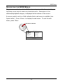
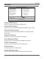
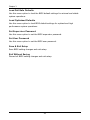
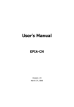
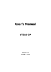
User’s Manual
EPIA-N
Version 1.04
November 11, 2005
Copyright
Copyright © 2004-2005 VIA Technologies Incorporated. All rights reserved.
No part of this document may be reproduced, transmitted, transcribed, stored in a
retrieval system, or translated into any language, in any form or by any means,
electronic, mechanical, magnetic, optical, chemical, manual or otherwise without the
prior written permission of VIA Technologies, Incorporated.
Trademarks
All trademarks are the property of their respective holders. PS/2 is a registered
trademark of IBM Corporation. AwardBIOS is a registered trademark of Phoenix
Technologies Ltd.
Disclaimer
No license is granted, implied or otherwise, under any patent or patent rights of VIA
Technologies. VIA Technologies makes no warranties, implied or otherwise, in
regard to this document and to the products described in this document. The
information provided in this document is believed to be accurate and reliable as of the
publication date of this document. However, VIA Technologies assumes no
responsibility for the use or misuse of the information in this document and for any
patent infringements that may arise from the use of this document. The information
and product specifications within this document are subject to change at any time,
without notice and without obligation to notify any person of such change.
FCC-B Radio Frequency Interference Statement
This equipment has been tested and found to comply with the limits for a class B
digital device, pursuant to part 15 of the FCC rules. These limits are designed to
provide reasonable protection against harmful interference when the equipment is
operated in a commercial environment. This equipment generates, uses and can radiate
radio frequency energy and, if not installed and used in accordance with the
instruction manual, may cause harmful interference to radio communications.
Operation of this equipment in a residential area is likely to cause harmful
interference, in which case the user will be required to correct the interference at his
personal expense.
Notice 1
The changes or modifications not expressly approved by the party responsible for
compliance could void the user's authority to operate the equipment.
Notice 2
Shielded interface cables and A.C. power cord, if any, must be used in order to comply
with the emission limits.
Tested To Comply
With FCC Standards
FOR HOME OR OFFICE USE
Safety Instructions
1.
Always read the safety instructions carefully.
2.
Keep this User's Manual for future reference.
3.
Keep this equipment away from humidity.
4.
Lay this equipment on a reliable flat surface before setting it up.
5.
The openings on the enclosure are for air convection hence protects the equipment
from overheating. DO NOT COVER THE OPENINGS.
6.
Make sure the voltage of the power source and adjust properly 110/220V before
7.
Place the power cord in such a way that people cannot step on it. Do not place
connecting the equipment to the power inlet.
anything over the power cord.
8.
Always unplug the power cord before inserting any add-on card or module.
9.
All cautions and warnings on the equipment should be noted.
10. Never pour any liquid into the opening. Liquid can cause damage or electrical
shock.
11. If any of the following situations arises, get the equipment checked by a service
personnel:
•
The power cord or plug is damaged
•
Liquid has penetrated into the equipment
•
The equipment has been exposed to moisture
•
The equipment has not work well or you cannot get it work according to
User's Manual.
•
The equipment has dropped and damaged
•
If the equipment has obvious sign of breakage
12. DO NOT LEAVE THIS EQUIPMENT IN AN ENVIRONMENT
UNCONDITIONED, STORAGE TEMPERATURE ABOVE 60 C (140F), IT
MAY DAMAGE THE EQUIPMENT.
CAUTION: Explosion or serious damage may occur if the
battery is incorrectly replaced. Replace only with the same or
equivalent battery type recommended by the manufacturer.
BOX CONTENTS
One
One
One
One
One
One
One
VIA Nano-ITX mainboard
Quick Installation Guide
ATA-66/100/133 IDE ribbon cable
PS2 cable
USB 2.0 4-port cable
ATX power cable adapter
driver and utilities CD
i
TABLE OF CONTENTS
Box Contents ..................................................................................... i
Table of Contents...............................................................................ii
Specifications .................................................................................... 1
Mainboard Specifications ................................................................ 2
Mainboard Layout .......................................................................... 4
Back Panel Layout .......................................................................... 5
Back Panel Ports ............................................................................ 6
Slots.............................................................................................. 6
Onboard Connectors....................................................................... 6
Onboard Jumpers........................................................................... 6
Installation ....................................................................................... 7
CPU............................................................................................... 8
Memory Module Installation ...........................................................10
Connecting the Power Supply ........................................................11
Back Panel Ports ...........................................................................12
Connectors ...................................................................................14
Jumpers .......................................................................................20
Slots.............................................................................................21
BIOS Setup ......................................................................................22
Entering Setup ..............................................................................23
Control Keys .................................................................................24
Navigating the BIOS Menus ...........................................................25
Getting Help .................................................................................26
Main Menu....................................................................................27
Standard CMOS Features ...............................................................29
IDE Drives ....................................................................................30
Advanced BIOS Features ...............................................................31
Hard Disk Boot Priority ..................................................................34
Advanced Chipset Features............................................................35
AGP & P2P Bridge Control..............................................................37
CPU & PCI Bus Control ..................................................................38
TV Output Connector.....................................................................39
Integrated Peripherals...................................................................40
Super IO Device............................................................................42
ii
Power Management Setup .............................................................43
Peripheral Activities.......................................................................45
IRQs Activities ..............................................................................48
PNP/PCI Configurations .................................................................49
IRQ Resources ..............................................................................51
PC Health Status ...........................................................................52
Frequency/Voltage Control ............................................................53
Load Fail-Safe Defaults..................................................................56
Load Optimized Defaults................................................................57
Set Supervisor/User Password........................................................58
Save & Exit Setup .........................................................................59
Exit Without Saving .......................................................................60
Driver Installation ............................................................................61
Driver Utilities ...............................................................................62
CD Content ...................................................................................64
iii
This page left intentionally blank.
iv
CHAPTER 1
Specifications
The ultra-compact and highly integrated VIA EPIA-N Nano-ITX
mainboard is the smallest form-factor available today. Through a high
level of integration, the Nano-ITX measures at only 50% of the size of
a Mini-ITX mainboard. The mainboard comes with an embedded VIA
Luke CoreFusion™ Processor that boasts of ultra-low power
consumption, space-saving package.
1
Chapter 1
MAINBOARD SPECIFICATIONS
Core Logic
•
VIA Luke CoreFusion™ Processor
•
VIA VT8237R-series South Bridge
Graphics
•
Integrated UniChrome™ Pro AGP
•
MPEG-2 decoding and MPEG-4 acceleration
Audio
•
VIA VT1617A 6-channel AC'97 codec
Memory
•
1 x DDR 266/333/400 SODIMM socket (up to 1 GB)
Expansion Slot
•
1 x Mini-PCI slot
•
1 x 40-pin UltraDMA 66/100/133 pin connector
•
1 x 44-pin UltraDMA 66/100/133 for secondary 2.0 mm pin connector
IDE
Serial-ATA
•
1 x Serial ATA connector
LAN
•
VIA VT6103 10/100 Base-T Ethernet PHY
TV-Out
•
VIA VT1625 HDTV Encoder
2
Specifications
Back Panel I/O Ports
•
1 x RJ-45 LAN port
•
2 x USB 2.0 ports
•
1 x VGA port
•
1 x RCA port (SPDIF or TV out)
•
1 x S-Video port
•
3 x Audio jacks: line-out, line-in and mic-in (supports 6-channels, see
Appendix A)
Onboard I/O Connectors
•
2 x USB pin headers for 4 additional USB 2.0 ports
•
1 x LVDS / DVI connector (an add-on card is required)
•
1 x YPbPr pin header (Component TV output connector)
•
1 x VIP pin header
•
1 x SIO pin header (including SIR and LPC support)
•
1 x KB/MS pin header
•
1 x Fan connector
•
1 x Nano-ITX power connector
BIOS
•
AwardBIOS with 4/8Mbit flash memory
Form Factor
•
Nano-ITX (8 layers)
•
12 cm X 12 cm
3
Chapter 1
MAINBOARD LAYOUT
PWR
SODIMM
Top: RCA Jack
Bottom: S-video
IDE1
Luke
CoreFusion
Processor
J2
JLVDS/DVI
JY3
JY2
JY1
Top: VGA-out
Bottom: Audio Jacks
IDE2
VT8237R-series
South Bridge
LVDS_DVI
SATA
BIOS
Socket
Top: RJ45 Port
Bottom: USB Ports
CPU
FAN
JSIO
JVIP
JUSB2
CMOS Battery
JUSB1
JKBMS
Mini-PCI on Bottom-side of Board CLEAR_CMOS
4
FPNL
Specifications
BACK P ANEL LAYOUT
VGA-out
RJ45
RCA-out
S-video
USB
Line-out
Line-in
5
Microphone
Chapter 1
BACK P ANEL PORTS
Port
Description
Audio jacks
RCA
RJ45
S-Video
USB
VGA
Line-out, line-in, microphone
RCA Video-out or SPDIF
RJ45 port
S-Video port
USB 2.0 ports
VGA-out port
Page
12-13
12
12-13
12
12-13
12
SLOTS
Port
Description
Mini PCI
SODIMM
Expansion card slot
Memory module slot
Page
21
10
ONBOARD CONNECTORS
Connector
Description
CPU FAN
F_PANEL
IDE 1-2
KB/MS
LVDS / DVI
Nano-ITX PWR
S-ATA
SIO
USB 1-2
VIP
YPBPR
CPU fan connector
Case connectors
IDE drive
Keyboard or mouse connector
LVDS connector
Power cable connector
Serial ATA drive connector
LPC / SIR connector
Universal Serial Bus connectors 1-2
VIP pin connector
Component TV output connector
Page
9
15
14
16
18
11
17
17
16
19
19
ONBOARD JUMPERS
Jumper
Description
CLEAR_CMOS
J2
LVDS_DVI
Reset CMOS settings
SPDIF and RCA Video
LVDS or DVI Video settings
Page
6
20
20
20
CHAPTER 2
Installation
This chapter provides you with information about hardware
installation procedures. It is recommended to use a grounded wrist
strap before handling computer components. Static electricity may
damage some components.
7
Chapter 2
CPU
The VIA EPIA-N Nano-ITX mainboard includes an embedded VIA Luke
CoreFusion™ Processor. The VIA Luke CoreFusion™ Processor provides ultralow power consumption and advanced thermal dissipation properties and
features a fanless design. The VIA Luke CoreFusion™ Processor requires only
a heatsink to provide sufficient cooling.
8
Installation
CPU Fan:
The CPU fan runs on +12V and maintains the system cooling. When
connecting the wire to the connectors, always be aware that the red wire
should be connected to the +12V. The black wire should be connected to
GND.
FAN_MCM is a switch that is used by high-quality fans to monitor the system
temperature and will automatically adjust according to the environment.
GND
+12V
FAN_MCM
9
Chapter 2
MEMORY MODULE INSTALLATION
The VIA EPIA-N Nano-ITX mainboard provides one 200-pin SODIMM slot for
DDR266/333/400 SDRAM memory modules.
DDR SDRAM Module Installation Procedures
•
Make sure the notch is on the proper side.
•
Insert the memory module into the slot at a
30 degree angle (30 degrees from the
board). It should lightly snap into place.
•
Push the module up against the board and
release your finger when the clips lock the
module.
Available DDR SDRAM Configurations
Refer to the table below for available DDR SDRAM configurations on the
mainboard.
Slot
Module Size
Total
SODIMM
64MB, 128MB, 256MB, 512MB, 1GB
Maximum supported system memory
10
64MB-1GB
64MB-1GB
Installation
CONNECTING THE POWER SUPPLY
The VIA EPIA-N Nano-ITX mainboard requires a special power cable adapter
to connect to a conventional ATX power supply. Before inserting the power
supply connector, always make sure that all components are installed
correctly to ensure that no damage will be caused.
Nano-ITX 12-Pin Power Connector
To connect the ATX power supply, make sure the power cable pins are
properly aligned. Then insert the plug firmly into the connector.
Pin
Signal
1
2
3
4
5
6
7
8
9
10
11
12
+3.3V
+3.3V
+3.3V
+5VSUS
GND
+12V
-PSON
+5V
GND
+5V
GND
PWRGD
Nano-ITX PWR
11
1
2
11
12
Chapter 2
BACK P ANEL PORTS
The back panel has the following ports:
VGA-out
RJ45
RCA-out
S-video
USB
Line-out
Line-in
Microphone
VGA Out
The 15-pin female VGA connector can be used to
connect to any analog VGA monitor.
TV Out: RCA Jack and S-Video port
The RCA jack can be used to connect to a TV set or for SPDIF. The S-Video
port enables output in both NTSC and PAL modes.
RCA Jack
S-Video Port
12
Installation
Audio Jacks: Line-In, Line-Out, Microphone
The Line-Out jack is for connecting to external speakers or headphones. The
Line-In jack is for connecting to an external audio device such as a CD player,
tape player, etc. The Mic jack is for connecting to a microphone. See
Appendix A for details on using the 6-channel audio mode.
Line-Out
Line-In
Microphone
RJ45 10/100 NIC and USB Ports
The RJ-45 port can be used to connect the system to any the Local Area
Network (LAN). The two USB 2.0 ports can be used to connect to any USBcompatible devices.
RJ45 10/100
LAN Port
USB 2.0 Ports
13
Chapter 2
CONNECTORS
Hard Disk Connectors: IDE1 & IDE2
The mainboard has a 32-bit Enhanced IDE and Ultra DMA 66/100/133
controller that provides PIO mode 0~4, Bus Master, and Ultra DMA
66/100/133 functions. Up to four IDE devices can be connected to the
system.
The primary hard drive should always be connected to IDE1 as the master
drive. Both IDE drives can connect to a master and a slave drive.
IDE1
1
If two drives are connected to a single cable, the jumper on the second drive
must be set to slave mode. Refer to the drive documentation supplied by the
vendor for the jumper settings.
The mainboard has include IDE2 as 44-pin IDE connector for installing a mini
2.5 inches 44-pin IDE hard drive.
IDE2
1
14
Installation
Case Connectors: FPNL
The FPNL pin connector block allows you to connect to the power switch,
reset switch, power LED, HDD LED and the case speaker.
Pin
Signal
Pin
Signal
1
3
5
7
9
11
+5V Dual
+5V Dual
-PLED
+5V
Key
SPEAKER
2
4
6
8
10
12
+5V
HD_LED
PW_BN
GND
Reset_SW
GND
12
FPNL
11
2
1
Power Switch (PW_BN)
Connect to a 2-pin push button switch. Pressing this button will turn the
system power on or off.
Reset Switch (RESET)
The reset switch is used to reboot the system rather than turning the power
ON/OFF. Avoid rebooting while the HDD is working. Connect the reset
switch from the system case to this pin.
Power LED (PWR LED)
The LED is lit when the system is on. If the system is in S1 (POS - Power On
Suspend) or S3 (STR - Suspend To RAM) state, the LED will blink.
HDD LED
HDD LED shows the activity of a hard disk drive. Avoid turning the power off
while HDD LED is lit. Connect the HDD LED from the system case to this pin.
Speaker
The speaker from the system case is connected to this pin.
15
Chapter 2
KBMS Header: JKBMS
The mainboard provides a PS2 header to attach a PS2 keyboard and mouse.
Pin
Signal
Pin
Signal
1
3
5
7
9
+5V Dual
NC
GND
Keyboard_DATA
Keyboard_CLK
2
4
6
8
10
+5V Dual
Key
GND
Mouse_DATA
Mouse_CLK
JKBMS
2
10
1
9
USB Headers: JUSB1 and JUSB2
These pin connectors are used to connect to the 4-port USB2.0 cable.
JUSB1:
Pin
Signal
Pin
Signal
1
3
5
7
9
-OC2
USBDT2USBDT2+
GND
Key
2
4
6
8
10
-OC2
USBDT3USBDT3+
GND
GND
Pin
Signal
Pin
Signal
1
3
5
7
9
-OC4
USBDT4USBDT4+
GND
Key
2
4
6
8
10
-OC4
USBDT5USBDT5+
GND
GND
JUSB1
2
10
1
9
JUSB2:
16
JUSB2
2
10
1
9
Installation
LPC / SIR Header: JSIO
This pin connector is for LPC / SIR devices.
Pin
Signal
1
2
3
4
5
6
7
8
9
10
11
12
13
14
15
16
17
18
19
20
LAD1
LPCCLK1
-PCIRSTX
GND
LAD0
SIO_OSC
LAD2
-LFRAME
SERIRQ
LAD3
-LDRQ1
-EXTSMI
+5V
+3.3V
+5V
+3.3V
IRTX
IRRX
GND
Key
LPC/SIR
20
19
2
Serial ATA Connector: SATA
This connector is for SATA devices.
Pin
Signal
1
2
3
4
5
6
7
GND
SATA
SATA
GND
SATA
SATA
GND
SATA
Port1 Transmit Positive
Port1 Transmit Negative
Port1 Receive Negative
Port1 Receive Positive
17
1
Chapter 2
LVDS / DVI Connector: JLVDS/DVI
This connector works as the interface to multiple display devices. An add-on
card is required for LVDS or DVI supports respectively. The LVDS daughter
card, LVDS-07, is currently available.
Pin
Signal
Pin
Signal
1
3
5
7
9
11
13
15
17
19
21
23
25
27
29
31
33
35
37
39
41
43
45
47
49
51
53
55
57
59
+12V
+12V
GND
+3.3V
ENPVEE
ENBLT
FPD13
GND
FPD23
FPVS
FPD2
FPD11
FPD7
+3.3V
+3.3V
FPD9
Key
FPD12
FPD15
FPD14
FPD16
FPD18
FPD19
FPD0
GND
GND
FPD8
GND
SMB_DA
-RESET_CHIP
2
4
6
8
10
12
14
16
18
20
22
24
26
28
30
32
34
36
38
40
42
44
46
48
50
52
54
56
58
60
+5V
+5V
GND
GND
GND
ENPVDD
FPDE
FPD17
GND
FPHS
+5V
FPD21
FPD10
FPD20
Key
FPDCLK
-FPDCLK
GND
GND
GND
GND
FPD22
FPD1
FPD3
FPD4
FPD6
FPD5
GND
SMB_CK
GND
18
JLVDS/DVI
2
1
60
59
Installation
YPbPr Headers: JY1, JY2, JY3
These pin connectors are for YPbPr (Component TV output connector) signals.
JY1:
Pin
Signal
1
2
Pr/R
GND
JY1
1
JY2:
Pin
Signal
1
2
Y/G
GND
JY2
1
JY3:
Pin
Signal
1
2
Pb/B
GND
JY3
1
Video Interface Port Header: VIP
This pin connector allows you to use the capture function inside the North
Bridge.
Pin
Signal
Pin
Signal
1
3
5
7
9
11
13
15
GND
CAP0D7
CAP0D6
CAP0HS
CAP0D1
CAP0VS
SMBDT
SMBCK
2
4
6
8
10
12
14
16
CA0PD0
CAP0D4
CAP0D5
CAP0D2
CAP0D3
CAPCLK
Key
GND
19
2
1
JVIP
16
15
Chapter 2
JUMPERS
The mainboard provides jumpers for setting some mainboard functions. This
section will explain how to change the settings of the mainboard functions
using the jumpers.
Clear CMOS: CLEAR_CMOS
The onboard CMOS RAM stores system configuration data and has an
onboard battery power supply. To reset the CMOS settings, set the jumper
on pins 1 and 2 while the system is off. Return the jumper to pins 2 and 3
afterwards. Setting the jumper while the system is on will damage the
mainboard.
Keep
Setting
1
2
3
Clear CMOS setting
Keep CMOS setting
ON
OFF
ON
ON
OFF
ON
1 2 3
Clear
1 2 3
SPDIF/COMP Select: J2
This jumper is for selecting between SPDIF and RCA (composite) video.
Setting
1
2
3
4
RCA Composite
SPDIF
ON
OFF
ON
OFF
OFF
ON
OFF
ON
24
RCA
13
24
SPDIF
13
LVDS/DVI Select: LVDS_DVI
This jumper is for selecting between LVDS and DVI video.
Setting
1
2
3
LVDS setting
DVI setting
ON
OFF
ON
ON
OFF
ON
LVDS
1 2 3
DVI
1 2 3
20
Installation
SLOTS
Peripheral Component Interconnect: Mini PCI
The Mini PCI slot allows you to insert Mini PCI expansion cards. When adding
or removing expansion cards, first unplug the power supply. Read the
documentation for the expansion card if any changes to the system are
necessary.
PCI Interrupt Request Routing
The IRQ (interrupt request line) are hardware lines over which devices can
send interrupt signals to the microprocessor. The PCI pins are typically
connected to the PCI bus as follows:
Slot 1
INTA#
INT C#
INTB#
INT D#
21
CHAPTER 3
BIOS Setup
This chapter gives a detailed explanation of the BIOS setup functions.
22
BIOS Setup
ENTERING SETUP
Power on the computer and press <Delete> during the beginning of the boot
sequence to enter the BIOS setup menu. If you missed the BIOS setup entry
point, you may restart the system and try again.
23
Chapter 3
CONTROL KEYS
Keys
Description
Up Arrow
Down Arrow
Left Arrow
Right Arrow
Enter
Escape
Move to the previous item
Move to the next item
Move to the item in the left side
Move to the item in the right side
Select the item
Jumps to the Exit menu or returns to the main menu from a
submenu
Increase the numeric value or make changes
Decrease the numeric value or make changes
General help, only for Status Page Setup Menu and Option
Page Setup Menu
Restore the previous CMOS value from CMOS, only for
Option Page Setup Menu
Load the default CMOS value from Fail-Safe default table,
only for Option Page Setup Menu
Load Optimized defaults
Jumps to the Main Menu
Save all the CMOS changes and exit
Page Up / +
Page Down / F1
F5
F6
F7
F9
F10
24
BIOS Setup
NAVIGATING THE BIOS MENUS
The main menu displays all the BIOS setup categories. Use the control keys
Up/Down arrow keys to select any item/sub-menu. Description of the
selected/highlighted category is displayed at the bottom of the screen.
An arrow symbol next to a field indicates that a sub-menu is available (see
figure below). Press <Enter> to display the sub-menu. To exit the submenu, press <Esc>.
Sub-menu indicator
Phoenix - AwardBIOS CMOS Setup Utility
Standard CMOS Features
Frequency / Voltage Control
Advanced BIOS Features
Load Fail-Safe Defaults
Advanced Chipset Features
Load Optimized Defaults
Integrated Peripherals
Set Supervisor Password
Power Management Setup
Set User Password
PnP / PCI Configurations
Save & Exit Setup
PC Health Status
Exit Without Saving
ESC : Quit
F9 : Menu in BIOS
F10 : Save & Exit Setup
Time, Date, Hard Disk Type...
25
: Select Item
Chapter 3
GETTING HELP
The BIOS setup program provides a “General Help” screen. You can display
this screen from any menu/sub-menu by pressing <F1>. The help screen
displays the keys for using and navigating the BIOS setup. Press <Esc> to
exit the help screen.
26
BIOS Setup
MAIN MENU
Phoenix - AwardBIOS CMOS Setup Utility
Standard CMOS Features
Frequency / Voltage Control
Advanced BIOS Features
Load Fail-Safe Defaults
Advanced Chipset Features
Load Optimized Defaults
Integrated Peripherals
Set Supervisor Password
Power Management Setup
Set User Password
PnP / PCI Configurations
Save & Exit Setup
PC Health Status
Exit Without Saving
ESC : Quit
F9 : Menu in BIOS
: Select Item
F10 : Save & Exit Setup
Time, Date, Hard Disk Type...
Standard CMOS Features
Use this menu to set basic system configurations.
Advanced BIOS Features
Use this menu to set the advanced features available on your system.
Advanced Chipset Features
Use this menu to set chipset specific features and optimize system
performance.
Integrated Peripherals
Use this menu to set onboard peripherals features.
Power Management Setup
Use this menu to set onboard power management functions.
PnP/PCI Configurations
Use this menu to set the PnP and PCI configurations.
PC Health Status
This menu shows the PC health status.
Frequency/Voltage Control
Use this menu to set the system frequency and voltage control.
27
Chapter 3
Load Fail-Safe Defaults
Use this menu option to load the BIOS default settings for minimal and stable
system operations.
Load Optimized Defaults
Use this menu option to load BIOS default settings for optimal and high
performance system operations.
Set Supervisor Password
Use this menu option to set the BIOS supervisor password.
Set User Password
Use this menu option to set the BIOS user password.
Save & Exit Setup
Save BIOS setting changes and exit setup.
Exit Without Saving
Discard all BIOS setting changes and exit setup.
28
BIOS Setup
STANDARD CMOS FEATURES
Phoenix - AwardBIOS CMOS Setup Utility
Standard CMOS Features
Date (mm:dd:yy)
Time (hh:mm:ss)
Tue, Jan 7 2003
20 : 21 : 31
IDE Channel 0 Master
IDE Channel 0 Slave
IDE Channel 1 Master
IDE Channel 1 Slave
[None]
[QUANTUM FIREBALLP AS]
[None]
[None]
Halt On
[All, But Keyboard]
Base Memory
Extended Memory
Total Memory
640K
195584K
196608K
: Move
Enter: Select
F5: Previous Values
+/-/PU/PD: Value
F10: Save
F6: Fail-Safe Defaults
Item Help
Menu Level
Change the day, month, year
and century
ESC: Exit
F1: General
Help
F7: Optimized Defaults
Date
The date format is [Day, Month Date Year]
Time
The time format is [Hour : Minute : Second]
Halt On
Sets the system’s response to specific boot errors. Below is a table that
details the possible settings.
Setting
Description
All Errors
No Errors
All, But Keyboard
System halts when any error is detected
System does not halt for any error
System halts for all non-key errors
NOTE: Channels 2 and 3 will only appear if the “SATA Mode” menu
item in the “Integrated Peripherals” menu is set to “IDE Controller”.
29
Chapter 3
IDE DRIVES
Phoenix - AwardBIOS CMOS Setup Utility
IDE Channel 0 Master
IDE HDD Auto-Detection
[Press Enter]
IDE Channel 0 Master
Access Mode
[Auto]
[Auto]
Capacity
0 MB
Cylinder
Head
Precomp
Landing Zone
Sector
0
0
0
0
0
PIO Mode
Ultra DMA Mode
[Auto]
[Auto]
: Move
Enter: Select
F5: Previous Values
+/-/PU/PD: Value
Item Help
Menu Level
To auto-detect the HDD's size,
head... channel
F10: Save
F6: Fail-Safe Defaults
ESC: Exit
F1: General
Help
F7: Optimized Defaults
The specifications of your drive must match with the drive table. The hard
disk will not work properly if you enter incorrect information in this category.
Select “Auto” whenever possible. If you select “Manual”, make sure the
information is from your hard disk vendor or system manufacturer. Below is
a table that details required hard drive information when using the “Manual”
mode.
Setting
Description
IDE Channel
The name of this match the name of the menu. Settings:
[None, Auto, Manual]
Settings: [CHS, LBA, Large, Auto]
Formatted size of the storage device
Number of cylinders
Number of heads
Write precompensation
Cylinder location of the landing zone
Number of sectors
Settings: [0, 1, 2, 3, 4]
Settings: [Disabled, Auto]
Access Mode
Capacity
Cylinder
Head
Precomp
Landing Zone
Sector
PIO Mode
Ultra DMA Mode
30
BIOS Setup
ADVANCED BIOS FEATURES
Phoenix - AwardBIOS CMOS Setup Utility
Advanced BIOS Features
Hard Disk Boot Priority
Virus Warning
CPU Internal Cache
Quick Power On Self Test
First Boot Device
Second Boot Device
Third Boot Device
Boot Other Device
Boot Up NumLock Status
Typematic Rate Setting
Typematic Rate (Chars/Sec)
Typematic Delay (Msec)
Security Option
APIC Mode
MPS Version Control for OS
Display Full Screen Logo
Display Small Logo
: Move
Enter: Select
F5: Previous Values
[Press Enter]
[Disabled]
[Enabled]
[Enabled]
[USB-FDD]
[CDROM]
[Hard Disk]
[Enabled]
[On]
[Enabled]
[30]
[250]
[Setup]
[Enabled]
[1.4]
[Enabled]
[Disabled]
+/-/PU/PD: Value
F10: Save
F6: Fail-Safe Defaults
Item Help
Menu Level
Select Hard Disk Boot Priority
ESC: Exit
F1: General
F7: Optimized Defaults
Help
Virus Warning
When set to “Enabled”, virus protection is enabled for the hard disk boot
sector.
Settings: [Enabled, Disabled]
CPU Internal Cache
When set to “Enabled”, turns on processor internal cache.
Settings: [Enabled, Disabled]
Quick Power On Self-Test
Shortens Power On Self-Test (POST) cycle to enable shorter boot up time.
When set to “Enabled”, some of the device checking tests are skipped during
the POST.
Settings: [Enabled, Disabled]
31
Chapter 3
First/Second/Third Boot Device
Set the boot device sequence as BIOS attempts to load the disk operating
system.
Setting
Description
LS120
Hard Disk
CD-ROM
ZIP100
USB-FDD
USB-ZIP
USB-CDROM
Legacy LAN
Disabled
Boot from LS-120 drive
Boot from the HDD
Boot from CD-ROM
Boot from ATAPI ZIP drive
Boot from USB floppy drive
Boot from USB ZIP drive
Boot from USB CDROM
Boot from network drive
Disable the boot device sequence
Boot Other Device
Enables the system to boot from alternate devices if the system fails to boot
from the “First/Second/Third Boot Device” list. When set to “Disabled”, no
alternate boot devices are allowed.
Settings: [Enabled, Disabled]
Boot Up NumLock Status
Set the NumLock status when the system is powered on. When set to “On”,
the keypad behaves as 10-key. When set to “Off”, the keypad behaves as
arrow keys.
Settings: [On, Off]
Typematic Rate Setting
Enables “Typematic Rate” and “Typematic Delay” functions.
Settings: [Enabled, Disabled]
Typematic Rate (Chars/Sec)
This item sets the rate (characters/second) at which the system retrieves a
signal from a depressed key.
Settings: [6, 8, 10, 12, 15, 20, 24, 30]
32
BIOS Setup
Typematic Delay (Msec)
This item sets the delay between when the key was first pressed and when
the system begins to repeat the signal from the depressed key.
Settings: [250, 500, 750, 1000]
Security Option
Selects whether the password is required every time the System boots, or
only when you enter Setup. When set to “Setup”, a password prompt
appears when BIOS Setup is launched. When set to “System”, a password
prompt appears whenever the system is powered on as well as when the
BIOS Setup is launched.
Settings: [Setup, System]
APIC Mode
Settings: [Enabled, Disabled]
MPS Variation Control for OS
Settings: [1.1, 1.4]
Display Full Screen Logo
Show full screen logo during BIOS boot up process.
Settings: [Enabled, Disabled]
Display Small Logo
Show small energy star logo during BIOS boot up process.
Settings: [Enabled, Disabled]
33
Chapter 3
HARD DISK BOOT PRIORITY
Phoenix - AwardBIOS CMOS Setup Utility
Hard Disk Boot Priority
1. Bootable Add-in Cards
Item Help
Menu Level
Use < > or < > to
Select a device then
press < + > to move it
up, or < - > to move it
down the list. Press
< ESC > to exit this
menu.
: Move
Enter: Select
F5: Previous Values
+/-/PU/PD: Value
F10: Save
F6: Fail-Safe Defaults
ESC: Exit
F1: General
Help
F7: Optimized Defaults
This is for setting the priority of the hard disk boot order when the “Hard
Disk” option is selected in the “[First/Second/Third] Boot Device” menu item.
34
BIOS Setup
ADVANCED CHIPSET FEATURES
Phoenix - AwardBIOS CMOS Setup Utility
Advanced Chipset Features
Display Card Priority
AGP & P2P Bridge Control
CPU & PCI Bus Control
Select Display Device
Panel Type
HDTV Display
HDTV Type
HDTV Input Mode
TV H/W Layout
TV Type
TV Output Connector
[PCI Slot]
[Press Enter]
[Press Enter]
[CRT]
[1024x768 : 1 :On]
Disabled
HDTV 720P
RGB Input
[Default]
[NTSC]
[Press Enter]
: Move
Enter: Select
F5: Previous Values
+/-/PU/PD: Value
F10: Save
F6: Fail-Safe Defaults
Item Help
Menu Level
If there are display cards on
both AGP and PCI slots,
configure this item for BIOS to
select which one to boot
ESC: Exit
F1: General
F7: Optimized Defaults
Help
WARNING: The Advanced Chipset Features menu is used for
optimizing the chipset functions. Do not change these settings unless
you are familiar with the chipset.
Display Card Priority
This setting specifies which VGA card is your primary graphics adapter.
Settings: [PCI Slot and AGP]
Select Display Device
This setting refers to the type of display being used with the system.
Settings: [CRT, LCD, CRT + LCD, TV, CRT + TV, LCD + TV, DVI, CRT + DVI,
TV + DVI]
Panel Type
This setting refers to the native resolution of the display being used with the
system.
Settings: [640x480:1:On, 800x600:1:On, 1024x768:1:On, 1280x768:1:On,
1280x1024:2:On, 1400x1050:2:On, 1600x1200:2:On, 1280x800:1:On,
800x480:1:On, 1024x768:2:On, 1024x768:1:Off, 1280x768:2:Off,
1280x768:1:Off, 1280x1024:2:Off, 1400x1050:2:Off, 1600x1200:2:Off]
35
Chapter 3
TV H/W Layout
Settings: [Default, COMPOSITE + S-Video, COMP. + R/G/B, COMP. + Y/Cb/Cr,
COMP. + SDTV-R.G.B, COMP. + SDTV-Y.Pb.Pr, COMPOSITE, S-Video, R.G.B,
Y.Cb.Cr, SDTV – R.G.B, SDTV – Y.Pb.Pr, S-Video + R.G.B, S-Video + Y.b.Cr]
TV Type
This setting refers to the native resolution of the display being used with the
system.
Settings: [NTSC, PAL]
36
BIOS Setup
AGP & P2P BRIDGE CONTROL
Phoenix - AwardBIOS CMOS Setup Utility
AGP & P2P Bridge Control
AGP Aperture Size
AGP 3.0 Mode
VGA Share Memory Size
Direct Frame Buffer Size
: Move
Enter: Select
[128]
8x
[64M]
[Enabled]
+/-/PU/PD: Value
F5: Previous Values
Item Help
Menu Level
F10: Save
F6: Fail-Safe Defaults
ESC: Exit
F1: General
Help
F7: Optimized Defaults
AGP Aperture Size
This setting controls how much memory space can be allocated to AGP for
video purposes. The aperture is a portion of the PCI memory address range
dedicated to graphics memory address space.
Host cycles that hit the
aperture range are forwarded to the AGP without any translation.
Settings: [32MB, 64MB, 128MB, 256MB, 512MB, 1G]
AGP 3.0 Mode
This mainboard supports the AGP 8x interface. When the AGP 8x video card
is used, it can transfer video data at 2.1GB/s. AGP 8x is backward compatible,
leave the default 8x mode on. AGP 8x mode can be detected automatically
once you plug in the AGP 8x card.
Settings: [8x, 4x, 2x, 1x]
VGA Share Memory Size
Settings: [Disabled, 16M, 32M, 64M]
Direct Frame Buffer
Settings: [Enabled, Disabled]
37
Chapter 3
CPU & PCI BUS CONTROL
Phoenix - AwardBIOS CMOS Setup Utility
CPU & PCI Bus Control
VLink mode selection
[Mode 1]
Item Help
Menu Level
: Move
Enter: Select
+/-/PU/PD: Value
F5: Previous Values
F10: Save
F6: Fail-Safe Defaults
ESC: Exit
F1: General
Help
F7: Optimized Defaults
V-Link mode selection
This menu item controls the data transfer speed between the north and south
bridge.
Settings: [By Auto, Mode 0~4]
38
BIOS Setup
TV OUTPUT CONNECTOR
Phoenix - AwardBIOS CMOS Setup Utility
TV Output Connector
CVBS (Composite)
S-Video 0 (Y/C)
R/G/B
Cr/Y/Cb
SDTV-R/G/B
SDTV-Pr/Y/Pb
: Move
Enter: Select
F5: Previous Values
[Enabled]
[Enabled]
[Disabled]
[Disabled]
[Disabled]
[Disabled]
Item Help
Menu Level
+/-/PU/PD: Value
F10: Save
F6: Fail-Safe Defaults
39
ESC: Exit
F1: General
F7: Optimized Defaults
Help
Chapter 3
INTEGRATED PERIPHERALS
Phoenix - AwardBIOS CMOS Setup Utility
Integrated Peripherals
SuperIO Device
[Press Enter]
Onboard IDE Channel 1
Onboard IDE Channel 2
IDE Prefetch Mode
OnChip SATA
SATA Mode
[Enabled]
[Enabled]
[Enabled]
[Enabled]
[RAID]
AC97 Audio
VIA OnChip LAN
Onboard LAN Boot ROM
[Auto]
[Enabled]
[Disabled]
OnChip USB Controller
OnChip EHCI Controller
USB Emulation
[All Enabled]
[Enabled]
[On]
: Move
Enter: Select
F5: Previous Values
+/-/PU/PD: Value
Item Help
Menu Level
F10: Save
F6: Fail-Safe Defaults
ESC: Exit
F1: General
Help
F7: Optimized Defaults
Onboard IDE Channel 1 and 2
The integrated peripheral controller contains an IDE interface with support for
two IDE channels. When set to “Enabled”, each channel is activated
separately.
Settings: [Enabled, Disabled]
IDE Prefetch Mode
This allows the hard disk controller to use the fast block mode to transfer
data to and from the hard disk drive. Block mode is also called block transfer,
multiple commands or multiple sector read/write. When set to “Enabled”,
block mode is enabled.
Settings: [Enabled, Disabled]
OnChip SATA
Settings: [Enabled, Disabled]
SATA Mode
Serial ATA is the latest generation of the ATA interface. Serial ATA hard
drives deliver transfer speeds of up to 150MB/sec.
Settings: [IDE, RAID]
40
BIOS Setup
AC’97 Audio
Auto allows the mainboard to detect whether an audio device is used. If the
device is detected, the onboard VIA AC'97 (Audio Codec'97) controller will be
enabled; otherwise, it is disabled. Disable the controller if another controller
card is being used to connect to an audio device. When set to “Auto”, the
onboard controller is enabled if an audio device is detected.
Settings: [Auto, Disabled]
VIA OnChip LAN
Settings: [Enabled, Disabled]
Onboard LAN Boot ROM
When set to “Enabled”, decide whether to invoke the boot ROM of the
onboard LAN chip.
Settings: [Enabled, Disabled]
OnChip USB Controller
Settings: [All Enabled, All Disabled]
OnChip EHCI Controller
Settings: [Enabled, Disabled]
USB Emulation
Set this field to choose the USB emulation. When set to “OFF “, do not
support any USB device on DOS. When set to “KB/MS”, support USB legacy
keyboard and mouse, no support USB storage. And set to ”ON”, support USB
legacy keyboard, mouse and storage.
Settings: [OFF, KB/MS, ON]
41
Chapter 3
SUPER IO DEVICE
Phoenix - AwardBIOS CMOS Setup Utility
SuperIO Device
Onboard Serial Port
UART Mode Select
RxD, TxD Active
IR Transmission Delay
UR2 Duplex Mode
Use IR Pins
: Move
Enter: Select
F5: Previous Values
[Disabled]
IrDA
[Hi, Hi]
[Disabled]
[Half]
[IR-Rx2Tx2]
Item Help
Menu Level
+/-/PU/PD: Value
F10: Save
F6: Fail-Safe Defaults
ESC: Exit
F1: General
F7: Optimized Defaults
Help
Onboard Serial Port
Sets the base I/O port address and IRQ for the onboard serial ports A and B.
Selecting “Auto” allows the BIOS to automatically determine the correct base
I/O port address.
Port
Settings
Disabled
3F8
IRQ4
2F8
IRQ3
UART Mode Select
Settings: [IrDA]
RxD, TxD Active
Settings: [Hi.Hi, Hi.Lo, Lo.Hi, Lo.Lo]
IR Transmission Delay
Settings: [Disabled, Enabled]
UR2 Duplex Mode
Settings: [Full, Half]
Use IR Pins
Settings: [RxD2.TxD2, IR-Rx2Tx2]
42
3E8
IRQ4
2E8
IRQ3
Auto
BIOS Setup
POWER MANAGEMENT SETUP
Phoenix - AwardBIOS CMOS Setup Utility
Power Management Setup
ACPI Suspend Type
HDD Power Down
Power Management Timer
Video Off Option
[S1(POS)]
[Disable]
[Disable]
[Suspend -> Off]
Power Off by PWRBTN
Run VGABIOS if S3 Resume
AC Loss Auto restart
[Instant-Off]
[Auto]
[Off]
Peripherals Activities
IRQs Activities
[Press Enter]
[Press Enter]
Item Help
Menu Level
This item allows you to select
how the BIOS put the system
in power saving mode.
S1(POS): System in low power
mode
S3(STR): All components are
powered off except memory.
S1 & S3: Depends on OS to
select S1 or S3
: Move
Enter: Select
+/-/PU/PD: Value
F5: Previous Values
F10: Save
F6: Fail-Safe Defaults
ESC: Exit
F1: General
Help
F7: Optimized Defaults
ACPI Suspend Type
Setting
Description
S1(POS)
S1/Power On Suspend (POS) is a low power state. In this state,
no system context (CPU or chipset) is lost and hardware
maintains all system contexts.
S3/Suspend To RAM (STR) is a power-down state. In this state,
power is supplied only to essential components such as main
memory and wakeup-capable devices. The system context is
saved to main memory, and context is restored from the
memory when a "wakeup" event occurs.
Depends on the OS to select S1 or S3.
S3(STR)
S1 & S3
HDD Power Down
Sets the length of time for a period of inactivity before powering down the
hard disk.
Settings: [Disabled, 1~15(minutes)]
Power Management Timer
Set the idle time before system enters power saving mode. ACPI OS such as
Windows XP will override this option.
Settings: [Disabled, 1/2/4/6/8/10/20/30/40(minutes), 1(hour)]
43
Chapter 3
Video Off Option
Select whether or not to turn off the screen when system enters power
saving mode, ACPI OS such as Windows XP will override this option.
Setting
Description
Always On
Screen is always on even when system enters power saving
mode
Screen is turned off when system enters power saving mode
Suspend -> Off
Power Off by PWRBTN
This field configures the power button on the chassis.
Setting
Description
Delay 4 Sec
System is turned off if power button is pressed for more than
four seconds
Power button functions as a normal power-on/-off button
Instant-Off
Run VGABIOS if S3 Resume
Select whether to run VGA BIOS if resuming from S3 state. This is only
necessary for older VGA drivers.
Settings: [Auto, Yes, No]
AC Loss Auto restart
The field defines how the system will respond after an AC power loss during
system operation.
Setting
Description
Off
Keeps the system in an off state until the power button is
pressed
Restarts the system when the power is back
Restores the system to its previous state
On
Former-Sts
44
BIOS Setup
PERIPHERAL ACTIVITIES
Phoenix - AwardBIOS CMOS Setup Utility
Peripherals Activities
VGA Event
HDD Event
PCI Master Event
[OFF]
[ON]
[OFF]
PS2KB Wakeup Select
PS2MS Wakeup from S3/S4/S5
PS2KB Wakeup from S3/S4/S5
USB Resume
PowerOn by PCI Card
Modem Ring Resume
[Hot Key]
[Disabled]
[Disabled]
[Disabled]
[Disabled]
[Disabled]
RTC Alarm Resume
Date (of Month)
Resume Time (hh:mm:ss)
[Disabled]
0
0: 0: 0
: Move
Enter: Select
F5: Previous Values
+/-/PU/PD: Value
Item Help
Menu Level
Decide whether or not the
power management unit
should monitor VGA activities.
F10: Save
F6: Fail-Safe Defaults
ESC: Exit
F1: General
Help
F7: Optimized Defaults
VGA Event
Enables the power management unit to monitor VGA activities.
Settings: [Off, On]
HDD Event
Enables the power management unit to monitor hard disk activities.
Settings: [Off, On]
PCI Master Event
Enables the power management unit to monitor PCI master activities.
Settings: [Off, On]
45
Chapter 3
PS2KB Wakeup Select
When selecting “Password”, press <Page Up> or <Page Down> to change
password. The maximum number of characters is eight. “PS2MS Wakeup
from S3/S4/S5” and “PS2KB Wakeup from S3/S4/S5” will be disabled while
changing the password.
Settings: [Hot Key, Password]
PS2MS Wakeup from S3/S4/S5
Enables any mouse activity to restore the system from the power saving
mode to an active state.
Settings: [Disabled, Enabled]
PS2KB Wakeup from S3/S4/S5
Sets a Hot Key to restore the system from the power saving mode to an
active state.
Settings: [Disabled, Ctrl+F1, Ctrl+F2, Ctrl+F3, Ctrl+F4, Ctrl+F5, Ctrl+F6,
Ctrl+F7, Ctrl+F8, Ctrl+F9, Ctrl+F10, Ctrl+F11, Ctrl+F12, Power, Wake, Any
Key]
USB Resume
Enables activity detected from USB devices to restore the system from a
suspended state to an active state.
Settings: [Disabled, Enabled]
PowerOn by PCI Card
Enables activity detected from any PCI card to power up the system or
resume from a suspended state. Such PCI cards include LAN, onboard USB
ports, etc.
Settings: [Disabled, Enabled]
Modem Ring Resume
Enables any Ring-In signals from the modem to restore the system from a
suspended state to an active state.
Settings: [Disabled, Enabled]
46
BIOS Setup
RTC Alarm Resume
Sets a scheduled time and/or date to automatically power on the system.
Settings: [Disabled, Enabled]
Date (of Month)
The field specifies the date for “RTC Alarm Resume”.
Resume Time (hh:mm:ss)
The field specifies the time for “RTC Alarm Resume”.
47
Chapter 3
IRQS ACTIVITIES
Phoenix - AwardBIOS CMOS Setup Utility
IRQs Activities
Primary INTR
IRQ3 (Reserved)
IRQ4 (Reserved)
IRQ5 (Reserved)
IRQ6 (Floppy Disk)
IRQ7 (Reserved)
IRQ8 (RTC Alarm)
IRQ9 (IRQ2 Redir)
IRQ10 (Reserved)
IRQ11 (Reserved)
IRQ12 (PS/2 Mouse)
IRQ13 (Coprocessor)
IRQ14 (Hard Disk)
IRQ15 (Reserved)
: Move
Enter: Select
[ON]
[Disabled]
[Enabled]
[Enabled]
[Enabled]
[Enabled]
[Disabled]
[Disabled]
[Disabled]
[Disabled]
[Enabled]
[Enabled]
[Enabled]
[Disabled]
+/-/PU/PD: Value
F5: Previous Values
Item Help
Menu Level
If you choose Disabled, the
power management unit will
not monitor any IRQ activities.
F10: Save
F6: Fail-Safe Defaults
ESC: Exit
F1: General
Help
F7: Optimized Defaults
Primary INTR
Restores the system to an active state if IRQ activity is detected from any of
the enabled channels
Settings: [Off, On]
IRQ3~IRQ15
Enables or disables the monitoring of the specified IRQ line. These fields are
only available if “Primary INTR” is on.
Settings: [Enabled, Disabled]
NOTE: IRQ (Interrupt Request) lines are system resources allocated to
I/O devices. When an I/O device needs to gain attention of the
operating system, it signals this by causing an IRQ to occur. After
receiving the signal, when the operating system is ready, the system
will interrupt itself and perform the service required by the IO device.
48
BIOS Setup
PNP/PCI CONFIGURATIONS
Phoenix - AwardBIOS CMOS Setup Utility
PnP / PCI Configurations
PNP OS Installed
Reset Configuration Data
[No]
[Disabled]
Resources Controlled by
IRQ Resources
Assign IRQ for VGA
Assign IRQ for USB
[Auto(ESCD)]
Press Enter
[Enabled]
[Enabled]
: Move
Enter: Select
+/-/PU/PD: Value
F5: Previous Values
Item Help
Menu Level
Select Yes if you are using a
Plug and Play capable
operating system. Select No if
you need the BIOS to
configure non-boot devices.
F10: Save
F6: Fail-Safe Defaults
ESC: Exit
F1: General
Help
F7: Optimized Defaults
NOTE: This section covers some very technical items and it is strongly
recommended to leave the default settings as is unless you are an
experienced user.
PNP OS Installed
When set to “Yes”, the BIOS will only initialize the PnP cards used for booting
(VGA, IDE, SCSI). The rest of the cards will be initialized by the PnP
operating system. When set to “No”, the BIOS will initialize all the PnP cards.
Settings: [Yes, No]
Reset Configuration Data
This field should usually be left “Disabled”. When set to “Enabled”, the ESCD
(Extended System Configuration Data) is reset after exiting BIOS Setup only
when a newly installed PCI card or the system configuration prevents the
operating system from loading.
Settings: [Enabled, Disabled]
49
Chapter 3
Resource Controlled By
Enables the BIOS to automatically configure all the Plug-and-Play compatible
devices. When set to “Auto(ESCD)”, the BIOS will automatically assign IRQ,
DMA and memory base address fields. When set to “Manual”, all of the “IRQ
Resources” become available for manual configuration.
Settings: [Auto(ESCD), Manual]
Assign IRQ For VGA/USB
Assign IRQ for VGA and USB devices.
Settings: [Disabled, Enabled]
50
BIOS Setup
IRQ RESOURCES
Phoenix - AwardBIOS CMOS Setup Utility
IRQ Resources
IRQ-3 assigned to
IRQ-4 assigned to
IRQ-5 assigned to
IRQ-7 assigned to
IRQ-9 assigned to
IRQ-10 assigned to
IRQ-11 assigned to
IRQ-12 assigned to
IRQ-14 assigned to
IRQ-15 assigned to
: Move
[PCI Device]
[PCI Device]
[PCI Device]
[PCI Device]
[PCI Device]
[PCI Device]
[PCI Device]
[PCI Device]
[PCI Device]
[PCI Device]
Enter: Select
F5: Previous Values
+/-/PU/PD: Value
Item Help
Menu Level
Legacy ISA for devices
compliant with the original PC
AT bus specification, PCI / ISA
PnP for devices compliant
with the Plug and Play
standard whether designed
for PCI or ISA bus architecture
F10: Save
F6: Fail-Safe Defaults
ESC: Exit
F1: General
Help
F7: Optimized Defaults
NOTE: The items are adjustable only when “Resources Controlled By”
is set to “Manual”.
IRQ Resources list IRQ 3/4/5/7/9/10/11/12/14/15 for users to set each IRQ a
type depending on the type of device using the IRQ.
Setting
Description
PCI Device
For Plug-and-Play compatible devices designed for PCI bus
architecture
The IRQ will be reserved for other requests
Reserved
51
Chapter 3
PC HEALTH STATUS
Phoenix - AwardBIOS CMOS Setup Utility
PC Health Status
Item Help
Menu Level
CPU FAN Speed
Vcore (V)
3.3Vin (V)
+ 5V
+12V
VBAT (V)
5VSB (V)
: Move
Enter: Select
F5: Previous Values
+/-/PU/PD: Value
F10: Save
F6: Fail-Safe Defaults
ESC: Exit
F1: General
Help
F7: Optimized Defaults
The PC Health Status displays the current status of all of the monitored
hardware devices/components such as CPU voltages and fan speeds.
52
BIOS Setup
FREQUENCY/VOLTAGE CONTROL
Phoenix - AwardBIOS CMOS Setup Utility
Frequency / Voltage Control
DRAM Clock
DRAM Timing
SDRAM CAS Latency
Bank Interleave
Precharge to Active(Trp)
Active to Precharge(Tras)
Active to CMD(Trcd)
REF to ACT/REF to REF(Trfc)
ACT(0) to ACT(1) (TRRD)
DRAM Command Rate
Spread Spectrum Range
[By SPD]
[Auto By SPD]
2.5
Disabled
4T
9T
4T
15T
3T
[1T Command]
+/- 0.3%
Spread Spectrum
[Enabled]
: Move
Enter: Select
F5: Previous Values
+/-/PU/PD: Value
Item Help
Menu Level
F10: Save
F6: Fail-Safe Defaults
ESC: Exit
F1: General
Help
F7: Optimized Defaults
DRAM Clock
The chipset supports synchronous and asynchronous mode between host
clock and DRAM clock frequency.
Settings: [By SPD, 100 MHz, 133 MHz, 166 MHz, 200 MHz]
DRAM Timing
The value in this field depends on the memory modules installed in your
system. Changing the value from the factory setting is not recommended
unless you install new memory that has a different performance rating than
the original modules.
Settings: [Manual, By SPD]
SDRAM CAS Latency
This item is for setting the speed it takes for the memory module to complete
a command. Generally, a lower setting will improve the performance of your
system. However, if your system becomes less stable, you should change it
to a higher setting. This field is only available when “DRAM Timing” is set to
“Manual”.
Settings: [1.5, 2, 2.5, 3]
53
Chapter 3
Bank Interleave
This item is for setting the interleave mode of the SDRAM interface.
Interleaving allows banks of SDRAM to alternate their refresh and access
cycles. One bank will undergo its refresh cycle while another is being
accessed. This improves performance of the SDRAM by masking the refresh
time of each bank. This field is only available when “DRAM Timing” is set to
“Manual”.
Settings: [Disabled, 2 Bank, 4 Bank]
Precharge to Active (Trp)
This field is for setting the length of time it takes to precharge a row in the
memory module before the row becomes active. Longer values are safer but
may not offer the best performance. This field is only available when “DRAM
Timing” is set to “Manual”.
Settings: [2T, 3T, 4T, 5T]
Active to Precharge (Tras)
This field is for setting the length of time it a row stays active before
precharging. Longer values are safer but may not offer the best performance.
This field is only available when “DRAM Timing” is set to “Manual”.
Settings: [5T, 6T, 7T, 8T, 9T]
Active to CMD (Trcd)
This field is only available when “DRAM Timing” is set to “Manual”.
Settings: [2T, 3T, 4T, 5T]
REF to ACT / REF to REF (Trfc)
This field is only available when “DRAM Timing” is set to “Manual”.
Settings: [12T, 13T, 14T, 15T]
ACT(0) to ACT(1) (TRRD)
This field is only available when “DRAM Timing” is set to “Manual”.
Settings: [2T, 3T]
54
BIOS Setup
DRAM Command Rate
This field is for setting how fast the memory controller sends out commands.
Lower setting equals faster command rate.
NOTE: Some memory modules may not be able to handle lower
settings.
Settings: [2T Command, 1T Command]
Spread Spectrum Range
Settings: [+/-0.1%, +/-0.2%, +/-0.3%, +/-0.6%]
Spread Spectrum
When the mainboard's clock generator pulses, the extreme values (spikes) of
the pulses creates EMI (Electromagnetic Interference). The Spread Spectrum
function reduces the EMI generated by modulating the pulses so that the
spikes of the pulses are reduced to flatter curves.
Settings: [Disabled, Enabled]
55
Chapter 3
LOAD FAIL-S AFE DEFAULTS
Phoenix - AwardBIOS CMOS Setup Utility
Standard CMOS Features
Frequency / Voltage Control
Advanced BIOS Features
Load Fail-Safe Defaults
Advanced Chipset Features
Load Optimized Defaults
Integrated Peripherals
Set Supervisor Password
Set User Password
Power Management Setup
PnP / PCI Configurations
Save & Exit
Load Fail-Safe Defaults (Y/N)?
N Setup
Exit Without Saving
PC Health Status
ESC : Quit
F9 : Menu in BIOS
: Select Item
F10 : Save & Exit Setup
Load Fail-Safe Defaults
This option is for restoring all the default fail-safe BIOS settings. These
values are set by the mainboard manufacturer to provide a stable system with
basic performance.
Entering “Y” loads the default fail-safe BIOS values.
56
BIOS Setup
LOAD OPTIMIZED DEFAULTS
Phoenix - AwardBIOS CMOS Setup Utility
Standard CMOS Features
Frequency / Voltage Control
Advanced BIOS Features
Load Fail-Safe Defaults
Advanced Chipset Features
Load Optimized Defaults
Integrated Peripherals
Set Supervisor Password
Power Management Setup
PnP / PCI Configurations
Set User Password
Save & Exit
Load Optimized Defaults (Y/N)?
N Setup
PC Health Status
ESC : Quit
Exit Without Saving
F9 : Menu in BIOS
: Select Item
F10 : Save & Exit Setup
Load Optimized Defaults
This option is for restoring all the default optimized BIOS settings. The
default optimized values are set by the mainboard manufacturer to provide a
stable system with optimized performance.
Entering “Y” loads the default optimized BIOS values.
57
Chapter 3
SET SUPERVISOR/USER P ASSWORD
Phoenix - AwardBIOS CMOS Setup Utility
Standard CMOS Features
Frequency / Voltage Control
Advanced BIOS Features
Load Fail-Safe Defaults
Advanced Chipset Features
Load Optimized Defaults
Integrated Peripherals
Set Supervisor Password
Set User Password
Power Management Setup
PnP / PCI Configurations
Save & Exit Setup
Enter Password:
Exit Without Saving
PC Health Status
ESC : Quit
F9 : Menu in BIOS
: Select Item
F10 : Save & Exit Setup
Change / Set / Disable Password
This option is for setting a password for entering BIOS Setup. When a
password has been set, a password prompt will be displayed whenever BIOS
Setup is run. This prevents an unauthorized person from changing any part
of your system configuration.
There are two types of passwords you can set. A supervisor password and a
user password. When a supervisor password is used, the BIOS Setup
program can be accessed and the BIOS settings can be changed. When a
user password is used, the BIOS Setup program can be accessed but the
BIOS settings cannot be changed.
To set the password, type the password (up to eight characters in length)
and press <Enter>. The password typed now will clear any previously set
password from CMOS memory. The new password will need to be reentered
to be confirmed. To cancel the process press <Esc>.
To disable the password, press <Enter> when prompted to enter a new
password. A message will show up to confirm disabling the password. To
cancel the process press <Esc>.
Additionally, when a password is enabled, the BIOS can be set to request the
password each time the system is booted. This would prevent unauthorized
use of the system. See “Security Option” in the “Advanced BIOS Features”
section for more details.
58
BIOS Setup
SAVE & EXIT SETUP
Phoenix - AwardBIOS CMOS Setup Utility
Standard CMOS Features
Frequency / Voltage Control
Advanced BIOS Features
Load Fail-Safe Defaults
Advanced Chipset Features
Load Optimized Defaults
Integrated Peripherals
Set Supervisor Password
Set User Password
Power Management Setup
PnP / PCI Configurations
Save & Exit
SAVE to CMOS & EXIT (Y/N)?
N Setup
Exit Without Saving
PC Health Status
ESC : Quit
F9 : Menu in BIOS
: Select Item
F10 : Save & Exit Setup
Save Data to CMOS
Entering “Y” saves any changes made and exits the program.
Entering “N” will cancel the exit request.
59
Chapter 3
EXIT WITHOUT S AVING
Phoenix - AwardBIOS CMOS Setup Utility
Standard CMOS Features
Frequency / Voltage Control
Advanced BIOS Features
Load Fail-Safe Defaults
Advanced Chipset Features
Load Optimized Defaults
Integrated Peripherals
Set Supervisor Password
Set User Password
Power Management Setup
PnP / PCI Configurations
Save &NExit Setup
Quit Without Saving (Y/N)?
Exit Without Saving
PC Health Status
ESC : Quit
F9 : Menu in BIOS
: Select Item
F10 : Save & Exit Setup
Abandon all Data
Entering “Y” discards any changes made and exits the program.
Entering “N” will cancel the exit request.
60
CHAPTER 4
Driver Installation
This chapter gives you brief descriptions of each mainboard driver and
application. You must install the VIA chipset drivers first before
installing other drivers such as audio or VGA drivers. The applications
will only function correctly if the necessary drivers are already
installed.
61
Chapter 4
DRIVER UTILITIES
Getting Started
The mainboard includes a Driver Utilities CD that contains the driver utilities
and software for enhancing the performance of the mainboard. If the CD is
missing from the retail box, please contact the local dealer for the CD.
Note: The driver utilities and software are updated from time to time.
The latest updated versions are available at
http://www.viaembedded.com.
62
Driver Installation
Running the Driver Utilities CD
To start using the CD, insert the CD into the CD-ROM or DVD-ROM drive.
The CD should run automatically after closing the CD-ROM or DVD-ROM drive.
The driver utilities and software menu screen should then appear on the
screen. If the CD does not run automatically, click on the “Start” button and
select “Run…” Then type: "D:\Setup.exe".
NOTE: D: might not be the drive letter of the CD-ROM/DVD-ROM in
your system.
63
Chapter 4
CD CONTENT
VIA 4in1 Drivers: Contains VIA ATAPI Vendor Support Driver
(enables the performance enhancing bus mastering functions
on ATA-capable Hard Disk Drives and ensures IDE device
compatibility), AGP VxD Driver (provides service routines to
your VGA driver and interface directly to hardware, providing
fast graphical access), IRQ Routing Miniport Driver (sets the
system's PCI IRQ routing sequence) and VIA INF Driver
(enables the VIA Power Management function).
VIA Graphics Driver: Enhances the onboard VIA graphic
chip.
VIA Audio Driver: Enhances the onboard VIA audio chip.
VIA USB 2.0 Driver: Enhances VIA USB 2.0 ports.
VIA LAN Driver: Enhances the onboard VIA LAN chip.
VIA SATA Driver
64