1
CONTENTS
saue
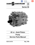
Series 90
Axial Piston
Pumps and Motors
Repair Manual
CONTENTS
saue
Axial Piston Pumps and Motors
Series 90
General Description
Series 90 Variable Displacement Pumps are cradle
swashplate design units, incorporating parallel axial
pistons with slippers.
Series 90 Fixed and Variable Displacement Motors
are swashplate design units, incorporating parallel
axial pistons with slippers.
These pumps are designed to be combined with
other products in closed circuit systems to transfer
and control hydraulic power.
These motors are primarily designed to be combined
with other products in closed circuit systems to transfer and control hydraulic power.
The pump output flow rate is proportional to the
pump's input speed and is determined by the swashplate angle, which may be infinitely varied between
zero and maximum displacement.
The output speed is proportional to the flow rate of the
hydraulic fluid through the motor (and the motor
displacement, for variable motors). Output torque is
proportional to the difference in the pressure levels in
the high and low sides of the fluid circuit.
The pump's flow direction is reversed by tilting the
swashplate to the opposite side of the zero displacement position.
A compact, responsive, closed loop servo system,
with a choice of manual, hydraulic, or electrical input,
controls the swashplate angle. An automotive drive
control is also available.
The motor's direction of rotation depends on the
direction of fluid flow through the motor.
Variable Displacement Motors are available with 2position electric solenoid or hydraluic displacement
control, and utilize internally supplied servo pressure. Variable motors normally start at maximum
displacement. Activation of the motor control results
in the motor shifting to minimum displacement.
● The Series 90 — Advanced Technology Today
● The Most Technically Advanced Hydraulic Units in the Industry
● 8 Sizes of Variable Displacement Pumps
● 6 Sizes of Fixed Displacement Motors
● Complete Family of Control Systems
● Proven Reliability and Performance
● Optimum Product Configurations
● Compact, Lightweight
Copyright 1987, 1991, 1992, Sauer-Sundstrand Company
All rights reserved. Contents subject to change. Printed in U.S.A. 0792 H
CONTENTS
saue
Axial Piston Pumps and Motors
Series 90
Contents
Introduction ................................................................................................................................................. 0 - 2
Safety Precautions .................................................................................................................................... 20 - 1
Tool Information ........................................................................................................................................ 20 - 2
Exploded View of the Variable Displacement Pump ................................................................................. 40 - 1
Exploded View of the Fixed Displacement Motor .................................................................................... 40 - 13
Exploded View of the Variable Displacement Motor ............................................................................... 40 - 17
Major Repair - Variable Pump ................................................................................................................... 61 - 1
General .............................................................................................................................................. 61 - 1
Disassembly Procedures for Variable Displacement Pump ............................................................... 61 - 2
Reconditioning and Replacement of Parts ......................................................................................... 61 - 6
Assembly Procedures for Variable Displacement Pump ................................................................. 61 - 12
Major Repair - Fixed Motor ....................................................................................................................... 62 - 1
General .............................................................................................................................................. 62 - 1
Disassembly Procedures for Fixed Displacement Motor ................................................................... 62 - 2
Reconditioning and Replacement of Parts ......................................................................................... 62 - 4
Assembly Procedures for Fixed Displacement Motor ........................................................................ 62 - 6
Major Repair - Variable Motor ................................................................................................................... 63 - 1
General .............................................................................................................................................. 63 - 1
0 -1
CONTENTS
saue
Axial Piston Pumps and Motors
Series 90
Introduction
This manual provides “Major Repair” procedures for
the Series 90 variable displacement pumps and fixed
and variable displacement motors.
Minor Repairs are those repairs which can be
performed without removing the end cap or side
cover. These repairs can be performed by any
customer without affecting the unit warranty. These
repairs are described in the “Series 90 — Service
Manual,” Bulletin BLN-9947.
Major Repairs are those repairs which require the
removal of the end cap or side cover. These repairs
are to be performed only by Sauer-Sundstrand Authorized Service Centers and/or original equipment
manufacturers who have been adequately trained by
Sauer-Sundstrand to perform these repairs. Performing major repairs on the Series 90 products may
affect the unit warranty status, thus the factory should
be consulted prior to undertaking such repairs.
90000015
Series 90 Variable Displacement Pump
0-2
These repair procedures, when used in conjunction
with the Series 90 Service manual, Bulletin BLN9947, provide complete service and repair information for the Series 90 products.
For Technical Information on Series 90 pumps and
motors, refer to BLN-10029 and BLN-10030.
For Fluid Quality Requirements, refer to bulletin BLN9887, or Publication SDF (Id. No. 697581).
Sauer-Sundstrand provides a complete repair service for its products. Contact any Sauer-Sundstrand
Authorized Service Center for details. Sauer-Sundstrand Authorized Service Center locations are listed
in BLN-2-40527, or Publication SAW (Id. No. 698266).
90000016
Series 90 Fixed Displacement Motor
CONTENTS
saue
Axial Piston Pumps and Motors
Series 90
Safety Precautions
● When Series 90 units are used in vehicular
hydrostatic drive systems, the loss of hydrostatic drive line power in any mode of operation may cause a loss of hydrostatic braking
capacity. A braking system, redundant to
the hydrostatic transmission must, therefore, be provided which is adequate to stop
and/or hold the system should the condition develop.
● Certain service procedures may require the
vehicle/machine to be disabled (wheels
raised off the ground, work function disconnected, etc.) while performing them in order
to prevent injury to the technician and bystanders.
● Use caution when dealing with hydraulic
fluid under pressure. Escaping hydraulic
fluid under pressure can have sufficient
force to penetrate your skin causing serious injury. This fluid may also be hot
enough to burn. Serious infection or reactions can develop if proper medical treatment is not administered immediately.
● Some cleaning solvents are flammable. To
avoid possible fire, do not use cleaning
solvents in an area where a source of ignition may be present.
● Always test Series 90 units prior to reinstalling in order to verify correct function of
controls and other systems.
20 - 1
CONTENTS
saue
Axial Piston Pumps and Motors
Series 90
Tool Information
90000129
90000170
Fig. 20-1 - Removing Fig. 20-2 - Removing
Journal Bearing (PV) Journal Bearing (MF/
MV)
“B”
0.10 (2.54)
“A” DIA
5° (±1°)
0.02 (0.51) R
90000134
Fig. 20-3 - Sizing
Journal Bearing in
End Cap (PV)
90000145
Fig. 20-5 - Install
Assembly Tool (PV)
20 - 2
90000188
Fig. 20-4 - Journal
Bearing Sizing Arbor
Dimensions
90000215
Fig. 20-6 - Install Flat
Washer on
Assembly Tool
Certain tools are helpful in disassembling and assembling Series 90 pumps and motors which are not
normally included in the typical mechanic’s set of
tools. These include:
An internal puller for removing the shaft journal bearing from the end cap. (Example: Snap-On Tools
Puller Set CG45)
Sizing arbors for the end cap shaft journal bearing
(Sauer-Sundstrand part number 9510667-XXXX).
CAUTION
The pump or motor shaft must NOT be used to
size the bearing. Inadequate clearance between
the shaft and bearing will result in inadequate
lubrication and shortened bearing life.
Dimensions for the sizing arbors are shown in the
accompanying figure and table. The arbors are made
of AISI 4140 steel. A 4 to 8 RMS microfinish and a
hardness of 50 to 57 Rc is required on Diameter “A.”
Diameter “A”
Frame
(±0.0001 in. or
Dimension “B”
Size
±0.00254 mm)
Minimum
030
25.300 mm
22.0 mm
042
28.010 mm
30.5 mm
055
1.1818 in.
1.00 in.
075
1.3785 in.
1.20 in.
100
1.5000 in.
1.27 in.
130
44.984 mm
40.5 mm
A tool to aid in holding and installing the assembled
cylinder block and swashplate into the variable pump
housing may be made from a positive lock, quick
release pin and a large flat washer (1 inch inside
diameter with clearance flats ground on the outside
diameter). The 1 inch diameter pin is defined by
military specification MS 17985 C 16 60, and is
available from a number of sources. These include:
QRP, Incorporated
Reach Road & North Drive, PO Box T3572
Williamsport, PA 17701-0572
Telephone: (717) 322-8060
Carr Lane Manufacturing Co.
4200 Carr Lane Court, PO Box 13149
St. Louis, MO 63119
Telephone: (314) 647-6200
Lockwell Products
Division of The Hartwell Corporation
900- T South Richfield Road
Placentia, CA 92670
Telephone: (714) 579-4425
CONTENTS
saue
Axial Piston Pumps and Motors
Series 90
Exploded View of the Variable Displacement Pump
The following information is for general parts identification ONLY. Refer to the applicable Service Parts
List when ordering service parts.
K90
B70
G532
G536
B83
OR
B83
K10
K50
K70
G542
G546
B82
L35
(Early Production
075 Frame Size)
K018
THRU
K042
K80
L60
L70
(B80)
L40
(B90)
L30
P2B_
(B70)
P30
(L70)
(L40)
P06
P13
B90
L50
P30
(K018
THRU
K042)
B71
P2A_
P06
P13
G512
G516
G502
G506
G531
G538
G501
G508
G511
G518
G172
G176
G522
G526
B80
(G502
G506) (G502
G506)
G541
G548
(G63)
G63
(CODE 61 OPTION)
(G64)
OR
G64
(CODE 61 OPTION)
BOTH SIDES
G63
(CODE 61 OPTION)
G521
G528
(G501
G508) (G501
(G63)
G64
(CODE 61 OPTION)
(G64)
G508)
saue
Ames, Iowa, U.S.A.
Model Code
Model
Number
Serial
Number
90L055
EA
1 N
6 S 3 C6 C 03
HNN 35 35 24
Model No.
saue
Ames, Iowa, U.S.A.
Model Code
Neumünster, Germany
Typ
Model
Code
Ident Nr
94 – 2029
A – 88 – 26 – 67890
Serial No.
Fabr Nr
MADE IN U.S.A.
Place of Manufacture
Name Plate (U.S.A. Production)
Model
Number
Serial
Number
Neumünster, Germany
Typ
90L055
EA
1 N
6 S 3 C6 C 03
HNN 35 35 24
Model No.
Model
Code
Ident Nr
687459
N – 88 – 26 – 67890
Serial No.
Fabr Nr
MADE IN GERMANY
Place of Manufacture
Name Plate (German Production)
40 - 1
CONTENTS
saue
Axial Piston Pumps and Motors
Series 90
Exploded View of the Variable Displacement Pump (Continued)
M9ME
M0MA M0ME
M0MB M0MF
M0MC M0MG
M0MD M0M9
M74M
M78M
M76M
M0CA
OR
M90D
M1DC
M1DD
MODC
MODD
M1CA
M11C
M90C
M87C
M92M
M11D
M97M
M95M
M96M
T001
THRU
T009,
T022
T050
M75M
M98M
S40
M90M
M1MA M880
M1MB
M1MC
M1MD
M1ME
M1MF
M1MG
T201
THRU
T209,
T222
T250
T301
THRU
T309,
T322
T350
T401
THRU
T409,
T422
T450
M72M
M71M
M7MA
M7MB
M7MC
M7MD
M7ME
M7MF
M7MG
M1HA, M1HC
M1HF, M1HG
M1HH, M1HJ
M1HK, M1HL
M1HM, M1HN
M11H
M90H
M880
M87H
OR
M91E
M90E
M1EA M880
M1EF
M1EP
M860
M840
M840
REF
M830
M810
M840
REF
M820
EARLY PRODUCTION
130CC PUMPS ONLY
OR
M0HA, M0HC
M0HF, M0HG
M0HH, M0HJ
M0HK, M0HL
M0HM, M0HN
M98E
M95E
M97E
M96E
M87E
OR
M850
M9EA
M9EP
M11E
M87M M11M
M870
40 - 2
M0EA
M0EF
M0EP
M77M
CONTENTS
saue
Axial Piston Pumps and Motors
Series 90
Exploded View of the Variable Displacement Pump (Continued)
W741
W701
W740
W74A
W754
W755
W756
W751
A
W752
W122
W121
W701
W10A
W004
W702
W753 W757
W756
W755
W754
W70A
W304
W547
W005
W542
W004
W541
W005
W543
W544
W548
W545
W546
W551
W552
W521
W554
W522
W550
W523
W553
W524
W525
W501
W502
W503
W504
W505
W21A
THRU
T660 THRU T665
W002 W26A
T560 THRU T565
M78A
W006
W302
A
M90A
W414
W011
W402
W013
W012
W555
W556
W557
W559
M11A
W014
W558
W560
W561
W563
W562
M87A
W008
W010
W009
M92A
M1AC
W001
W41A
W001
M77A
W003
W015
W30A
W007
W750
W526
W528
W529
W527
W506
40 - 3
CONTENTS
saue
Axial Piston Pumps and Motors
Series 90
Exploded View of the Variable Displacement Pump (Continued)
N40P
N40L
N00M
N00S
N35M
REF
N30R
N10M
N35M
N20M
N15M
N31R
N00R
N10R
N20R
N15R
N25R
N35R
N35S
N10S
N25M
OR
OR
H50L
H50
H40
H05
OR
H30
H60
H50
H40
H30
OR H05
(H30)
J80N
H40
H05
H60
H50
OR
H60
H50
H90L
J40N
J15N
H70
J15_, J15L, OR J15R
J10_
J30
J30
H80
J70_
OR
H70
J50_
J80_
J60_
J90_
H80
J00_, JL0_, OR JR0_
J92_
J95_
40 - 4
CONTENTS
saue
Axial Piston Pumps and Motors
Series 90
Exploded View of the Variable Displacement Pump (Continued)
C20
C30
C50
C40
C65
C70
S07
B10
C05
C13
B50 REF
C14
C80
C15
C16
M14E
M14H
M14M
D65
B20 REF
D60
B20
F20
D85
D95
B50
B30
D80
D50
40 - 5
CONTENTS
saue
Axial Piston Pumps and Motors
Series 90
Exploded View of the Variable Displacement Pump (Continued)
L20
S03
L10
F603
S01
L1C3
L1C6
L1C7
L1F1
L1S1
L1S3
L1S4
F344
F354
F603
F40
F50
L10
OR
F40
F50
L1T1
L1T2
L1TF (SPECIAL)
L8T1
L8T2
L9T1
L9T2
L9TF
OR
L8K1
L8K2
L8K3
L1K1
L1K2
L1K3
S10
OR
F12 F11
REF REF
E30 REF
E80
REF
E24
REF
E82
REF
E22
REF
E81
E30
F11
F12
F50
F40
F344
E20
E22
F50
F40
F354
F60
E82
E80
E50
E24
F60
S02
E10
E40
E40
REF
E61
E60
F 106
F 306
F 136
F 146
F 726
F 736
F 746
F 776
F 826
F 786
F 806
F 796
F 706
F 716
40 - 6
F 606
F 816
S04
CONTENTS
saue
Axial Piston Pumps and Motors
Series 90
Exploded View of the Variable Displacement Pump (Continued)
P807
P802
P80
P80
P70
P70
ENDCAP GASKET FACE
OF ITEM G04X (TYPICAL)
WITH PRESSURE LIMITERS
LEFT HAND ROTATION
ENDCAP GASKET FACE
OF ITEM G04X (TYPICAL)
WITH PRESSURE LIMITERS
RIGHT HAND ROTATION
P707
P702
ENDCAP GASKET FACE
OF ITEM G04X (TYPICAL)
WITHOUT PRESSURE LIMITERS
LEFT/RIGHT HAND ROTATION
G94
G93
G952 G95
G956
G302
G306
G902
G906
G078
G068
G20
G182 G088
G186
P70
G40
G94
G93
G952 G95
G956
G301
G308
P80
GASKET FACE OF ITEM G068
WITH PRESSURE LIMITERS
RIGHT HAND ROTATION
OR
NOTES:
G20
G042
G046
P70
ITEMS G042 & G046 DO NOT
INCLUDE ITEMS G93, G94, G95,
G902, G906, G952, & G956.
G40
G041
G048
ITEMS G041 & G048 DO NOT
INCLUDE ITEMS G93, G94, G95,
G951, & G958
P80
GASKET FACE OF ITEM G068
WITH PRESSURE LIMITERS
LEFT HAND ROTATION
40 - 7
CONTENTS
saue
Axial Piston Pumps and Motors
Series 90
Exploded View of the Variable Displacement Pump (Continued)
Item
Description
Qty
B10
B20
B30
B50
B70
B80
B90
C05
C13
C14
C15
C16
C20
C30
C40
C50
C65
C70
C80
D50
D80
D85
D95
E10
E20
E22
E24
E30
E40
E50
E60
E61
E70
E80
F11
F12
F20
VARIABLE HOUSING
PIN
BEARING
PIN
PLUG
PLUG
CONTROL FILTER SCREEN
CYLINDER BLOCK ASSY
SPRING SEAT
CYLINDER BLOCK SPRING
SPRING RETAINER
RETAINING RING
PISTON
SLIPPER GUIDE
SLIPPER GUIDE BEARING
SPACER
WASHER
SCREW
VALVE PLATE
SWASHPLATE ASSY
CAGE LOCATOR LINK
PIN
SPRING
SIDE COVER
LEVELER
SPRING SEAT
SHIM
GUIDE POST
NUT
O RING
SCREW
WASHER - FLAT
PLUG
SPRING
O RING
PISTON RING
SLIDER BLOCK
1
1
1
1
1
1
2
2
2
2
1
6
6
1
2
2
2
1
F003
F004
F40
F50
F60
F344
F354
SERVO SLEEVE KIT - NO LIMITER
SERVO SLEEVE KIT - ADJUSTABLE
O RING
O RING
SCREW
SCREW
NUT
2
2
2
2
6
2
2
F106
F136
F146
F306
F606
F706
F716
F726
SERVO PISTON (FBA)
NEUTRAL SPRING CANNISTER (FBA)
SCREW
SERVO SLEEVE (FBA)
SCREW
O-RING
NEUTRAL SPRING COVER (FBA)
SCREW
1
1
1
1
3
1
1
1
40 - 8
1
2
1
2
2
1
3
1
1
1
1
1
9
1
1
4
4
4
Item
Description
Qty
F736
F746
F776
F786
F796
F806
F816
F826
SPRING GUIDE (INNER)
SPRING
SPRING GUIDE (OUTER)
RETAINING RING
NUT
NUT - LOCK
NUT - SEAL LOCK
WASHER - FLAT
1
1
1
1
1
1
1
4
G048
G046
G20
G40
G61
G62
G63
G64
G068
G078
G088
G93
G94
G95
G306
G308
G506
G508
G526
G546
G906
G956
G958
END CAP - TWIN PORTS
END CAP - AXIAL PORTS
JOURNAL BEARING
BUSHING
PORT SHIPPING COVER GASKET
PORT SHIPPING COVER
SPLIT CLAMP
SCREW - SHIPPING COVER
VALVE HOUSING ASSY
SCREW
GASKET
SPACER
LIFTING BRACKET
WASHER
END CAP GASKET
END CAP GASKET
PLUG
PLUG
PLUG
PLUG
SCREW
SCREW
SCREW
1
1
1
1
2
2
4
4
1
4
1
1
1
1
1
1
3
3
1
1
1
1
1
H05B-H
H05L
H30
H40
H50
H60
H70
H80
H90
H90L
KIT - CHARGE PUMP
SPACER (NO CHARGE PUMP)
PORT PLATE
PIN
CHARGE PUMP SHAFT
KEY
RETAINING PLATE
SCREW
PLASTIC PLUG
PLUG
1
1
2
1
1
1
1
6
1
1
J00A
J00B
J00C
J00D
J00T
J00V
J00N
J10A-V
J15
J15N
AUX. MTG. ‘A’ FLANGE
AUX. MTG. ‘B’ FLANGE
AUX. MTG. ‘C’ FLANGE
AUX. MTG. ‘D’ FLANGE
AUX. MTG. ‘A’ FLANGE (11T)
AUX. MTG. ‘B-B FLANGE
AUX. MTG. FLANGE - NONE
COUPLING
CHARGE PUMP COVER ASSY
CHARGE PUMP COVER ASSY
1
1
1
1
1
1
1
1
1
1
CONTENTS
saue
Axial Piston Pumps and Motors
Series 90
Exploded View of the Variable Displacement Pump (Continued)
Item
Description
Qty
Item
1
1
1
1
1
1
1
4
4
4
1
1
2/4
M90C
M14
SCREW
FEEDBACK LINK
6
1
M0DC
M0DD
M1DC
M1DD
M80
M87D
M90D
CONTROL KIT 3 POS F-N-R 12V
CONTROL KIT 3 POS F-N-R 24V
CONTROL 3 POS F-N-R 12V
CONTROL 3 POS F-N-R 24V
CONTROL GASKET
WASHER, SEAL (042)
SCREW
1
1
1
1
1
1
6
M0EA
M0EP
M1EA
M1EP
M9EA
M9EA
M80
M87E
M90E
M91E
M95E
M96E
M97E
M98E
M14
EDC KIT W/MS CONNECTOR
EDC KIT W/PACKARD CONNECTOR
EDC W/MS CONNECTOR
EDC W/PACKARD CONNECTOR
PCP TYPE 3 OIL FILLED (MS)
PCP TYPE 3 OIL FILLED (PACKARD)
CONTROL GASKET
WASHER, SEAL (042)
SCREW
PLASTIC CAP (MS)
O RING
O RING
O RING
SCREW
FEEDBACK LINK
1
1
1
1
1
1
1
1
6
1
2
1
1
4
1
M0HA
M0HC
M1HA
M1HC
M80
M90H
M14
HDC KIT
HDC KIT
HDC
HDC
CONTROL GASKET
SCREW
FEEDBACK LINK
1
1
1
1
1
6
1
M0MA
M7M
M71M
M72M
M80
M90M
M14
MDC W/O NEUTRAL START SWITCH
CONTROL HANDLE
WASHER
NUT
CONTROL GASKET
SCREW
FEEDBACK LINK
1
1
1
1
1
6
1
M0MB
M7M
M71M
M72M
M80
M90M
S40
M14
MDC W/NEUTRAL START SWITCH
CONTROL HANDLE
WASHER
NUT
CONTROL GASKET
SCREW
NEUTRAL START SWITCH KIT
FEEDBACK LINK
1
1
1
1
1
6
1
1
M0MC
M7M
MDC W/SOL. VALVE
CONTROL HANDLE
1
1
J30
J40A-V
J50A-V
J60A/T
J60B/V
J60C
J60D
J70A-V
J80A-V
J80N
J90A-V
J92A-V
J95A-V
BUSHING
O RING
O RING
FLANGE ADAPTOR
FLANGE ADAPTOR
FLANGE ADAPTOR
FLANGE ADAPTOR
WASHER
SCREW
SCREW
O RING
COVER PLATE
SCREW
K000
K10
K50
K70
K80
K90
ADJ. CHARGE RELIEF KIT
PLUG ASSY
O RING
SPRING
POPPET
NUT
1
1
1
1
1
1
L10
L20
L35
L40
L50
L70
ROLLER BEARING
RETAINING RING
SEAL CARRIER
LIP SEAL
O RING
SCREW
1
1
1
1
1
3
L1C3
L1C6
L1C7
L1C8
L1F1
L1K1
L1K2
L1K3
L1S1
L1T1
L1T2
L1T3
L8
L9
SHAFT - PV, SPLINED
SHAFT - PV, SPLINED
SHAFT - PV, SPLINED
SHAFT - PV, SPLINED
SHAFT - PV, SPLINED
SHAFT - PV, STRAIGHT KEY
SHAFT - PV, STRAIGHT KEY
SHAFT - PV, STRAIGHT KEY
SHAFT - PV, SPLINED
SHAFT PV, TAPERED
SHAFT PV, TAPERED
SHAFT PV, TAPERED
KEY
SLOTTED NUT
1
1
1
1
1
1
1
1
1
1
1
1
1
1
M0AC
M77A
M78A
M90A
M92A
M98A
ADAPTER PLATE - FBA CONTROL
ADAPTER PLATE - FBA
SCREW
SCREW
SCREW
SCREW
1
1
6
6
2
1
M0CA
M1C
M80
M87C
CONTROL - COVER PLATE KIT
COVER PLATE
CONTROL GASKET
WASHER, SEAL (042)
1
1
1
1
Description
Qty
40 - 9
CONTENTS
saue
Axial Piston Pumps and Motors
Series 90
Exploded View of the Variable Displacement Pump (Continued)
Item
Description
Qty
Item
P13
P30
P70
P702
P80
P802
O RING
PLASTIC PLUG
CHECK VALVE
PLUG
SPECIAL PLUG
SPECIAL PLUG
2
2
2
1
2
3
S10
F11
F12
SERVO PISTON KIT
O RING
PISTON RING
1
2
2
T001-9
T201
T301
T401
T560-5
T660-5
CONTROL ORIFICE KIT
ORIFICED CHECK VALVE
SPRING
SPRING RETAINER
CONTROL ORIFICE (FBA)
CONTROL ORIFICE (FBA)
1
1
1
1
1
1
S07
C20
C80
S30
C70
E40
E50
E60
F11
F12
F40
F50
G088
G306
G308
J40A
J50A
J90A
J90B
J90C
K50
L40
L50
M77M
M80
M95E
M96E
M97E
N15
P6
P13
CYL. BLOCK KIT W/ PISTONS
PISTON
PUMP VALVE PLATE
OVERHAUL SEAL KIT
SCREW
NUT
O RING
SCREW
O RING
PISTON RING
O RING
O RING
GASKET
END CAP GASKET - AXIAL PORTS
END CAP GASKET - TWIN PORTS
O RING
O RING
O RING
O RING
O RING
O RING
LIP SEAL
O RING
MANIFOLD GASKET
CONTROL GASKET
O RING
O RING
O RING
O RING
O RING
O RING
1
9
1
1
4
2
1
6
2
2
2
2
1
1
1
1
1
1
1
1
1
1
1
1
1
2
1
1
1
2
2
M71M
M72M
M74M
M75M
M77M
M78M
M80
M90M
M14
WASHER
NUT
SOLENOID VALVE
CONTROL MANIFOLD
MANIFOLD GASKET
SCREW
CONTROL GASKET
SCREW
FEEDBACK LINK
1
1
1
1
1
2
1
6
1
M0MD
M7M
M71M
M72M
M75M
M76M
M77M
M78M
M80
M90M
S40
M14
MDC W/SOL. VALVE, NSS
CONTROL HANDLE
WASHER
NUT
CONTROL MANIFOLD
SOLENOID VALVE
MANIFOLD GASKET
SCREW
CONTROL GASKET
SCREW
NEUTRAL START SWITCH KIT
FEEDBACK LINK
1
1
1
1
1
1
1
2
1
6
1
1
M810
M820
M830
M840
M850
M860
M870
ADAPTER PLATE - CONTROL (130 CC)
O-RING (130 CC)
O-RING (130 CC)
O-RING (130 CC)
PLUG (130 CC)
SCREW (130 CC)
PLUG (130 CC)
1
1
1
2
1
6
1
N00M
N10M
N15M
N20M
N25M
N30M
N40L
N40P
FILTRATION MANIFOLD KIT (INT)
MANIFOLD
O RING
NUT
TUBE
PLUG
FILTER
FILTER
1
1
2
1
1
2
1
1
N00R
N10R
N15R
N20R
N25R
N30R
N00R
FILTRATION MANIFOLD KIT (RMT)
MANIFOLD
O RING
NUT
TUBE
PLASTIC PLUG
PLUG
1
1
1
1
1
2
1
N10S
N30S
REDUCER FITTING (SUCTION FLT)
PLUG
1
1
P2A
P2B
P6
MULTI-FUNCTION VALVE ASSY
MULTI-FUNCTION VALVE ASSY
O RING
1
1
2
40 - 10
Description
Qty
CONTENTS
saue
Axial Piston Pumps and Motors
Series 90
Exploded View of the Variable Displacement Pump (Continued)
Item
W001
W002
W003
W004
W005
W006
W007
W008
W009
W010
W011
W012
W013
W014
W015
W10A
W121
W122
W21-26A
W30A
W302
W304
W41A
W402
W414
W501
W502
W503
W504
W505
W506
W521
W522
W523
W524
W525
W526
W527
W528
W529
W541
W542
W543
W544
W545
W546
W547
W548
W550
W551
Description
VALVE BLOCK (FBA)
PLUG
PLUG
O-RING
O-RING
STARTING THROTTLE (FBA)
NUT - SEAL LOCK
PLUG - EXPANDER
PLUG ASSY
NUT
O RING
POPPET
SPRING
SEAT
ORIFICE
THERMOVALVE (FBA)
PLATE (FBA)
SCREW
MAIN ORIFICE (FBA)
PRESSURE RELIEF VALVE (FBA)
O-RING
NUT - SEAL LOCK
THROTTLE OR PRESS VALVE (FBA)
O-RING
NUT - SEAL LOCK
SCREW (LESS INCHING)
PLATE (LESS INCHING)
O-RING (LESS INCHING)
PLUG (LESS INCHING)
SPOOL (LESS INCHING)
PLUG (LESS INCHING)
SCREW (MECH INCHING)
PLATE (MECH INCHING)
O-RING (MECH INCHING)
PLUG (MECH INCHING)
SPOOL (MECH INCHING)
WASHER - FLAT (MECH INCHING)
O-RING (MECH INCHING)
O-RING (MECH INCHING)
PLUG (MECH INCHING)
CYLINDER ASSY (HYD INCHING)
SCREW (HYD INCHING)
PISTON CYLINDER(HYD INCHING)
PISTON (HYD INCHING)
SEAL - PISTON (HYD INCHING)
SEAL RETAINER (HYD INCHING)
PLUG (HYD INCHING)
BLEED SCREW (HYD INCHING)
PIN (HYD INCHING)
O-RING (HYD INCHING)
Qty
Item
1
1
1
1
1
1
1
4
1
1
1
1
1
1
1
1
1
4
1
1
1
W552
W553
W554
W555
W556
W557
W558
W559
W560
W561
W562
W563
W70A
W701
W702
W74A
W740
W701
W741
W750
W751
W752
W753
W754
W755
W756
W757
1
1
1
2
1
1
1
1
1
2
1
1
1
1
1
1
1
1
1
2
1
1
1
1
1
1
1
1
Description
Qty
PLUG (HYD INCHING)
1
O-RING (HYD INCHING)
1
O-RING (HYD INCHING)
1
SPOOL (HYD INCHING)
1
SPRING SEAT - INNER (HYD INCHING) 1
SPRING (HYD INCHING)
1
SPRING WASHERS (HYD INCHING)
SPRING SEAT - OUTER (HYD INCHING) 1
O-RING (HYD INCHING)
1
PLUG - THREADED (HYD INCHING)
1
NUT - SEAL LOCK (HYD INCHING)
1
SCREW - ADJUSTING (HYD INCHING) 1
3 POS / 4 WAY VALVE (FBA)
1
FNR VALVE (ELECTRICAL)
1
SCREW
4
3 POS / 4 WAY VALVE W/INCH (FBA)
1
FNR VALVE
1
FNR VALVE (ELECTRICAL)
1
SCREW
4
INCH VALVE (ROTARY)
1
VALVE BLOCK
1
PLUG
1
VALVE SPOOL
1
RING - RETAINING
2
RETAINER
2
O-RING
2
GASKET
1
40 - 11
CONTENTS
saue
Axial Piston Pumps and Motors
Series 90
Exploded View of the Fixed Displacement Motor
The following information is for general parts identification ONLY. Refer to the applicable Service Parts
List when ordering service parts.
H68W
L35
(Early Production
075 Frame Size)
H60W
H62W
H64W
(L70)
(L40)
H66W
L60
H60N
L40
(B80)
(H50N)
L70
L30
(G50)
(H50W)
(H30W)
L50
(H40W)
(H20W)
G50
G70
H10N
(B80)
H50N
H20W
(G63)
H10W
B80
G63
(CODE 61 OPTION)
H40W
H30W
H50W
(G64)
G64
(CODE 61 OPTION)
OR
B83
B83
B80
G63
(CODE 61 OPTION)
(G63)
G64
(CODE 61 OPTION)
saue
Ames, Iowa, U.S.A.
Model Code
Mode
Number
Serial
Number
Model No.
Ames, Iowa, U.S.A.
Model Code
(B83)
Ident Nr
Serial No.
Fabr Nr
MADE IN U.S.A.
Place of Manufacture
Neumünster, Germany
Typ
90M055
NC
0 N
8 N 0 C6 W 00
NNN 00 00 24
Model
Code
94 – 2029
A – 91 – 26 – 67890
Name Plate (U.S.A. Production)
(B83)
saue
Neumünster, Germany
Typ
90M055
NC
0 N
8 N 0 C6 W 00
NNN 00 00 24
(G64)
Model
Number
Serial
Number
Model No.
Model
Code
Ident Nr
312918
N – 91 – 26 – 67890
Serial No.
Fabr Nr
MADE IN GERMANY
Place of Manufacture
Name Plate (German Production)
40 - 13
CONTENTS
saue
Axial Piston Pumps and Motors
Series 90
Exploded View of the Fixed Displacement Motor (Continued)
D50
C20
L20
L10
C30
L1C6, L1C7
L1F1, L1F2
L1S1, L1S3
C40
S07
C45
L10
L8T1
L8T2
L1T1
L1T2
C05
L9T1
L9T2
OR
C13
OR
C14
OR
C15
C16
L1K1
L1K2
L1K3
C50
G25
REF
C80
B10
G25
OR
G30
G20
G20
G95
B10
G043
G047
OR
G96
G90
G041
G048
40 - 14
L8K1
L8K2
L8K3
CONTENTS
saue
Axial Piston Pumps and Motors
Series 90
Exploded View of the Fixed Displacement Motor (Continued)
Item
Description
Qty
B10
B80
C05
C13
C14
C15
C16
C20
C30
C40
C45
C50
C80
D50
G25
G30
G50
G70
G90
G95
G96
FIXED HOUSING
PLUG
CYLINDER BLOCK ASSY
SPRING SEAT
SPRING
SPRING RETAINER
RETAINING RING
SEE ‘W’ GROUP FOR PISTONS
SLIPPER GUIDE
SLIPPER GUIDE RETAINER
SLIPPER GUIDE RETAINER SHIM
HOLD DOWN TUBE
VALVE PLATE
THRUST PLATE
PIN
END CAP GASKET
PLUG
PLUG
SCREW
SCREW
SCREW
1
2
1
1
1
1
1
1
1
1
1
1
1
2
1
2
1
4
2
1
G047
G048
G20
G61
G62
G63
G64
END CAP - AXIAL PORTS
END CAP - TWIN PORTS
JOURNAL BEARING
PORT SHIPPING COVER GASKET
PORT SHIPPING COVER
SPLIT CLAMP
SCREW - SHIPPING COVER
1
1
1
2
2
4
4
H10N
H50N
LOOP FLUSHING SPOOL - DEFEAT
PLUG
1
2
H10W
H20W
H30W
H40W
H50W
SHUTTLE VALVE SPOOL
SPECIAL WASHER
SPRING
O RING
SPECIAL PLUG
1
2
2
2
2
K000
PLUG
1
K10
K50
K610
K70
K80
PLUG ASSY
O RING
SHIM
SPRING
POPPET
Item
Description
Qty
L10
L20
L35
L40
L50
L70
ROLLER BEARING
RETAINING RING
SEAL CARRIER
LIP SEAL
O RING
METRIC SCREW
1
1
1
1
1
3
L1C6
L1C7
L1K2
L8
L1S1
L1T2
L8
L9
SHAFT - SPLINED
SHAFT - SPLINED
SHAFT - STRAIGHT KEY
KEY
SHAFT - SPLINED
SHAFT - TAPERED
KEY
SLOTTED NUT
1
1
1
1
1
1
1
1
S07
C20
CYLINDER BLOCK KIT W/PISTONS
PISTON
1
9
S30
G30
H40W
K50
L40
L50
OVERHAUL REPAIR KIT
END CAP GASKET
O RING
O RING
LIP SEAL
O RING
1
1
2
1
1
1
1
1
A/R
1
1
40 - 15
CONTENTS
saue
Axial Piston Pumps and Motors
Series 90
Exploded View of the Variable Displacement Motor • 055 and 075
The following information is for general parts identification ONLY. Refer to the applicable Service Parts
List when ordering service parts.
Y100
Y101
Y102
Y40
E15
E35
E26
Y50
Y60
(Y50)
L35
(Early Production
075 Frame Size)
(L70)
L60
(L40)
L70
L30
L40
B83
(B74)
B80
B83
L50
B76
H68W
T100
T101
T30
T40
T50
T60
(T50)
(B74)
H60W
H62W
M1PT
Y71
Y80
H64W
B74
Y72
Y70
H66W
M1NA, M1NB
M1NC, M1ND
H60N
P700
P702
G50
(H50N)
(P400)
(P401)
(P402)
(P403)
(B80)
(G50)
E25
(B74)
E35
(H50W)
(H40W)
(H30W)
(H20W)
(P400)
(P401)
(P402)
(P403)
E15
H10N
G70
P601
P603
P600
P602
H50N
H10W
H20W
(G63)
H30W
H40W
H50W
P800
(G64)
G63
(CODE 61 OPTION)
G64
(CODE 61 OPTION)
saue
Ames, Iowa, U.S.A.
Model Code
Neumünster, Germany
Typ
90S055
NB
2 0
8 N 4 S1 W 01
NNN 01 00 24
Model No.
Model Number
Serial Number
Model Code
Ident Nr
94 – 4002
A – 91 – 26 – 67890
Serial No.
Fabr Nr
MADE IN U.S.A.
Place of Manufacture
Name Plate (U.S.A. Production)
40 - 17
CONTENTS
saue
Axial Piston Pumps and Motors
Series 90
Exploded View of the Variable Displacement Motor • 055 and 075 (Continued)
L10
L20
D10
L1NX or
L1SX
L8TX
C20
D50
C30
S07
P202
P203
C50
C40
C65
C70
P35
L1TX
P302
P303
(B51)
C05
L9TX
OR
(B20)
P35
P200
P201
(B30)
C13
D30
D20
B51
C14
C15
C16
B20
B30
F45
L80
F15
F25
F65
F49
(B50)
L90
P102
P103
C80
B50
OR
G80
G82
G86
G84
P100
P101
(F49)
(F45)
F35
(F25)
G30
(F15)
G20
G95
G041
G048
G96
G90
40 - 18
OR
P300
P301
CONTENTS
saue
Axial Piston Pumps and Motors
Series 90
Exploded View of the Variable Displacement Motor • 055 and 075 (Continued)
Item
Description
Qty
Item
Description
Qty
B20
B30
B50
B51
B74
B76
B80
B83
B83
C05
2
3
4
5
C20
C30
C40
C50
C65
C70
C80
D10
D20
D30
D50
E15
E25
E35
F15
F25
F35
F45
F49
F65
G20
G30
PIN
CRADLE BEARING
PIN
PIN
PLUG
PLUG
PLUG
PLUG
SPEED SENSOR
CYLINDER BLOCK ASSEMBLY
SPRING
RETAINER
RING
SEAT
PISTON ASSEMBLY
SLIPPER GUIDE
SLIPPER GUIDE BEARING
SPACER
WASHER
SCREW
VALVE PLATE
HOLD DOWN ARM
O-RING
HOLD DOWN PIN
SWASHPLATE
CAP
SET SCREW
NUT - SEAL LOCK
SPECIAL PLUG
O-RING
SPRING
SERVO PISTON ASSEMBLY
PISTON SEAL RING
SPRING
JOURNAL BEARING
END CAP GASKET
2
2
2
2
4
1
2
1
1
1
1
1
1
2
9
1
2
4
4
4
1
1
1
1
1
1
1
1
2
2
1
2
4
1
1
1
H10W
H20W
H30W
H40W
H50W
H60W
H62W
H64W
H66W
H68W
SHUTTLE VALVE SPOOL
SPRING GUIDE
SPRING
O-RING
SPECIAL PLUG
CHARGE RELIEF VALVE PLUG
O-RING
SPRING
CHARGE RELIEF POPPET
LOCK NUT
1
2
2
2
2
1
1
1
1
1
L1
L2
L8
L9
SHAFT - SPLINED
SHAFT - TAPERED
KEY
SLOTTED NUT
1
1
1
1
L10
L20
L35
L40
L50
RETAINING RING
ROLLER BEARING
SEAL CARRIER
LIP SEAL
O-RING
1
1
1
1
1
L70
L80
L90
SCREW
FRONT COVER GASKET
O-RING
3
1
1
M1
CONTROL VALVE
1
P35
P100
P200
P300
P400
P600
P601
P700
SCREW
VARIABLE MOTOR HOUSING
FRONT COVER
SCREW
PLUG
PLUG
PRESS COMPENSATOR VALVE
SPECIAL PLUG
4
1
1
4
2
1
1
1
G41
G50
G61
G62
G63
G64
END CAP
PLUG
PORT SHIPPING COVER GASKET
PORT SHIPPING COVER
SPLIT FLANGE CLAMP
SHIPPING COVER SCREW
1
2
2
2
4
4
S07
CYLINDER BLOCK KIT W/PISTONS
1
T30
T40
T50
T60
T100
FILTER SCREEN
O-RING
BACK UP RING
O-RING
ORIFICE PLUG
1
1
2
1
1
G70
G80
G82
G84
G86
G90
G95
G96
PLUG
SPRING PIN
BALL
CRUSH RING
ORIFICE
SCREW
SCREW
SCREW
1
1
1
1
1
4
2
1
Y40
Y50
Y60
Y100
O-RING
BACK UP RING
O-RING
ORIFICE PLUG
1
2
1
1
H10N
H50N
H60N
LOOP FLUSHING SPOOL - DEFEAT
PLUG
PLUG
1
2
1
40 - 19
CONTENTS
saue
Axial Piston Pumps and Motors
Series 90
Major Repair - Variable Pump
General
The procedures on the following pages are for the
complete disassembly and reassembly (Major Repair) of the Series 90 Variable Displacement Pump.
Cleanliness is a primary means of assuring satisfactory hydraulic pump life, on either new or repaired
units. Cleaning parts by using a clean solvent wash
and air drying is usually adequate. As with any
precision equipment, all parts must be kept free of
foreign materials and chemicals. Protect all exposed
sealing surfaces and open cavities from damage and
foreign material.
Valve Plate
Piston
During the assembly of the Series 90 variable pump,
all surfaces which have relative motion between two
parts should be coated with a film of clean hydraulic
oil. This will assure that these surfaces will be
lubricated during start-up.
It is recommended that all O-rings and gaskets be
replaced. Lightly lubricate all O-rings with clean
petroleum jelly prior to assembly. All gasket sealing
surfaces must be cleaned prior to installing new
gaskets.
Control Piston
Manual Displacement Control
Charge Pump
Roller Bearing
Input Shaft
Cylinder Block
Cradle Swashplate
90000189
Fig. 61-1 - Cross Section View of Series 90 Variable Displacement Pump
61 - 1
CONTENTS
saue
Axial Piston Pumps and Motors
Series 90
Major Repair - Variable Pump (Continued)
Disassembly Procedures for Variable
Displacement Pump
Prior to performing Major Repairs on the Series 90
Variable Displacement Pump, remove the external
components as described in the “Minor Repair” section of the Series 90 Service Manual. These include
the following:
Auxiliary Mounting Pad (Where Applicable)
Charge Pump
Control
Filter Options
Charge Relief Valve
Multi-Function Valves
Shaft Seal
After removal of these components, place the pump
on a work surface with the shaft up.
Remove the shaft and bearing assembly from the
housing. The bearing outside diameter is a slip fit in
the housing bore.
90000102
Fig. 61-2 - Pump
Positioned on End
Cap
90000103
Fig. 61-3 - Remove
Shaft and Bearing
NOTE: If the shaft and bearing stick in the housing,
lightly tap the end of the shaft with a soft
mallet to free the bearing.
Remove the retaining ring and press the shaft out of
the bearing.
Place the pump on the work surface with the end cap
up.
90000192
Fig. 61-4 - Remove
Bearing from Shaft
90000104
Fig. 61-5 - Pump
Positioned on
Mounting Flange
NOTE: If the pump was equipped with an auxiliary
mounting pad, temporarily reinstall two (2)
of the large screws which fasten the end
cap to the housing. These screws will hold
the end cap against internal spring pressure while the small screws are removed.
Using a 5 mm or 6 mm internal hex wrench or a 10 mm
hex wrench, remove the two (2) or three (3) small
screws which fasten the end cap to the pump housing.
90000193
Fig. 61-6 - Remove
Small End Cap
Screws
61 - 2
90000105
Fig. 61-7 - Remove
Large End Cap
Screws
Using an 8 mm internal hex wrench for 042 pumps, a
19 mm hex wrench for 055 pumps, a 24 mm hex
wrench for 075 and 100 pumps, or a 14 mm internal
hex wrench for 130 pumps, remove the large screws
which fasten the end cap to pump housing.
CONTENTS
saue
Axial Piston Pumps and Motors
Series 90
Major Repair - Variable Pump (Continued)
Remove end cap from housing. The alignment pins
and valve plate will normally remain with the housing.
Remove the end cap gasket. Remove the swashplate leveler spring shims (if installed) from the spring
pockets in the end cap.
Remove three (3) springs from pump: the two (2) long
swashplate leveler (“T-Bar”) springs and the short
swashplate hold down spring.
NOTE: Certain units are equipped with dual swashplate leveler springs (an inner spring “nested”
inside each of the standard springs).
90000107
Fig. 61-8 - Remove
End Cap
90000108
Fig. 61-9 - Remove
Swashplate Springs
Remove the alignment pins and valve plate, noting
direction of arrows on valve plate.
Mark the orientation of the side cover to the housing.
90000109
Fig. 61-10 - Remove
Valve Plate
90000110
Fig. 61-11 - Mark
Side Cover and
Housing
Straighten the locking tabs (used on earlier production units) and remove the six (6) side cover screws
(with flat washers on later production units) using a 10
mm hex wrench for 042 pumps, a 13 mm hex wrench
for 055 thru 100 pumps, or a 17 mm hex wrench for
130 pumps.
Remove side cover and swashplate leveler (“T-Bar”)
assembly from housing.
NOTE: Certain units equipped with dual swashplate
leveler springs have spacer washers on the
leveler spring seats. They may be removed
at this time.
90000111
Fig. 61-12 - Remove
Side Cover Screws
90000112
Fig. 61-13 - Remove
Side Cover
61 - 3
CONTENTS
saue
Axial Piston Pumps and Motors
Series 90
Major Repair - Variable Pump (Continued)
Remove spring seats from swashplate leveler.
NOTE: Earlier production pumps do not have removable (hardened) spring seats.
90000194
90000195
Fig. 61-14 - Remove Fig. 61-15 - Remove
Leveler Spring Seats Leveler Spring Seats
(“Post” Type)
(“Guide” Type)
90000113
Fig. 61-16 - Remove
Leveler Post Seal
Nuts (“Post” Type)
90000196
For units with leveler guide posts, remove the two (2)
guide posts and sealing nuts holding the leveler to the
side cover. Use a 17 mm open end wrench and a 10
mm hex wrench on 030 and 042 frame size pumps.
Use a 3/4 in. open end wrench and a 13 mm hex
wrench on 055, 075, and 100 frame size pumps. Use
a 24 mm open end wrench and a 17 mm hex wrench
on 130 frame size pumps. Remove swashplate
leveler from side cover. Remove the side cover Oring.
Fig. 61-17 - Remove
Leveler (“Post”
Type)
For 130 frame size units with leveler guides, remove
the four (4) screws holding the leveler guides to the
side cover with a 5 mm internal hex wrench. Remove
the leveler guides from the cover. Remove swashplate leveler from side cover. Remove the side cover
O-ring.
90000197
Fig. 61-18 - Remove
Retaining Screws
(“Guide” Type)
90000198
Fig. 61-19 - Remove
Leveler (“Guide”
Type)
Mark the servo cylinders and housing to identity each
servo cylinder with its respective side of the housing.
Remove the three (3) or four (4) screws retaining
each servo cylinder to the housing, using a 10 mm or
13 mm hex wrench.
90000114
Fig. 61-20 - Mark
Servo Cylinders
61 - 4
90000115
Fig. 61-21 - Remove
Servo Cylinder
Screws
CONTENTS
saue
Axial Piston Pumps and Motors
Series 90
Major Repair - Variable Pump (Continued)
For earlier production units, carefully pry each cylinder from the housing by using a screwdriver in the
notches in the cylinder. For later production units,
install an 8 mm or 10 mm screw in the threaded hole
in the center of each cylinder, and pull the cylinders
from the housing. The servo piston will remain in the
housing.
NOTE: For later production units with displacement
limiters, remove the limiter screw from each
servo cylinder and install an 8 mm or 10 mm
screw in its place as a puller screw.
90000116
Fig. 61-22 - Remove
Servo Cylinders
90000117
Fig. 61-23 - Remove
Cylinder Block
Remove the cylinder block through the housing end
cap opening. The swashplate and piston assembly
will remain in the housing.
Remove the swashplate bearing cage link pin from
the housing through the control opening.
NOTE: A flat head screw is used as the link pin in 042
frame size pumps. It may be removed with a
3 mm internal hex wrench.
90000118
Remove the bearing cage locater link from the swashplate through the control opening.
Fig. 61-24 - Remove
Bearing Cage Link
Pin
90000119
Fig. 61-25 - Remove
Bearing Cage
Locator Link
Remove the swashplate and pistons through the
housing side cover opening. Disengage the servo
arm from the slider block located in the servo piston
as the assembly is removed.
Remove the servo piston and slider block from housing.
NOTE: Units equipped with an automotive control
have a threaded hole in one end of the servo
piston for the centering assist spring assembly. For these units, note the orientation of
the servo piston in the housing.
90000120
Fig. 61-26 - Remove
Swashplate and
Pistons
90000121
Fig. 61-27 - Remove
Servo Piston and
Slider Block
Remove the swashplate cradle bearing cage.
Remove the bearing races. The bearing races are a
loose fit on two (2) locating pins in the housing.
90000123
Fig. 61-28 - Remove
Swashplate Bearing
Cage
90000124
Fig. 61-29 - Remove
Swashplate Bearing
Races
61 - 5
CONTENTS
saue
Axial Piston Pumps and Motors
Series 90
Major Repair - Variable Pump (Continued)
Remove the feedback link from the head of the
special screw on the swashplate assembly.
Using a 10 mm or 13 mm hex wrench, remove the four
(4) screws holding the slipper guide hold down mechanism to the swashplate.
90000199
Fig. 61-30 - Remove
Feedback Link
90000125
Fig. 61-31 - Remove
Hold Down Screws
Disassemble the hold down mechanism and remove
the slipper guide and pistons from the swashplate.
NOTE: Later production pumps use a fixed-clearance hold down mechanism. Earlier production 055 thru 100 frame size pumps use a
spring-loaded hold down mechanism.
Remove the piston assemblies from the slipper guide.
90000200
Fig. 61-32 - Remove
Pistons and Guide
from Swashplate
(Later Production)
90000126
Fig. 61-33 - Remove
Pistons and Guide
from Swashplate
(Earlier Production)
Reconditioning and Replacement of Parts
After disassembly all parts should be thoroughly
cleaned in a suitable solvent. Replace all O-rings,
gaskets, and the shaft seal.
Inspect all parts for damage, nicks, or unusual wear
patterns. Replace all parts having unusual or excessive wear or discoloration.
90000127
90000129
Fig. 61-34 - Remove Fig. 61-35 - Remove
Pistons from Slipper Journal Bearing from
Guide
End Cap
If the end cap journal bearing needs replacement (as
evidenced by large amounts of the metal back of the
bearing being visible through the plastic bearing
material), remove the bearing with a suitable puller.
Do not damage the valve plate surface of the end cap.
Lightly lubricate the steel backing of a new journal
bearing. Press the journal bearing into the end cap
using a suitable press pin.
When installed correctly, the bearing will be flush to
0.020 in (0.50 mm) below the valve plate surface of
the end cap.
90000132
Fig. 61-36 - Install
Journal Bearing in
End Cap
61 - 6
90000133
Fig. 61-37 - Journal
Bearing Installed in
End Cap
NOTE: For 042 frame size pumps, the bearing is
located 0.827 to 0.846 in. (21.00 to 21.50
mm) from the front surface of the charge
pump recess in the end cap.
CONTENTS
saue
Axial Piston Pumps and Motors
Series 90
Major Repair - Variable Pump (Continued)
If a new journal bearing is installed, the bearing must
be sized with the appropriate arbor to assure the
minimum bore diameter is met. Carefully press the
sizing arbor into the bearing to size it.
CAUTION
The arbors are precision finished to size the
journal bearings without damaging them. Damaged arbors must be replaced. Do not attempt
to use the drive shaft in place of an arbor.
Inadequate clearance between the shaft and
bearing will result in inadequate lubrication
and shortened bearing life.
90000134
Fig. 61-38 - Sizing
Journal Bearing
90000201
Fig. 61-39 - Servo
Relief Valves and
Rotation Plugs in
End Cap (Typical)
NOTE: The charge pump shaft bushing in the end
cap may be replaced in a similar manner to
the drive shaft journal bearing.
Certain frame size pumps with twin port end caps
may have the servo relief valves and rotation plugs
located in a removable rotation block. Remove the
rotation block screws with a 5 mm internal hex wrench
and remove the block and gasket.
7
5
34
1
For pumps with pressure limiter function (except units
with automotive control), remove the servo relief
valves from the end cap or rotation block with a screw
driver.
For pumps with pressure limiter defeat and/or automotive control, remove the servo relief passage plug(s)
from the end cap or rotation block with a 3/16 in.
internal hex wrench.
6
2
Fig. 61-40 - 030 Pump Twin Port End Cap
Note the position of the rotation pipe plugs and
remove them from the end cap or rotation block with
a 1/8 in. internal hex wrench.
Install the servo relief valves or relief valve passage
plugs into the end cap or rotation block as shown in
the accompanying illustrations and chart.
NOTE: Pumps with pressure limiter function (except
those units with automotive control) MUST
have servo relief valves installed in the end
cap or rotation block to limit servo pressures.
Install the rotation pipe plugs into the end cap or
rotation block as shown in the accompanying illustrations and chart.
6
3
5
2
1
7
4
Fig. 61-41 - 042 Pump Twin Port End Cap
61 - 7
CONTENTS
saue
Axial Piston Pumps and Motors
Series 90
Major Repair - Variable Pump (Continued)
6
6
2
2
5 4
4
1
1
7
7
5
3
3
Fig. 61-42 - 055 Pump Side Port End Cap
Fig. 61-43 - 055 Pump Twin Port End Cap
6
2
4
1
5
7
1
3
2
5
6
Fig. 61-44 - 075 Pump Side Port End Cap
6
7
Fig. 61-45 - 075 Pump Twin Port End Cap
Rotation Block
2
7
4
6
1
Fig. 61-46 - 100 Pump Side Port End Cap
2
7
5
3
3
5
61 - 8
3
4
4
1
Fig. 61-47 - 100 Pump Twin Port End Cap
CONTENTS
saue
Axial Piston Pumps and Motors
Series 90
Major Repair - Variable Pump (Continued)
7
4
3
5
6
1
2
Fig. 61-48 - 130 Pump Twin Port End Cap
Pressure Limiter
Port “A”
Port “B”
YES
YES
YES
YES
NO
NO
Pump
Rotation
R (CW)
L (CCW)
EITHER
Pipe Plugs
in Holes
1, 3
2, 4
1, 2, 5
Servo Relief Valves
(O-Ring Plugs for
Automotive Control)
in Hole
6, 7
6, 7
None
O-Ring Plugs
in Holes
None
None
6
Open Holes
2, 4, 5
1, 3, 5
3, 4, 7
WARNING
Uncontrollable movement of the vehicle / machine and its attachments can result from installing the pressure limiter logic plugs in the
incorrect ports for the pump rotation. Correct
pressure limiter function MUST be verified.
This can be accomplished by testing the pump
before it is installed, or by defining and performing a test in the vehicle / machine before it
is released from repair.
Torque the servo relief valves or relief valve passage
plugs to 9 ft.lbsf. (12 Nm). Torque the rotation pipe
plugs to 4 ft.lbsf. (5.4 Nm).
When reinstalling the rotation block and gasket, torque
the screws to 12 ft.lbsf. (16 Nm).
61 - 9
CONTENTS
saue
Axial Piston Pumps and Motors
Series 90
Major Repair - Variable Pump (Continued)
The threaded holes in the swashplate (for the hold
down screws) must be cleaned of old locking compound prior to reassembly. A 6 mm (030 thru 100
pumps) or 8 mm (130 pumps) thread tap may be used
for this purpose.
Inspect the swashplate guide for wear. The guide
may be removed by removing the special locking
screw with a 5 mm (030, 042), 6 mm (055, 075, 100),
or 8 mm (130) internal hex wrench.
90000128
Fig. 61-49 - Clean Threaded Holes in
Swashplate
Servo arm alignment is critical to proper pump operation. For this reason, removal of the servo arm from
the swashplate is not recommended.
If the servo arm must be removed from the swashplate, remove the locking screw with a 13 mm (030,
042, 055, 075) or 17 mm (100, 130) hex wrench.
“Keystone” design servo arms must be parallel (within
0.010 in [0.25 mm] total) to the wide surface of the slot
in the swashplate when installed. “Press fit” design
servo arms must be carefully aligned with the slot and
threaded holes in the swashplate while installing, and
must be pressed completely into the swashplate slot.
NOTE: “Keystone” design servo arms and
swashplates are no longer available for servicing 055, 075, and 100 frame size pumps. A
swashplate / servo arm kit is available to
service these units. Refer to the appropriate
Service Parts Manual for more information.
Torque the servo arm to swashplate locking screw to
24 ft.lbsf. (32 Nm) for 030, 042, 055, and 075 pumps,
31 ft.lbsf. (42 Nm) for 100 pumps, or 47 ft.lbsf. (64
Nm) for 130 pumps.
Assemble the swashplate guide to the swashplate
with the special locking screw. Torque the screw to
10 ft.lbsf. (13.5 Nm) for 030 and 042 pumps, 24 ft.lbsf.
(32 Nm) for 055, 075, and 100 pumps, or 40 ft.lbsf. (54
Nm) for 130 pumps.
NOTE: Later production 100 pumps use the same
size swashplate guide as 075 pumps. When
installing the guide onto the 100 swashplate,
be certain the straight sides of the guide are
perpendicular to the slipper surface of the
swashplate while tightening the screw.
90000202
Fig. 61-50 - Torque Swashplate Guide
Screw
61 - 10
CONTENTS
saue
Axial Piston Pumps and Motors
Series 90
Major Repair - Variable Pump (Continued)
If the the headed roll pin and flat washer for the
bearing cage locator link must be installed on the
swashplate, the distance between the washer and
the side of the swashplate must be as indicated
below:
Swashplate
Pump
Distance “H”
Frame Size +0.003, -0.010 in. (+0.01, -0.25 mm)
030
Pump
Frame Size
042
055
075
100
130
180
250
.100 (2.50) [washer not used]
Distance “H”
±0.010 in. (±0.25 mm)
.140 (3.60)
.21 (5.33)
.240 (9.45)
.170 (4.32)
.220 (5.59)
"H"
Headed
Pin
Flat
Washer
90000203
Fig. 61-51 - Roll Pin Fig. 61-52 - Roll Pin
and Washer Installed and Washer
Dimension
Inspect the servo piston and seal rings for wear. If
worn, remove the seal rings and expander O-rings
from the piston.
Install new expander O-rings into the seal grooves in
the servo piston.
Carefully install the piston seal rings in the piston
grooves, over the expander O-rings. Do not stretch
the seal rings any more than necessary when installing.
Lubricate the seal rings and carefully slide the servo
piston into the servo cylinders. Allow the assembly to
set for at least 5 minutes to allow the seal rings to
return to their original “unstretched” size. Then remove the servo cylinders.
90000204
Fig. 61-53 - Install
Servo Piston Seal
Expander Ring
90000141
Fig. 61-54 - Install
Servo Piston Seal
Ring
Compress the cylinder block spring and remove the
spiral retaining ring, retainer, spring, and spring seat.
Reassemble in the reverse order.
Fig. 61-55 - Cylinder Block Spring
Components
61 - 11
CONTENTS
saue
Axial Piston Pumps and Motors
Series 90
Major Repair - Variable Pump (Continued)
Assembly Procedures for Variable
Displacement Pump
Clean and lightly oil all parts prior to assembly of the
pump. Be sure to torque all threaded parts to recommended torque levels.
CAUTION
Most parts have critical, high tolerance surfaces. Caution must be exercised to prevent
damage to these surfaces during assembly.
Protect exposed surfaces, openings, and ports
from damage and foreign material.
Assemble the piston assemblies into the slipper guide.
Lubricate the slipper running surfaces. Center the
pistons and guide on the swashplate.
90000127
Fig. 61-56 - Install
Piston Assemblies
into Slipper Guide
90000135
Fig. 61-57 - Position
Pistons and Guide
on Swashplate
NOTE: Later production pumps use a fixed-clearance hold down mechanism. Earlier production 055, 075, and 100 frame size pumps use
a spring-loaded hold down mechanism. Service parts for the spring-loaded hold down
mechanism are no longer available. If hold
down parts require replacement on these
earlier production units, the fixed-clearance
hold down mechanism must be installed.
Refer to the appropriate Service Parts Manual for more information.
Assemble one-half of the fixed-clearance hold down
mechanism as follows:
Position two (2) spacers over the threaded holes in
the swashplate as shown.
Position the slipper guide bearing on top of the
spacers and slipper guide.
CAUTION
90000205
Fig. 61-58 - Position
Spacers
61 - 12
90000206
Fig. 61-59 - Position
Guide Bearing
The “split” between the slipper guide bearing
plates must be located in line with the swashplate arm. The bearing surface of the bearing
plates must be located next to the guide.
CONTENTS
saue
Axial Piston Pumps and Motors
Series 90
Major Repair - Variable Pump (Continued)
Install two (2) new screws (with locking compound)
and flat washers through the slipper guide bearing,
and spacers. Finger tighten the screws into the
swashplate.
NOTE: Inspect the flat washers for raised edges or
“burrs.” The smooth side of the flat washers
must be installed next to the slipper guide
bearing.
CAUTION
Always use new screws with proper locking
compound.
90000136
Fig. 61-60 - Install
Screws and Flat
Washers
90000137
Fig. 61-61 - FixedClearance Hold
Down Assembled
Assemble the other half of the fixed-clearance hold
down mechanism in a similar manner.
Assemble one-half of the spring-loaded hold down
mechanism as follows:
Lubricate the slipper guide bearing and position it on
top of the slipper guide.
CAUTION
The “split” between the slipper guide bearing
plates must be located in line with the swashplate arm. The bearing surface of the bearing
plates must be located next to the slipper
guide.
90000207
Fig. 61-62 - Position
Slipper Guide
Bearing
90000208
Fig. 61-63 - Position
Spacers
Position two (2) spacers in the holes of the guide
bearing and over the threaded holes in the swashplate as shown.
Position two (2) flat washers on top of the spacers.
Position two (2) leaf springs on top of the washers.
90000209
Position two (2) spring aligners on top of the leaf
springs.
Fig. 61-64 - Position
Flat Washers
Install two (2) new screws (with locking compound)
through the spring aligners, leaf springs, flat washers,
and spacers. Finger tighten the screws into the
swashplate.
90000210
Fig. 61-65 - Position
Leaf Springs and
Spring Aligners
CAUTION
Always use new screws with proper locking
compound.
Assemble the other half of the spring-loaded hold
down mechanism in a similar manner.
90000211
Fig. 61-66 - Install
Screws
90000212
Fig. 61-67 - SpringLoaded Hold Down
Assembled
61 - 13
CONTENTS
saue
Axial Piston Pumps and Motors
Series 90
Major Repair - Variable Pump (Continued)
Torque the hold down screws to 10 ft.lbsf. (13.5 Nm)
for 030 thru 100 frame size pumps, or 24 ft.lbsf. (32.5
Nm) for 130 pumps.. The slipper guide and piston
slippers must be able to slide freely on the swashplate.
90000138
Fig. 61-68 - Torque
Hold Down Screws
90000139
Fig. 61-69 - Install
Pistons into Cylinder
Block
Lubricate the pistons and cylinder block bores. Install
the assembled swashplate and pistons into the cylinder block by inserting the pistons into the cylinder
block bores. The pistons and bores are not selectively fitted, therefore no specific piston and bore
orientation is required.
Check that the swashplate bearing race locating pins
are secure in the housing.
Install the swashplate bearing races into the housing,
positioning the races on the locating pins. Retain the
races in position with petroleum jelly. The locating
pins are offset in the housing to assure proper assembly.
90000140
90000124
Fig. 61-70 - Bearing Fig. 61-71 - Install
Race Locator Pins in Swashplate Bearing
Housing
Races
Assemble and lubricate the bearing cage, and install
it on the bearing races.
Install the bronze slider block on the swashplate
servo arm.
Install the feedback link on the head of the special
screw on the swashplate assembly.
90000213
Fig. 61-72 - Bearing
Cage Installed
90000143
Fig. 61-73 - Install
Slider Block
WARNING
To avoid the possibility of the pump sticking in
stroke, the feedback link must NOT be installed
in pumps equipped with non-feedback controls (such as the cover plate, 3-position solenoid, and automotive control).
Position the servo piston in the housing.
90000144
Fig. 61-74 - Install
Feed Back Link
61 - 14
90000142
Fig. 61-75 - Position
Servo Piston
NOTE: For units equipped with an automotive control, the machined end of the servo piston
(with the threaded hole) must be located on
the side of the housing where the centering
assist spring sleeve will be installed.
CONTENTS
saue
Axial Piston Pumps and Motors
Series 90
Major Repair - Variable Pump (Continued)
Carefully lower the cylinder block and swashplate
assembly into the housing through the end cap opening.
NOTE: A tool to aid in holding and installing the
assembled cylinder block and swashplate
may be made from a positive lock, quick
release pin and a large flat washer (1 inch
inside diameter with clearance flats ground
on the outside diameter). Insert the pin thru
the cylinder block and swashplate, and lock in
place with the flat washer under the swashplate.
90000214
Fig. 61-76 - Install
Cylinder Block and
Swashplate
90000146
Fig. 61-77 - Install
Cylinder Block and
Swashplate
Hold the cylinder block and swashplate assembly
approximately 1/2" (12 mm) above the cradle bearings.
Properly position the feedback link in the control
opening.
Position the servo piston on the slider block, taking
care not to wedge the block. The parts should slide
freely.
90000151
Fig. 61-78 - Position
Feedback Link
90000148
Fig. 61-79 - Position
Servo Piston and
Slider Block
Lower the cylinder block and swashplate assembly
until the swashplate is properly located on the cradle
bearings.
NOTE: If an assembly tool was used to install the
cylinder block and swashplate, release and
remove the pin. The flat washer should fall
through the shaft opening of the housing.
Hold the servo piston in position and install the servo
cylinders.
NOTE: Be sure to assemble the correct servo cylinder on each side of the housing. For units
equipped with an automotive control, a special servo cylinder is installed on the centering assist spring side of the housing.
90000216
Fig. 61-80 - Lower
Swashplate onto
Bearings
90000149
Fig. 61-81 - Install
Servo Cylinders
61 - 15
CONTENTS
saue
Axial Piston Pumps and Motors
Series 90
Major Repair - Variable Pump (Continued)
Install the three (3) or four (4) screws in each servo
cylinder. Torque to 10 ft.lbsf. (13.5 Nm) for 030 thru
055 pumps, 18 ft.lbsf. (24 Nm) for 075 pumps, and 24
ft.lbsf. (32 Nm) for 100 and 130 pumps.
NOTE: For units equipped with an automotive control, the servo cylinder screws on the centering assist spring side of the housing will be
installed later.
90000150
Fig. 61-82 - Torque
Cylinder Screws
90000152
Fig. 61-83 - Install
Cage Locator Link
Align the slot in the swashplate bearing cage with the
headed spring pin in the swashplate and the pin hole
in the housing. Hook the cage locator link over the
spring pin, between the washer and the swashplate.
Rotate the link into the slot in the bearing cage.
NOTE: A washer is not installed on the spring pin in
030 frame size pumps.
Pump
Housing
Cage
Locator
Link
Screw
"H"
90000217
Fig. 61-84 - Install
Locator Link Pin
Fig. 61-85 - Install
Locator Link Screw
(042 Pumps)
Align the hole in the locator link with the hole in the
housing and install the link anchor pin thru the link and
into the housing.
A flat head screw is used as the link pin in 042 frame
size pumps. Install a new screw (with locking compound) through the locator link and into the housing.
Tighten the screw into the housing until the head of
the screw is positioned at a height (distance "H") of
0.178 to 0.188 in. (4.53 to 4.79 mm) from the machined surface of the pump housing.
CAUTION
Always use a new screw with proper locking
compound. Do NOT torque this screw against
the locator link. The link MUST rotate freely.
Push the swashplate assembly toward the control
side of the housing until the swashplate guide contacts the bearing race. Check for clearance between
the servo arm and the slider block. If no clearance is
present, recheck the assembly of the bearing cage
and races.
90000153
Fig. 61-86 - Check
for Servo Arm to
Slider Block
Clearance
61 - 16
90000196
Fig. 61-87 - Install
Leveler on Side
Cover
Position the swashplate leveler (“T-Bar”) on the side
cover. Note the orientation of the leveler and the
cover.
CONTENTS
saue
Axial Piston Pumps and Motors
Series 90
Major Repair - Variable Pump (Continued)
For units with leveler guide posts, install the two (2)
guide posts and sealing nuts. Torque to 6.7 lbsf•ft (9.0
Nm) for 030 and 042 pumps, 17 lbsf•ft (23 Nm) for 055
thru 100 pumps, or 32 lbsf•ft (54 Nm) for 130 pumps.
For 130 frame size units with leveler guides, install
the guides onto the side cover. Install the four (4)
locking screws holding the guides to the side cover.
Torque to 6.7 lbsf•ft (9.0 Nm).
90000154
NOTE: If the screw holes in the side cover are “thru”
holes, the threads of the screws must be
coated with sealing compound.
Fig. 61-88 - Install
Leveler Posts and
Nuts (“Post” Type)
90000219
Fig. 61-89 - Install
Leveler Guides and
Screws (“Guide”
Type)
Install the leveler spring seats.
NOTE: Earlier production pumps do not have removable (hardened) swashplate leveler spring
seats.
Install the inner spring spacer washers (if used).
Install a new side cover O-ring.
Hold the swashplate leveler toward the end cap end
of the housing so the leveler will clear the side of the
swashplate during side cover installation. Install the
side cover and swashplate leveler.
90000220
Fig. 61-90 - Leveler
Spring Seats
Installed
90000155
Fig. 61-91 - Install
Side Cover on
Housing
Install two (2) side cover screws (with flat washers)
finger tight into the blind holes in the housing, to hold
the cover while checking the “zero angle” position of
the swashplate.
90000221
Fig. 61-92 - Leveler
Positioned on
Swashplate
90000156
Fig. 61-93 - Install
Two (2) Side Cover
Screws
61 - 17
CONTENTS
saue
Axial Piston Pumps and Motors
Series 90
Major Repair - Variable Pump (Continued)
If all the parts which affect the zero angle setting are
being reused, rotate the side cover to align the marks
on the cover and housing that were made at disassembly.
90000158
90000159
Fig. 61-94 - Measure Fig. 61-95 - Rotate
Swashplate Position Side Cover to
Establish “Zero
Angle”
Apply a force of 5 to 10 lbsf. (22 to 44 N) to the
swashplate leveler to ensure both arms are in contact
with the swashplate. Make sure the swashplate is
properly located on its bearings. Use a depth micrometer to measure the distance from the end cap
face of the housing to the outer edge of the swashplate surface. Take a second measurement at a point
180° from the first point of measurement (at the
opposite edge of swashplate surface). These measurements must not vary by more than .001 in (.025
mm).
Rotate the side cover (which will also rotate the
leveler and swashplate) until the zero angle position
is established, as determined by the depth measurement.
After the zero angle position has been established,
tighten the two (2) screws to hold the side cover.
Install the remaining four (4) screws with flat washers.
NOTE: The threads of the two (2) side cover screws
installed in “thru” holes in the housing must be
coated with a sealing compound to prevent
leaks. New screws have sealant pre-applied.
First, torque the four (4) side cover screws installed in
“blind” holes to 10 ft.lbsf. (13.5 Nm) for 030 and 042
pumps, 24 ft.lbsf. (32.5 Nm) for 055 thru 100 pumps,
and 47 ft.lbsf. (64 Nm) for 130 pumps.
Then, torque the two (2) side cover screws installed
in “thru” holes to 7.7 ft.lbsf. (10.4 Nm) for 030 and 042
pumps, 18.5 ft.lbsf. (25 Nm) for 055 thru 100 pumps,
and 37 ft.lbsf. (50 Nm) for 130 pumps.
90000160
Fig. 61-96 - Torque
Side Cover Screws
90000109
Fig. 61-97 - Install
Alignment Pins and
Valve Plate
Install the end cap alignment pins into the housing.
Lubricate the running surface of the cylinder block
and Install the valve plate on the alignment pins.
NOTE: Note the direction of the arrow cut-outs in the
valve plate. The arrows must point in the
direction of pump rotation. For example, a
right hand (clockwise) rotation pump must
have the arrows pointing in the clockwise
direction (when viewed from the shaft end).
(The photo on this page shows a valve plate
installed for clockwise [CW] rotation.)
61 - 18
CONTENTS
saue
Axial Piston Pumps and Motors
Series 90
Major Repair - Variable Pump (Continued)
Install the two (2) long springs (with inner springs, if
used) on the swashplate leveler spring seats. Install
the short spring on the servo arm link. Place new end
cap gasket on the housing (located by the alignment
pins). Take care not to bend or damage the end cap
gasket during installation.
Lubricate the end cap journal bearing. Install the
hardened shims in the end cap pockets for the
swashplate leveler springs. Retain the shims with
petroleum jelly.
90000222
Fig. 61-98 - Install
Springs and End
Cap Gasket
90000223
Fig. 61-99 - Install
Leveler Spring
Shims
Lower end cap onto housing while positioning the
three (3) springs in their pockets in the end cap.
When properly installed, the end cap will engage the
alignment pins, but the springs will hold the end cap
1/8 to 1/4 in. (3 to 8 mm) away from the housing.
Install the four (4) large end cap screws.
90000162
NOTE: If the pump will be equipped with an auxiliary
mounting pad, temporarily install two (2) of
the large screws which fasten the end cap to
the housing. These screws will hold the end
cap against internal spring pressure while the
small screws are installed.
Fig. 61-100 - Install
End Cap
90000106
Fig. 61-101 - End
Cap Installed
Tighten the large end cap screws evenly to the torque
indicated in the accompanying table.
Frame
Size
030
042
055
075
100
130
180
250
Torque
lbsf•ft
43
55
90
189
200
220
Nm
58
75
122
256
271
298
90000163
Fig. 61-102 - Install
Large End Cap
Screws
90000224
Fig. 61-103 - Install
Small End Cap
Screws
Install the two (2) or three (3) smaller screws holding
the end cap to the housing. Torque the 6 mm screws
to 10 ft.lbsf (13.5 Nm), and the 8 mm screws to 28
ft.lbsf (38 Nm).
NOTE: A lifting bracket is installed on one (1) of the
smaller end cap screws.
61 - 19
CONTENTS
saue
Axial Piston Pumps and Motors
Series 90
Major Repair - Variable Pump (Continued)
90000192
Fig. 61-104 - Shaft
Bearing Installed
90000103
Fig. 64-105 - Install
Shaft Assembly
Position the pump on its end cap.
Using caution to prevent damage to the sealing
surface, press the roller bearing onto the drive shaft.
(For units with a 3-piece bearing, press the inner race
onto the shaft, then install the outer race/cage assembly and the special washer.) Install the bearing retaining ring onto the shaft.
Install the shaft and bearing assembly through front of
housing, aligning the shaft spline with the cylinder
block spline. Continue to lower the shaft into the unit
and carefully align the end of the shaft with the end
cap journal bearing. Then lower the shaft and bearing
assembly into position.
Rotate the shaft by hand. The rotating assembly
should turn freely. If it does not rotate freely, the pump
must be disassembled and the problem corrected.
Assemble and adjust the following components as
described in the “Minor Repair” section of the Series
90 Service Manual:
Charge Pump
Auxiliary Mounting Pad (Where Applicable)
Shaft Seal
Control
Filter Option
Charge Relief Valve
Multi-Function Valves
Displacement Limiter(s)
Rotate the pump shaft with a torque wrench to assure
correct assembly. When properly assembled, the
torque required to turn the shaft (after “break-away”)
should be within the ranges shown in the accompanying table.
Torque to Turn Shaft (Variable Pump at 0°)
ft.lbsf. (Nm)
Frame Size
Minimum
Maximum
030
2 (2.7)
7.5 (10.2)
042
055
4 (5.4)
9 (12.2)
075
5 (6.71)
10 (13.6)
100
7.5 (10)
13 (17.6)
130
9 (12.2)
15.5 (21)
180
250
WARNING
Always test the pump prior to putting it into
service to verify correct pressure limiter and
control function. Improper function of these
systems can result in uncontrollable movement of the vehicle / machine.
61 - 20
CONTENTS
saue
Axial Piston Pumps and Motors
Series 90
Major Repair - Fixed Motor
General
The procedures on the following pages are for the
complete disassembly and reassembly (Major Repair) of the Series 90 Fixed Displacement Motor.
Cleanliness is a primary means of assuring satisfactory hydraulic motor life, on either new or repaired
units. Cleaning parts by using a clean solvent wash
and air drying is usually adequate. As with any
precision equipment, all parts must be kept free of
foreign materials and chemicals. Protect all exposed
sealing surfaces and open cavities from damage and
foreign material.
Valve Plate
During the assembly of the Series 90 fixed motor, all
surfaces which have relative motion between two
parts should be coated with a film of clean hydraulic
oil. This will assure that these surfaces will be lubricated during start-up.
It is recommended that all O-rings and gaskets be
replaced. Lightly lubricate all O-rings with clean petroleum jelly prior to assembly. All gasket sealing
surfaces must be cleaned prior to installing new
gaskets.
Piston
Roller Bearing
Output Shaft
Loop Flushing Valve
Fixed Swashplate
Cylinder Block
90000190
Fig. 62-1 - Cross Section View of Series 90 Fixed Displacement Motor
62 - 1
CONTENTS
saue
Axial Piston Pumps and Motors
Series 90
Major Repair - Fixed Motor (Continued)
Disassembly Procedures for Fixed
Displacement Motor
Prior to performing Major Repairs on the Series 90
Fixed Displacement Motor, remove the external components as described in the “Minor Repair” section of
the Series 90 Service Manual. These include the
following:
Charge Relief Valve
Loop Flushing Valve
Shaft Seal
After removal of the components defined in “Minor
Repair,” place motor on the end cap.
Remove the shaft and bearing assembly from the
housing. The bearing outside diameter is a slip fit in
the housing bore.
90000187
Fig. 62-2 - Motor
Positioned on End
Cap
90000164
Fig. 62-3 - Remove
Shaft and Bearing
Remove the retaining ring and press the shaft out of
the bearing.
90000225
Fig. 62-4 - Remove
Bearing from Shaft
90000165
Place the motor on the work surface with the end cap
up. Using a 19 mm and a 13 mm hex wrench for 055
motors, a 19 mm and a 17 mm hex wrench for 075
motors, or a 24 mm and a 17 mm hex wrench for 100
and 130 motors, loosen the screws which retain the
end cap to the housing. Remove the five (5) longer
screws.
Fig. 62-5 - Remove
Longer End Cap
Screws
Place the motor on its end cap. Remove the two (2)
shorter screws holding the end cap to housing.
Lift the housing off of the end cap.
90000185
Fig. 62-6 - Remove
Shorter End Cap
Screws
62 - 2
90000184
Fig. 62-7 - Remove
Housing
NOTE: The dowel pins and gasket should remain
with the end cap. The thrust plate should
remain in the housing. The piston assemblies should remain with the other internal
parts on the end cap, but may stick to the
thrust plate.
CONTENTS
saue
Axial Piston Pumps and Motors
Series 90
Major Repair - Fixed Motor (Continued)
Place the housing on the end cap face with soft
material between end of housing and work table so
the thrust plate will not be damaged when it is freed
from housing.
Entering thru the shaft end of the housing, using a
brass rod, carefully apply a force to the I.D. of the
thrust plate and disengage from the housing.
90000167
Fig. 62-8 - Remove
Thrust Plate from
Housing
90000168
Fig. 62-9 - Thrust
Plate Removed
Remove the end cap gasket from the end cap.
Remove the hold down tube with the slipper guide
and piston assemblies from the end cap and cylinder
block.
90000182
Fig. 62-10 - Remove
End Cap Gasket
90000169
Fig. 62-11 - Remove
Tube with Slipper
Guide and Pistons
Remove the slipper guide and piston assemblies
from the hold down tube.
Remove the slipper guide bearing.
90000226
Fig. 62-12 - Remove
Slipper Guide and
Pistons
90000227
Fig. 62-13 - Remove
Slipper Guide
Bearing
Remove the slipper guide bearing shim (if used).
Remove the cylinder block from the end cap.
90000179
Fig. 62-14 - Remove
Slipper Guide
Bearing Shim
90000228
Fig. 62-15 - Remove
Cylinder Block
62 - 3
CONTENTS
saue
Axial Piston Pumps and Motors
Series 90
Major Repair - Fixed Motor (Continued)
Remove the valve plate and alignment pins from the
end cap
Remove the piston assemblies from the slipper guide.
90000174
Fig. 62-16 - Remove
Valve Plate
90000127
Fig. 62-17 - Remove
Pistons from Slipper
Guide
Reconditioning and Replacement of Parts
After disassembly all parts should be thoroughly
cleaned in a suitable solvent. Replace the shaft seal
and all gaskets.
Inspect all parts for damage, nicks, or unusual wear
patterns. Replace all parts having unusual or excessive wear or discoloration.
90000170
Fig. 62-18 - Remove
Journal Bearing
from End Cap
90000171
Fig. 62-19 - Install
Journal Bearing in
End Cap
Split line in bearing
MUST be located within
noted arcs, but NOT in
line with drain groove in
bearing bore.
Drain Groove
Fig. 62-20 - Orientation of Split Line in
Journal Bearing (Earlier Production)
Split line in bearing
MUST be located within
noted arc, opposite
the drain groove in
bearing bore.
Drain Groove
Fig. 62-21 - Orientation of Split Line in
Journal Bearing (Later Production)
62 - 4
If the end cap journal bearing needs replacement (as
evidenced by large amounts of the metal back of the
bearing being visible through the plastic bearing
material), remove the bearing with a suitable puller.
Do not damage the valve plate surface of the end cap.
Lightly lubricate the steel backing of a new journal
bearing. Press the journal bearing into the end cap
using a suitable press pin. The split line in the bearing
must be located as shown in the accompanying
illustrations, but NOT in line with the drain groove in
the end cap bearing bore.
CONTENTS
saue
Axial Piston Pumps and Motors
Series 90
Major Repair - Fixed Motor (Continued)
When installed correctly, the bearing will be flush to
0.020 in (0.50 mm) below the valve plate surface of
the end cap.
If a new journal bearing was installed, the bearing
must be sized with the appropriate arbor to assure the
minimum bore diameter is met. Carefully press the
sizing arbor into the bearing to size it.
CAUTION
The arbors are precision finished to size the
journal bearings without damaging them. Damaged arbors must be replaced. Do not attempt
to use the drive shaft in place of an arbor.
Bearing damage and shortened life will result
from inadequate lubrication clearance.
90000133
Fig. 62-22 - Journal
Bearing Installed in
End Cap
90000173
Fig. 62-23 - Sizing
Journal Bearing
Compress the cylinder block spring and remove the
spiral retaining ring, retainer, spring, and spring seat.
Reassemble in the reverse order.
Fig. 62-24 - Cylinder Block Spring
Components
62 - 5
CONTENTS
saue
Axial Piston Pumps and Motors
Series 90
Major Repair - Fixed Motor (Continued)
Assembly Procedures for Fixed
Displacement Motor
Clean and lightly oil parts prior to assembly of the
motor. Be sure to torque all threaded parts to recommended torque levels.
CAUTION
Most parts have critical, high tolerance surfaces. Caution must be exercised to prevent
damage to these surfaces during assembly.
Protect exposed surfaces, openings, and ports
from damage and foreign material.
Place the end cap on the work surface with the valve
plate surface up. Install the alignment pins in the end
cap.
NOTE: The size of the alignment pins has changed
on certain frame size motors. Refer to the
appropriate Service Parts Manual for more
information.
90000166
Fig. 62-25 - Install
Alignment Pins
90000174
Fig. 62-26 - Install
Valve Plate
Install the valve plate on the end cap with the locating
notches positioned over the alignment pins.
NOTE: This is a bi-directional valve plate, with no
directional arrow cut-outs. It can be assembled with either side adjacent to the end
cap.
Lubricate the end cap journal bearing and the cylinder
block and valve plate running surfaces. Position the
cylinder block assembly on the valve plate.
90000175
Fig. 62-27 - Position
Cylinder Block
90000176
Fig. 62-28 - Install
Hold Down Tube
Place the hold down tube over the cylinder block with
the fluted end adjacent to the end cap.
NOTE: If a new housing is to be installed, a new tube
must also be used.
Position the straight fingers on the hold down tube
over the valve plate locating tabs and in the clearance
holes in the end cap. The long side of the tube must
be positioned on the same side as the end cap gauge
ports.
90000177
Fig. 62-29 - Hold
Down Tube Fingers
62 - 6
90000178
Fig. 62-30 - Position
of Long Side of Hold
Down Tube
CONTENTS
saue
Axial Piston Pumps and Motors
Series 90
Major Repair - Fixed Motor (Continued)
Place the slipper guide retainer shim on the hold
down tube. The tab with the “V” notch must be
positioned in the tube cutout which is located 45°
counter-clockwise from the longest side of the tube
assembly.
Assemble the bronze slipper guide bearing on top of
the slipper guide retainer shim, positioning the tab
with the “V” notch in the same position as noted
above.
NOTE: Certain frame sizes utilize a one-piece slipper guide retainer shim and bearing. The
one-piece shim and bearing is installed with
the tab with the “V” notch positioned as noted
above, and with its bronze side facing “up”
(toward the slipper guide).
90000229
Fig. 62-31 - Install
Slipper Guide
Bearing Shim
90000230
Fig. 62-32 - Install
Slipper Guide
Bearing
Assemble the piston assemblies into the slipper guide.
Lubricate the pistons and cylinder block bores. Install
the assembled slipper guide and pistons into the
cylinder block by inserting the pistons into the cylinder
block bores. The pistons and bores are not selectively fitted, therefore no specific piston and bore
orientation is required.
90000127
Fig. 62-33 - Install
Pistons in Slipper
Guide
90000181
Fig. 62-34 - Install
Slipper Guide and
Pistons
Place a new gasket on the end cap. The beaded side
of the gasket must be positioned away from the end
cap.
Lubricate the slipper running surfaces, then place the
thrust plate on the slipper faces. The side of the thrust
plate with the chamfered edge must be positioned
away from the slipper faces. The slots in the thrust
plate must be positioned over the tabs on the hold
down tube.
90000182
Fig. 62-35 - Install
End Cap Gasket
90000231
Fig. 62-36 - Thrust
Plate Installed
62 - 7
CONTENTS
saue
Axial Piston Pumps and Motors
Series 90
Major Repair - Fixed Motor (Continued)
Place the housing over the assembled internal parts,
with the deep end of the cavity in the housing mated
to the long side of the hold down tube. The housing
will engage the alignment pins in the end cap. When
the housing is properly installed, the hold down tube
will hold the housing away from the end cap approximately 0.030 in. (.75 mm).
90000184
Fig. 62-37 - Install
Housing
90000232
Fig. 62-38 - Housing
Installed
Install and hand tighten the two (2) short end cap
screws to hold the end cap to the housing.
Place the motor on the work surface with the end cap
up, and install the remaining end cap screws. Tighten
the end cap screws evenly to the torque indicated in
the accompanying table.
90000185
Fig. 62-39 - Install
Shorter End Cap
Screws
90000186
Fig. 62-40 - Torque
End Cap Screws
Frame
Size
030
042
055
075
100
130
Torque
Large Screws
Small Screws
lbsf•ft
Nm
lbsf•ft
Nm
90
70
150
150
122
95
203
203
30
38
38
38
41
52
52
52
Position the motor on its end cap.
Using caution to prevent damage to the sealing
surface, press the roller bearing onto the drive shaft.
(For units with a 3-piece bearing, press the inner race
onto the shaft, then install the outer race/cage assembly and the special washer.) Install the bearing retaining ring onto the shaft.
90000225
Fig. 62-41 - Bearing
Installed on Shaft
90000233
Fig. 62-42 - Install
Shaft Assembly
Install the shaft and bearing assembly through front of
housing, aligning the shaft spline with the cylinder
block spline. Continue to lower the shaft into the unit
and carefully align the end of the shaft with the end
cap journal bearing. Then lower the shaft and bearing
assembly into position.
Rotate the shaft by hand. The rotating assembly
should turn freely. If it does not rotate freely, the
motor must be disassembled and the problem corrected.
62 - 8
CONTENTS
saue
Axial Piston Pumps and Motors
Series 90
Major Repair - Fixed Motor (Continued)
Install the shaft seal as described in the “Minor
Repair” section of the Series 90 Service Manual.
Rotate the motor shaft with a torque wrench to assure
correct assembly. When properly assembled, the
torque required to turn the shaft (after “break-away”)
should be within the ranges shown in the accompanying table.
Torque to Turn Shaft (Fixed Motor at 17°)
lbsf•ft (Nm)
Frame Size
Minimum
Maximum
030
042
055
5 (6.8)
10 (13.6)
075
5.5 (7.5)
11 (14.9)
100
8.5 (11.5)
14 (19)
130
10.5 (14.2)
17 (23)
Assemble the following components as described in
the “Minor Repair” section:
Charge Pressure Relief Valve
Loop Flushing Valve
62 - 9
CONTENTS
saue
Axial Piston Pumps and Motors
Series 90
Major Repair - Variable Motor
General
The procedures for the complete disassembly and
reassembly (Major Repair) of the Series 90 Variable
Displacement Motor will appear in a future revision of
this publication.
Cleanliness is a primary means of assuring satisfactory hydraulic motor life, on either new or repaired
units. Cleaning parts by using a clean solvent wash
and air drying is usually adequate. As with any
precision equipment, all parts must be kept free of
foreign materials and chemicals. Protect all exposed
sealing surfaces and open cavities from damage and
foreign material.
During the assembly of the Series 90 variable motor,
all surfaces which have relative motion between two
parts should be coated with a film of clean hydraulic
oil. This will assure that these surfaces will be lubricated during start-up.
It is recommended that all O-rings and gaskets be
replaced. Lightly lubricate all O-rings with clean petroleum jelly prior to assembly. All gasket sealing
surfaces must be cleaned prior to installing new
gaskets.
Minimum Angle
Control Piston
Valve Plate
Cradle Swashplate
Piston
Roller Bearing
Output Shaft
"A"
"A"
Cradle Swashplate
Maximum Angle
Control Piston
Cylinder Block
Electric 2-Position Control (Option)
(4-Way, 2 Position Valve)
Partial Section "A-A"
Cradle Swashplate in full displacement position
90000234
Fig. 63-1 - Cross Section View of Series 90 Variable Displacement Motor
63 - 1
CONTENTS
saue
Hydraulic Power Systems
SAUER-SUNDSTRAND Hydraulic Power Systems - Market Leaders Worldwide
SAUER-SUNDSTRAND is a world leader in the design and
manufacture of Hydraulic Power Systems. Research and
development resources in both North America and Europe
enable SAUER-SUNDSTRAND to offer a wide range of design
solutions utilizing hydraulic power system technology.
SAUER-SUNDSTRAND specializes in integrating a full
range of system components to provide vehicle designers
with the most advanced total-design system.
SAUER-SUNDSTRAND is Your World Source for
Controlled Hydraulic Power Systems.
Heavy Duty Axial Piston
Pumps and Motors
Heavy Duty Bent Axis
Variable Motors
Cartridge Motors/
Compact Wheel Drives
Medium Duty Axial Piston
Pumps and Motors
Microcontrollers and
Electrohydraulic Controls
Hydrostatic Transmission
Packages
Open Circuit Axial Piston Pumps
Gear Pumps and Motors
Genuine Service Parts
Worldwide Service Support
SAUER-SUNDSTRAND provides comprehensive worldwide service for its
products through an extensive network of Authorized Service Centers
strategically located in all parts of the world.
Look to SAUER-SUNDSTRAND for the best in WORLDWIDE SERVICE.
saue
BLN-9949 • Rev. B • July 1992
SAUER-SUNDSTRAND COMPANY
2800 East 13th Street
Ames IA 50010 • U.S.A.
Phone: (515) 239-6000 • FAX: (515) 239-6618
SAUER-SUNDSTRAND GMBH & CO.
Postfach 2460 • D-24531 Neumünster
Krokamp 35 • D-24539 Neumünster • Germany
Phone: (04321) 871-0 • Fax: (04321) 871 122