1
Ovidiu Gheorghieş
NAJAAR 2005
An Introduction to MetaUML
Exquisite UML Diagrams in MetaPost
Abstract
MetaUML is a GNU GPL MetaPost library for
typesetting exquisite UML (Unified Modeling
Language) diagrams. MetaUML offers a highly
customizable, object-oriented API, designed with the
ease of use in mind. This paper presents usage
examples as well as a description of MetaUML
infrastructure. This infrastructure may prove useful for
general MetaPost typesetting, providing
object-oriented replacements and enhancements to
functionalities offered by the boxes package.
Keywords
MetaPost, TeX, LaTeX, UML, class diagram, state
machine diagram, use case diagram, activity diagram
A. Class diagram
Client
«interface»
Component
Operation()
Add(Component)
Remove(Component)
GetChild(int)
Composite
Leaf
Operation()
Add(Component)
Remove(Component)
GetChild(int)
Operation()
B. Activity diagram
Eat something good
from the kitchen
still hungry
had enough
Introduction
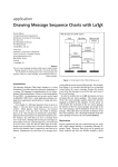
Figure 1 presents a gallery of diagrams created by
Listen to music
Read a book
MetaUML (Gheorghies (2005)).
(and ignore it)
The code which generates these diagrams is quite
straightforward, combining a natural object-oriented
parlance with the power of MetaPost equation solving;
for more information on MetaPost see Hobby (1992).
An UML class, for example, can be defined as fol- C. Use case diagram
lows:
Authenticate user
Class.A("MyClass")
("attr1: int", "attr2: int")
("method1(): void", "method1(): void");
This piece of code creates an instance of Class,
which will be afterward identified as A. This object has
the following content properties: a name (MyClass), a
list of attributes (attr1, attr2) and a list of methods
(method1, method2). The one thing remaining before
actually drawing A is to set its location:
User
Database
Authenticate by
username, password
Authenticate by
smartcard
D. State machine diagram
Working
Reading commands
A.nw = (0, 0);
drawObject(A);
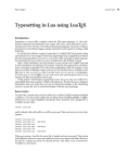
In A.nw we refer to the “north-west” of the class
rectangle, that is to its upper-left corner. In general,
every MetaUML object has the positioning properties
given in figure 2. These properties are used to set
where to draw a given object, whether by assigning
them absolute values, or by setting them relatively
Query database
Preparing error report
error
Processing commands
Writing result
Figure 1. UML diagrams created by MetaUML.
65
66
Ovidiu Gheorghieş
MAPS 33
top
nw
height
w
bottom sw
n
Test
ne
a1
a2
c
e
a3
aLongMethod():void
se
s
width
left
right
Figure 2. Positioning properties of any MetaUML object
(here a class object is depicted).
to other objects. Suppose that we have defined two
classes A and B. Then the following code would give a
conceivable positioning:
A.nw = (0,0);
B.e = A.w + (-20, 0);
B
A
Figure 3. Example of MetaUML. Everything else works
the same.
Point
x:int
y:int
set(x:int, y:int)
getX():int
getY():int
debug():void
Figure 4. Class usage: name, attributes, methods and
visibility markers.
link(inheritance)(B.e -- A.w);
endfig;
end
From a user’s perspective, this is all there is to
MetaUML.
With a reference describing how other UML
After the objects are drawn, one may draw links
elements
are
created, one can set out to typeset arbitbetween them, such as inheritance or association relarary
complex
diagrams.
tions between classes in class diagrams, or transitions
between states in state machine diagrams. Whichever
the purpose is, MetaUML provides a generic way of Class Diagrams
drawing an edge in a diagram’s graph:
A class is created as follows:
link(how-to-draw-information)(path-to-draw);
The “how to draw information” is actually an object
which defines the style of the line (e.g. solid, dashed)
and the appearance of the heads (e.g. nothing, arrow, diamond). One such object, called inheritance,
defines a solid path ending in a white triangle. The
path-to-draw parameter is simply a MetaPost path.
For example, the following code can be used used to
represent that class B is derived from A:
Class.name(class-name)
(list-of-attributes)
(list-of-methods);
The suffix name gives a name to the Class object (which, of course, represents an UML class).
The name of the UML class is a string given by
class-name; the attributes are given as a comma
separated list of strings, list-of-attributes; the
methods are given as a comma separated list of strings,
link(inheritance)(B.e -- A.w);
list-of-attributes. The list of attributes and the
Note that the direction of the path is important, and list of methods may be void.
MetaUML uses it to determine the type of adornment
Each of the strings representing an attribute or
to attach at the link ends (if applicable). In our ex- a method may begin with a visibility marker: “+”
ample, a white triangle, denoting inheritance, points for public, “#” for protected and “−” for private.
towards the end of the path, that is towards class A.
MetaUML interprets this marker and renders a graphic
To sum up, we present a short code and the result- stereotype in form of a lock which may be opened,
ing diagram (figure 3). This is typical for everything semi-closed and closed, respectively.
else in MetaUML. The positioning of A does not need
The following code yields the diagram in figure 4.
to be explicitly set because “floating” objects are auto- Class.A("Point")
matically positioned at (0,0) by their draw method.
("#x:int", "#y:int")
input metauml;
beginfig(1);
Class.A("A")()();
Class.B("B")()();
B.e = A.w + (-20, 0);
drawObjects(A, B);
("+set(x:int, y:int)",
"+getX():int",
"+getY():int",
"-debug():void");
drawObject(A);
An Introduction to MetaUML
«interface»
«home»
User
Figure 5. Class usage: stereotypes.
Vector
T
size: int
NAJAAR 2005
Suppose that we have the declared two points, A (on
the left) and B (on the right):
pair A, B;
A = (0,0);
B = (50,0);
Bidirectional association.
link(association)( A -- B );
Figure 6. Class usage: templates.
Unidirectional association.
link(associationUni)( A -- B );
Stereotypes
After a class is created, its stereotypes may be specified
by using the macro classStereotypes:
Inheritance. link(inheritance)( A -- B );
classStereotypes.name(list-of-stereotypes);
Aggregation. link(aggregation)( A -- B );
Here, name is the object name of a previously created class and list-of-stereotypes is a comma
separated list of strings. Here is an example along with Unidirectional aggregation.
the resulting diagram (figure 5).
link(aggregationUni)( A -- B );
Class.A("User")()();
classStereotypes.A("<<interface>>", "<<home>>");
Composition. link(composition)( A -- B );
drawObject(A);
Unidirectional composition.
Parametrized Classes (Templates)
link(compositionUni)( A -- B );
The most convenient way of typesetting a class template in MetaUML is to use the macro ClassTemplate.
This macro creates a visual object which is appropriAssociations
ately positioned near the class object it adorns.
In UML an association typically has two of association
ClassTemplate.name(list-of-templates)
ends and may have a name specified for it. In turn,
(class-object);
each association end may specify a multiplicity, a role,
The name is the name of the template object, a visibility, an ordering. These entities are treated in
list-of-templates is a comma separated list of MetaUML as pictures having specific drawing informstrings and the class-object is the name of a class ation (spacings, font).
object.
The first method of creating association “items” is
The code below results in the diagram from figure by giving them explicit names. Having a name for an
6.
association item comes in handy when referring to its
properties is later needed (see the non UML-compliant
Class.A("Vector")()();
diagram in figure 7). Note that the last parameter of
ClassTemplate.T("T", "size: int")(A);
the macro item is an equation which uses the item
name to perform positioning.
drawObjects(A, T);
The macro Template can also be used to create a
template object, but this time the resulting object can
be positioned freely.
Class.P("Person")()();
Class.C("Company")()(); % drawing code ommited
Template.name(list-of-templates);
item.aName(iAssoc)("works for")
(aName.s = .5[P.w, C.w]);
draw aName.n -- (aName.n + (20,20));
label.urt("association name" infont "tyxtt",
aName.n + (20,20));
Of course, one can specify both stereotypes and template parameters for a given class.
Types of Links
In this section we enumerate the relations that can be
drawn between classes by means of MetaUML macros.
However, giving names to every association item
may become an annoying burden (especially when
67
68
Ovidiu Gheorghieş
MAPS 33
association name
Person
Company
works for
User
Figure 7. Referring to the properties of association items.
Person
employee
1..*
works for
employer
0..*
Figure 10. Actor example.
Company
Figure 8. Anonymous association items.
Administrator
Authenticate user
by name, password
Figure 9. Usecase example.
there are many of them). Because of this, MetaUML
also allows for “anonymous items”. In this case, the
positioning is set by an equation which refers to the
anonymous item as obj (figure 8).
% P and C defined as in the previous example
item(iAssoc)("employee")(obj.sw = P.e);
item(iAssoc)("1..*")(obj.nw = P.e);
% other items are drawn similarly
Use Case Diagrams
Use Cases
An use case is created by the macro Usecase:
Figure 11. Actor example, accessing the “human”.
Actor.A("User");
drawObject(A);
Note that one may prefer to draw diagram relations
positioned relatively to the visual representation of an
actor (the “human”) rather than relatively to the whole
actor object (which also includes the text). Because
of that, MetaUML provides access to the “human” of
every actor object actor by means of the sub-object
actor.human. Figure 11 gives the result of the code
below:
Actor.A("Administrator");
drawObject(A);
draw objectBox(A);
draw objectBox(A.human);
Note that in MetaUML objectBox(X) is equivalent to X.nw -- X.ne -- X.se -- X.sw -- cycle
for every object X.
Types of Links
Some of the types of links defined for class diagrams
The list-of-lines is a comma separated list of (such as inheritance, association etc.) can be used with
strings. These strings are placed on top of each other, similar semantics within use case diagrams.
centered and surrounded by the appropriate visual
UML notation.
Activity Diagrams
Use case example (result in figure 9):
Begin and End
Usecase.U("Authenticate user",
The begin and the end of an activity diagram can be
"by name, password");
marked by using the macros Begin and End, respectdrawObject(U);
ively. The constructors of these visual objects take no
parameters:
Actors
Usecase.name(list-of-lines);
An actor is created by the macro Actor:
Actor.name(list-of-lines);
Here, list-of-lines represents the actor’s name.
For convenience, the name may be given as a list
of strings which are placed on top of each other, to
provide support for the situations when the role is
quite long. Otherwise, giving a single string as an argument to the Actor constructor is perfectly fine.
Actor example (result in figure 10):
Begin.beginName;
End.endName;
Figure 12 gives the output of the code:
Begin.b;
End.e;
b.nw = (0,0);
e.nw = (20, 20);
drawObjects(b, e);
An Introduction to MetaUML
NAJAAR 2005
Composite
Figure 12. Begin and end in an activity diagram.
Component
Learn MetaUML the MetaPost UML library
Figure 13. Activity example.
Take order
Figure 15. State example: composite states.
Composite States
A composite state is defined by enumerating at the
end of its constructor the inner states. Interestingly
Activity
enough, the composite state takes care of drawing the
An activity is constructed as follows:
sub-states it contains. The transitions must be drawn
Activity.name(list-of-strings);
after the composite state, as seen in the next example
The parameter list-of-strings is a comma sep- (figure 15):
arated list of strings. These strings are centered on Begin.b;
top of each other to allow for the accommodation of a End.e;
longer activity description within a reasonable space. State.c("Component")();
An example is given in figure 13
State.composite("Composite")(b, e, c);
Figure 14. State example.
Activity.A("Learn MetaUML -",
"the MetaPost UML library");
drawObject(A);
b.midx = e.midx = c.midx;
c.top = b.bottom - 20;
e.top = c.bottom - 20;
Types of Links
In activity diagrams, transitions between activities are composite.info.drawNameLine := 1;
needed. They are typeset as in the example below. Fig- drawObject(composite);
ure 15 shows such a transition rendered. This type of
link(transition)(b.s -- c.n);
link is also used for state machine diagrams.
link(transition)( pointA -- pointB );
link(transition)(c.s -- e.n);
Internal Transitions
Internal transitions can be specified by using the
The constructor of a state allows for aggregated sub- macro:
states:
stateTransitions.name(list-transitions);
State Diagrams
State.name(state-name)(substates-list);
The parameter state-name is a string or a list of
comma separated strings representing the state’s name
or description. The substates-list parameter is
used to specify the substates of this state as a comma
separated list of objects; this list may be void.
Figure 14 presents a simple state, rendered by the
following code:
State.s("Take order")();
drawObject(s);
Identifier name gives the state object whose internal transitions are being set, and parameter
list-transitions is a comma separated string list.
Figure 16 presents the result of the code below.
State.s("An interesting state",
"which is worth mentioning")();
stateTransitions.s(
"OnEntry / Open eyes",
"OnExit / Sleep well");
s.info.drawNameLine := 1;
drawObject(s);
69
70
Ovidiu Gheorghieş
MAPS 33
B
An interesting state
which is worth mentioning
A
OnEntry / Open eyes
OnExit / Sleep well
Figure 18. Manhattan paths.
Figure 16. State example: internal transitions.
can choose to reverse it by using rpathManhattanX
and rpathManhattanY (note the prefix “r”):
pathManhattanX(A, B)
pathManhattanY(A, B)
Figure 17. Link paths can be arbitrary complex in
MetaUML: the heads are properly drawn.
rpathManhattanX(A, B)
rpathManhattanY(A, B)
Figure 18 shows these macros at work:
Class.A("A")()();
Class.B("B")()();
Special States
Similarly to the usage of Begin and End macros, one
can define history states, exit/entry point states and B.sw = A.ne + (10,10);
terminate pseudo-states, by using the following con- drawObjects(A, B);
structors.
History.nameA;
ExitPoint.nameB;
EntryPoint.nameC;
Terminate.nameD;
Drawing Paths
The link macro is powerful enough to draw relations
following arbitrary paths (figure 17):
za =
zb =
path
cool
(10,10);
(80,-10);
cool;
:= za .. za+(20,10) ..
zb+(20,-40) ..
zb+(-10,-30) -- zb;
link(aggregationUni)(cool);
Regardless of how amusing this feature might be, it
does become a bit of a nuisance to use it in its bare
form. When typesetting UML diagrams in good style,
one generally uses rectangular paths. It is for this kind
of style that MetaUML offers extensive support, providing a “syntactic sugar” for constructs which can otherwise be done by hand, but with some extra effort.
Manhattan Paths
The “Manhattan” path macros generate a path
between two points consisting of one horizontal and
one vertical segment. The macro pathManhattanX
generates first a horizontal segment, while the macro
pathManhattanY generates first a vertical segment. In
MetaUML it also matters the direction of a path, so you
link(aggregationUni)
(rpathManhattanX(A.e, B.s));
link(inheritance)
(pathManhattanY(A.n, B.w));
Stair Step Paths
These path macros generate stair-like paths between
two points. The “stair” can “rise” first in the direction
of Ox axis (pathStepX) or in the direction of Oy axis
(pathStepY). How much should a step rise is given
by an additional parameter, delta. Again, the macros prefixed with “r” reverse the direction of the path
given by their unprefixed counterparts.
pathStepX(A, B, delta)
pathStepY(A, B, delta)
rpathStepX(A, B, delta)
rpathStepY(A, B, delta)
Figure 19 shows these macros at work:
stepX:=60;
link(aggregationUni)
(pathStepX(A.e, B.e, stepX));
stepY:=20;
link(inheritance)
(pathStepY(B.n, A.n, stepY));
Horizontal and Vertical Paths
There are times when drawing horizontal or vertical
links is required, even when the objects are not properly aligned. To this aim, the following macros are use-
An Introduction to MetaUML
NAJAAR 2005
stepY
B
B
A
A
Figure 21. The pathCut macro at work.
stepX
B
Figure 19. Stair step paths.
A
C
foo: int
Figure 22. Direct linking between objects with clink.
untilY
B
b
A
untilX
Figure 20. Horizontal and vertical paths.
ful:
pathHorizontal(pA, untilX)
pathVertical(pA, untilY)
rpathHorizontal(pA, untilX)
rpathVertical(pA, untilY)
There are times however this may yield unsatisfactory visual results, especially when the appearance of
the object’s corners is round. MetaUML provides the
macro pathCut whose aim is to limit a given path exactly to the region outside the actual borders of the
objects it connects. The macro’s synopsis is:
pathCut(thePath)(objectA, objectB)
Here, thePath is a given MetaPost path and
objectA and objectB are two MetaUML objects. By
contract, each MetaUML object of type, say, X defines
a macro X_border which returns the path that surrounds the object. Because of that, pathCut can make
the appropriate modifications to thePath.
The following code demonstrates the benefits of the
pathCut macro (figure 21):
A path created by pathHorizonal starts from the
point pA and continues horizontally until coordinate z = A.se + (30, -10);
untilX is reached. The macro pathVertical con- link(transition)
structs the path dually, working vertically. The prefix
(pathCut(A, B)(A.c--z--B.c));
“r” reverses the direction of the path.
Direct Paths between Centers. At times is quicker to
Figure 20 gives an usage example:
just draw direct paths between the center of two obuntilX := B.left;
jects, minding of course the object margins. The macro
link(association)
which
does this is clink:
(pathHorizontal(A.e, untilX));
clink(how-to-draw-information)(objA, objB);
untilY:= C.bottom;
link(association)
(pathVertical(A.n, untilY));
Direct Paths
A direct path can be created with directPath. The
call directPath(A, B) is equivalent to A -- B.
The parameter how-to-draw-information is the
same as for the macro link; objA and objB are two
MetaUML objects.
Figure 22 gives the output of the following code:
clink(inheritance)(A, B);
The MetaUML Infrastructure
Paths between Objects
Using the constructs presented above, it is clear that
one can draw links between diagram objects, using a
code like:
link(transition)(directPath(objA.nw, objB.se));
MetaPost is a macro language based on equation solving. Using it may seem quite tricky at first for a programmer accustomed to modern object-oriented languages. However, the great power of MetaPost consists in its versatility. Indeed, it is possible to write a
71
72
Ovidiu Gheorghieş
MAPS 33
yummy
cool
yummy
cool
yummy
cool
yummy
cool
Figure 23. Motivation for not using boxes: the bottom
alignment is imperfect.
system which mimics quite well object-oriented behavior. Along this line, METAOBJ (Roegel (2002)) is a
library worth mentioning: it provides a high-level objects infrastructure along with a battery of predefined
objects.
Surprisingly enough, MetaUML does not use
METAOBJ. Instead it uses a custom written, lightweight object-oriented infrastructure, provisionally
called “util”. The fact that METAOBJ’s source consists of a huge file which is rather hard to follow and
understand contributed to this decision.
Another library that has some object-oriented traits
is the boxes library, which comes with the standard
MetaPost distribution. Early versions of MetaUML did
use boxes as an infrastructure, but eventually it had
to be abandoned. The main reason was that it was
difficult to achieve good visual results when stacking
texts (more on that further on). Also, it had a degree
of flexibility which became apparent to be insufficient.
Motivation
Suppose that we want to typeset two texts with their
bottom lines aligned, using boxit (figure 23):
boxit.a ("yummy");
boxit.b ("cool");
Figure 24. Misalignment occurs by default with the util
library, but this can be configured not to happen.
yummy
cool
yummy
cool
Figure 25. The util package provides good alignment.
iPict.ignoreNegativeBase := 1;
Picture.a("yummy");
Picture.b("cool");
% the rest the same as above
drawObjects(a, b);
The Picture Macro
We
have
seen
previously
the
line
iPict.ignoreNegativeBase := 1. Who is iPict
and what is it doing in our program? MetaUML aims
at separating the “business logic” (what to draw) from
the “interface” (how to draw). In order to achieve
this, it records the “how to draw” information within
the so-called Info structures. The object iPict is an
instance of PictureInfo structure, which has the
following properties (or attributes):
left, right, top, bottom
ignoreNegativeBase
boxed, borderColor
The first four attributes specify how much space
should be left around the actual item to be drawn.
The marvelous effect of ignoreNegativeBase has
drawboxed (a, b); % or drawunboxed(a,b)
just been shown (off) while the last two attributes
draw a.sw -- b.se dashed evenly
control whether the border should be drawn (when
withpen pencircle scaled 1.1;
Note that “yummy” looks slightly higher than “cool”: boxed=1) and if drawn, in which color.
There’s one more thing: the font to typeset the text
this is unacceptable when, in an UML class diagram,
in.
This is specified in a FontInfo structure which has
roles are placed at the ends of a horizontal association.
two
attributes: the font name and the font scale. This
Regardless of default spacing being smaller in the util
library, the very same unfortunate misalignment effect information is kept within the PictureInfo structure
as a contained attribute iFont. Both FontInfo and
rears its ugly head (figure 24):
PictureInfo have “copy constructors” which can be
Picture.a("yummy");
used to make copies. We have already the effect of
Picture.b("cool");
these copy constructors at work, when we used:
a.nw = (0,0); b.sw = a.se + (10,0);
% comment next line for unboxed
a.info.boxed := b.info.boxed := 1;
b.sw = a.se + (10,0);
drawObjects(a, b);
However, the strong point of util is that we have a
recourse to this problem (figure 25):
Picture.a("yummy");
a.info.boxed := 1;
A copy of the default info for a picture, iPict, has
been made within the object a and can be accessed as
a.info. Having a copy of the info in each object may
seem like an overkill, but it allows for a fine grained
control of the drawing mode of each individual object.
An Introduction to MetaUML
NAJAAR 2005
yummy
cool
fool
yummy
cool
Figure 27. Stacking objects.
Figure 26. Having predefined configurations yields short,
convenient code.
This feature comes in very handy when working with a
large number of settings, as it is the case for MetaUML.
Let us imagine for a moment that we have two types
of text to write: one with a small font and a small margin and one with a big font and a big margin. We could
in theory configure each individual object or set back
and forth global parameters, but this is far for convenient. It is preferable to have two sets of settings and
specify them explicitly when they are needed. The following code could be placed somewhere in a configuration file and loaded before any beginfig macro:
PictureInfoCopy.iBig(iPict);
iBig.left := iBig.right := 20;
iBig.top := 10;
iBig.bottom := 1;
iBig.boxed := 1;
iBig.ignoreNegativeBase := 1;
iBig.iFont.name := defaultfont;
iBig.iFont.scale := 3;
PictureInfoCopy.iSmall(iPict);
iSmall.boxed := 1;
iSmall.borderColor := green;
fool
cool
yummy
Figure 28. Grouping objects.
joinObjects(scantokens listArray(a)(3));
drawObjects(scantokens listArray(a)(3));
% or drawObjects (a0, a1, a2);
The listArray macro provides here a shortcut for
writing a0, a1, a2. This macro is particularly useful for generic code which does not know beforehand
the number of elements to be drawn. Having to write
the scantokens keyword is admittedly a nuisance, but
this is required.
The Group Macro
It is possible to group objects in MetaUML. This feature is the cornerstone of MetaUML, allowing for the
easy development of complex objects, such as composite stats in state machine diagrams.
Similarly to the macro Picture, the structure
GroupInfo is used for specifying group properties;
its default instantiation is iGroup. Furthermore, the
macro EGroup explicitely sets the layout information.
Figure 28 results from the code below:
Below is an usage example of these definitions
(result in figure 26). Note the name of the macro:
EPicture. The prefix comes form “explicit” and it’s
used to acknowledge that the “how to draw” informa- iGroup.left:=20;
tion is set explicitly, as opposed to the Picture macro iGroup.right:=15;
iGroup.boxed:=1;
where the info member defaults to iPict.
EPicture.a(iBig)("yummy");
EPicture.b(iSmall)("cool");
% you can still modify a.info and b.info
b.sw = a.se + (10,0);
iPicture.boxed:=1;
Picture.a("yummy");
Picture.b("cool");
Picture.c("fool");
drawObjects(a, b);
b.nw = a.nw + (20,20); % A
c.nw = a.nw + (15, 40); % B
Stacking Objects
It is possible to stack objects, much in the style of
setboxjoin from boxes library (figure 27).
Group.g(a, b, c);
g.nw = (10,10); % C
Picture.a0("yummy");
Picture.a1("cool");
Picture.a2("fool");
drawObject(g);
setObjectJoin(pa.sw = pb.nw);
Note that after some objects are grouped, they can
all be drawn by invoking the drawObject macro solely
on the group that aggregates them. Another important remark is that it is necessary only to set the relative positioning of objects within a group (line A and
73
74
Ovidiu Gheorghieş
MAPS 33
foo
bar: int
nicely-centered
nice
Figure 29. An example of a picture stack.
B); afterward, one can simply “move” the group to a
given position (line C), and all the contained objects
will move along.
in relation to each other within the component
2 where to draw
For example, in order to draw a picture object we
must know, respectively:
2 what is the text or the native picture that needs to
be drawn
2 what are the margins that should be left around
the contents
2 where is the picture to be drawn
The PictureStack Macro
The PictureStack macro is a syntactic sugar for a set
of pictures, stacked according to predefined equations
and grouped together (figure 29).
Why do we bother with these questions? Why don’t
we just simply draw the picture component as soon
as it was created and get it over with? That is, why
doesn’t the following code just work?
iStack.boxed := 1;
iStack.iPict.boxed := 1;
PictureStack.myStack("foo",
"bar: int" infont "tyxtt",
"nicely-centered" infont defaultfont,
"nice")("vcenter");
Picture.pict("foo");
drawObject(myStack);
Note
the
last parameter of the macro
PictureStack, here vcenter. It is used to generate appropriate equations based on a descriptive
name. The spacing between individual picture objects
is set by the field iStack.spacing. Currently, the following alignment names are defined: vleft, vright,
vcenter, vleftbase, vrightbase, vcenterbase.
All these names refer to vertical alignment (the prefix
“v”); alignment can be at left, right or centered. The
variants having the suffix “base” align the pictures so
that iStack.spacing refer to the distance between
the bottom lines of the pictures. The unsuffixed variants use iStack.spacing as the distance between
one’s bottom line and the next’s top line.
The “base” alignment is particularly useful for
stacking text, since it offers better visual appearance
when iPict.ignoreNegativeBase is set to 1.
Components Design
Each
MetaUML component (e.g.
Picture,
PictureStack, Class) is designed according to
an established pattern. This section gives more insight
on this.
In order to draw a component, one must know the
following information:
2 what to draw, or what are the elements of a
component.
2 how to draw, or how are the elements positioned
Well, although we have the answer to question 1
(what to draw), we still need to have question 3
answered. The code below becomes thus a necessity
(actually, you are not forced to specify the positioning
of an object, because its draw method positions it to
(0,0) by default):
% question 1: what to draw
Picture.pict("foo");
% question 3: where to draw
pict.nw = (10,10);
% now we can draw
drawObject(pict);
How about question 2, how to draw? By default,
this problem is addressed behind the scenes by the
component. This means, for the Picture object, that
a native picture is created from the given string, and
around that picture certain margins are placed, by
means of MetaPost equations. (The margins come in
handy when one wants to quickly place Picture objects near others, so that the result doesn’t look too
cluttered.) If these equations were defined within the
Picture constructor, then an usability problem would
have appeared, because it wouldn’t have been possible
to modify the margins, as in the code below:
% question 1: what to draw
Picture.pict("foo");
% question 2: how to draw
pict.info.left := 10;
pict.info.boxed := 1;
% question 3: where to draw
pict.nw = (0,0);
An Introduction to MetaUML
NAJAAR 2005
AB
|AA 0 |
|BB 0 |
% now we can draw
drawObject(pict);
To allow for this type of code, the equations that
define the layout of the Picture object (here, what
the margins are) must be defined somewhere after
the constructor. This is done by a macro called
Picture_layout. This macro defines all the equations which link the “what to draw” information to the
“how to draw” information (which in our case is taken
from the info member, a copy of iPict). Nevertheless, notice that Picture_layouts is not explicitly invoked. To the user’s great relief, this is taken care of
automatically within the Picture_draw macro.
There are times however, when explicitly invoking
a macro like Picture_layout becomes a necessity.
This is because, by contract, it is only after the layout
macro is invoked that the final dimensions (width,
height) of an object are definitely and permanently
known. Imagine that we have a component whose job
is to surround in a red-filled rectangle some other objects. This component needs to know what the dimensions of the contained objects are, in order to be able to
set its own dimensions. At drawing time, the contained
objects must not have been drawn already, because the
red rectangle of the container would overwrite them.
Therefore, the whole pseudo-code would be:
Create objects o1, o2, ... ok;
Create container c(o1, o2, ..., ok);
Optional: modify info-s for o1, o2, ... ok;
Optional: modify info for c;
A
the path specified by the user
iLink.widthA
iLink.widthB
A0
B0
B
Figure 30. Details on how a link is drawn by MetaUML.
a diamond. So the template algorithm for drawing a
link is:
0.
1.
2.
3.
Reserve space for heads
Draw the path (except for the heads)
Draw head 1
Draw head 2
Each of the UML link types define how the drawing
should be done, in each of the cases (1, 2 and 3). Consider the link type of unidirectional composition. Its
“class” is declared as:
vardef CompositionUniInfo@# =
LinkInfo@#;
@#widthA
= defaultRelationHeadWidth;
@#heightA
= defaultRelationHeadHeight;
@#drawMethodA = "drawArrow";
@#widthB
= defaultRelationHeadWidth;
@#heightB
= defaultRelationHeadHeight;
@#drawMethodB = "drawDiamondBlack";
@#drawMethod = "drawLine";
enddef;
layout c, requiring layout of o1, o2, ... ok;
establish where to draw c;
draw red rectangle defined by c;
draw components o1, o2, ...ok within c
Using this definition, the actual description is created like this:
Note that an object mustn’t be laid out more than
once, because otherwise inconsistent or superfluous
equations would arise. To enforce this, by contract,
any object must keep record of whether its layout
method has already been invoked, and if the answer
is affirmative, subsequent invocations of the layout
macro would do nothing. It is very important to mention that after the layout macro is invoked over an
object, modifying the info member of that object has
no subsequent effect, since the layout equations are
declared and interpreted only once.
As shown previously, is is the macro link which
performs the actual drawing, using the link description information which is given as parameter (generally called iLink). For example, we can use:
Notes on the Implementation of Links
MetaUML considers edges in diagram graphs as links.
A link is composed of a path and the heads (possible
none, one or two). For example, an association has no
heads, and one must simply draw along the path with
a solid pen. An unidirectional aggregation has a solid
path and two heads: one is an arrow and the other is
CompositionUniInfo.compositionUni;
link(aggregationUni)((0,0)--(40,0));
Let us see now the inner workings of macro link.
Its definition is:
vardef link(text iLink)(expr myPath)=
LinkStructure.ls(myPath,
iLink.widthA, iLink.widthB);
drawLinkStructure(ls)(iLink);
enddef;
First, space is reserved for heads, by “shortening”
the given path myPath by iLink.widthA at the beginning and by iLink.widthB at the end. After that,
the shortened path is drawn with the “method” given
by iLink.drawMethod and the heads with the “methods” iLink.drawMethodA and iLink.drawMethodB,
75
76
Ovidiu Gheorghieş
MAPS 33
A
respectively (figure 30).
B
Object Definitions: Easier generic_declare
C
In MetaPost if somebody wants to define something resembling a class, say Person, he would do something
like this:
Figure 31. Changing the default settings for all classes.
vardef Person@#(expr _name, _age)=
% @# prefix can be seen as ‘this‘ pointer
string @#name;
numeric @#age;
@#name := _name;
@#age := _age;
enddef;
This allows for the creation of instances (or objects)
of class Person by using declarations like:
Person.personA;
Person.personB;
However, if one also wants to able able to create
indexed arrays of persons, such as Person.student0,
Person.student1 etc., the definition of class Person
must read:
vardef Person@#(expr _name, _age)=
_n_ := str @#;
generic_declare(string) _n.name;
generic_declare(numeric) _n.age;
@#name := _name;
@#age := _age;
enddef;
not possibly present all the customization options for
all kinds of MetaUML objects: this would take too long.
Nevertheless, an interested reader can refer to the top
of the appropriate MetaUML library file, where Info
structures are defined. For example, class diagram related definitions are in metauml_class.mp, activity
diagram definitions are in metauml_activity.mp etc.
Global settings
Let us assume that we do not particularly like the
default foreground color of all classes, and wish to
change it so something yellowish. In this scenario, one
would most likely want to change the appropriate field
in iClass:
iClass.foreColor := (.9, .9, 0);
After this, the following code produces the result in
figure 31:
Class.A("A")()();
Class.B("B")()();
Class.C("C")()();
B.w = A.e + (20,0);
C.n = .5[A.se, B.sw] + (0, -10);
This construction is rather inelegant. MetaUML offers alternative macros to achieve the same effect, un- drawObjects(A, B, C);
cluttering the code by removing the need for the unaesIndividual settings
thetic _n_ and _n.
When
one wants to make modifications to the settings
vardef Person@#(expr _name, _age)=
of one particular Class objects, another strategy is
attributes(@#);
more appropriate. How about having class C stand out
var(string) name;
with
a light blue foreground color, a bigger font size
var(numeric) age;
for the class name and a blue border (figure 32)?
@#name := _name;
@#age := _age;
enddef;
Customization in MetaUML: Examples
iPict.foreColor := (.9, .9, 0);
Class.A("A")()();
Class.B("B")()();
Class.C("C")()();
C.info.foreColor := (.9, .7, .7);
C.info.borderColor := green;
C.info.iName.iFont.scale := 2;
We have seen that in MetaUML the “how to draw”
information is memorized into the so-called “Info”
structures. For example, the default way in which a
Picture object is to be drawn is recorded into an in- % positioning code ommited
stance of PictureInfo, named iPict. In this sec- drawObjects(A, B, C);
tion we present a case study involving the customAs an aside, note that for each Class object its info
ization of Class objects. The customization of any member is created as a copy of iClass: the actual
other MetaUML objects works similarly. Here we can-
An Introduction to MetaUML
A
NAJAAR 2005
B
C
Figure 32. Individual customization of a class object.
drawing is performed using this copied information.
Because of that, one can modify the info member after
the object has been created and still get the desired results.
Another thing worth mentioning is that the
ClassInfo structure contains the iName member,
which is an instance of PictureInfo. In our example we do not want to modify the spacings around
the Picture object, but the characteristics of the
font its contents is typeset into. To do that, we
modify the iName.iFont member, which by default
is a copy of iFont (an instance of FontInfo, defined
in util_picture.mp). If, for example, we want to
change the font the class name is rendered into, we
would set the attribute iName.iFont.name to a string
representing a font name on our system (as used with
the MetaPost infont operator).
Predefined settings
The third usage scenario is perhaps more interesting.
Suppose that we have two types of classes which we
want to draw differently. Making the setting adjustments for each individual class object would soon become a nuisance. MetaUML’s solution consists in the
ability of using predefined “how to draw” Info objects.
Let us create such objects:
ClassInfoCopy.iHome(iClass);
iHome.foreColor := (0, .9, .9);
ClassInfo.iRemote;
iRemote.foreColor := (.9, .9, 0);
iRemote.borderColor := green;
Object iHome is a copy of iClass (as it might have
been set at the time of the macro call). Object iRemote
is created just as iClass is originally created. We can
now use these Info objects to easily set the “how to
draw” information for classes. The result is depicted
in figure 33, please note the “E” prefix in EClass:
EClass.A(iHome)("UserHome")()();
EClass.B(iRemote)("UserRemote")()();
EClass.C(iHome)("CartHome")()();
EClass.D(iRemote)("CartRemote")()();
UserHome
UserRemote
CartHome
CartRemote
Figure 33. Using predefined settings.
Foo
a: int
b: int
foo()
bar()
gar()
Figure 34. Extreme customization of a class. You may
want not to do this, after all.
Extreme customization
When another font (or font size) is used, one may also
want to modify the spacings between the attributes’
and methods’ baselines. Figure 34 is the result of the
(unlikely) code:
Class.A("Foo")
("a: int", "b: int")
("foo()", "bar()", "gar()");
A.info.iAttributeStack.iPict.iFont.scale := 0.8;
A.info.iAttributeStack.top := 10;
A.info.iAttributeStack.spacing := 11;
A.info.iMethodStack.iPict.iFont.scale := 2;
A.info.iMethodStack.spacing := 17;
A.info.iMethodStack.bottom := 10;
drawObject(A);
Both iAttributeStack and iMethodStack are instances of PictureStackInfo, which is used to control the display of PictureStack objects.
Conclusions
MetaUML is a GNU GPL library for typesetting UML
diagrams, particularly useful in a TeX or LaTeX environment; see Knuth (1986), Lamport (1994). It
provides an easy to use, human readable API.
The code of a diagram typeset in MetaUML appears clearer (at least to the author of this paper) than
the corresponding code in uml.sty, pst-uml.sty,
umldoc or even XMI; see Gjelstad (2001), Diamantini
(1998), Palmer (1999), OMG (2003). It is the next
best thing to using a visual tool, while having the free-
77
78
Ovidiu Gheorghieş
MAPS 33
dom of not becoming technologically dependent of any
particular visual tool.
The util infrastructure of MetaUML offers means
of defining and using “objects”, which may recommend
it for other typesetting projects, unrelated to UML. We
mention here a few of its benefits: the ability to stack
and align text in a visually pleasing way; a fine degree
of control of how elements are laid out; the ability to
group objects while having access to the properties of
inner elements; a design pattern and syntactic sugar
for writing modern-looking, reusable MetaPost code.
With this infrastructure in place, it should be possible to extend MetaUML until it offers complete UML
2.0 support.
References
Lamport, L. (1994). LaTEX a Document Preparation System. Addison-Wesley Publishing Company, 2nd edition.
Gheorghies, O. (2005).
MetaUML: Tutorial,
Reference and Test Suite.
Available from
http://metauml.sourceforge.net.
Hobby, J. (1992) A User’s Manual for MetaPost. Available from http://www.tug.org/tutorials/mp/.
Gjelstad, E. (2001). uml.sty 0.09.09. Available from
http://heim.ifi.uio.no/˜ellefg/uml.sty/.
Diamantini, M. (1998).
du package pst-uml.
Interface utilisateur
Available from
http://perce.de/LaTeX/pst-uml/.
Roegel, D. (2002).
The METAOBJ tutorial
and reference manual.
Available from
www.loria.fr/ roegel/TeX/momanual.pdf.
Palmer, D. (1999).
The umldoc UML Documentation Package.
Available from
http://www.charvolant.org/˜elements/.
Knuth, D. E. (1986). The TEXbook. Addison-Wesley
Publishing Company.
Object Management Group (2003). XML Metadata
Interchange (XMI) Specification. Available from
http://www.omg.org/.
Ovidiu Gheorghieş
Faculty of Computer Science
“Al. I. Cuza” University of Iaşi
Romania
[email protected]