1
3
1.
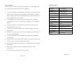
Inputs and Connectors on the LCD monitor:
4. OSD Control Key
1.
1. DC 12 Volt Power Input
2. PC Input
3. S-Video input
4. AV Composite Video input
Auto Key: Automatically adjusts H-Position, V-Position, Pixel Clock
and Phase, for an optimal image.
2.
Up Key:
To increase the value of the chosen item
3.
LED Power Indicator: Green is On, Red is standby.
4. Power Key:
Power ON/OFF
2. Connections
5. Down Key:
To decrease the value of the chosen item
1) Connect the video source to the Video input Connector ( 3 ) for S-Video or
6.
Connector ( 4 ) for AV Composite Video Input or Connector (4) for PC Input.
Menu Key: To enter the main menu of the on-screen display
. Main power on/off
2) Connect the Regulated 12V power supply to Connector ( 1 )
The positive pole must be connected to the center contact.
5.
Trouble Shooting
i.
3. Operation
If power LED is off: check if the power cable is securely
connected.
1) The above in “connections” above must be carried out first.
ii.
If power LED is RED in color: check if the video cable is securely
2) Switch on Main power button to turn on the power. The green LED will light.
connected and you have a video signal. Also check if using PC
3) Select the correct Video Input.
input that your computer is switched on.
4) Use OSD controls to adjust the Brightness and Contrast in order to obtain an
image as clear and sharp as possible.
Page 3 of 6
iii.
If power LED is GREEN in color: check if the H SYNC frequency
is out of range. Adjust the brightness and contrast control.
Page 4 of 6