1
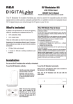
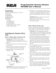
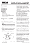
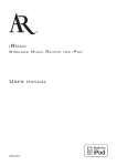
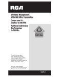
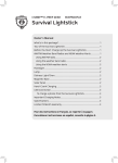
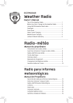
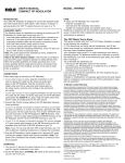
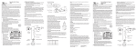
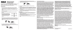
USER’S MANUAL
RF MODULATOR WITH S-VIDEO INPUT
MODEL : CRF910
NOTE TO CATV SYSTEM INSTALLER:
INTRODUCTION
Your Video RF Modulator is designed to convert the separate audio and
video signals (from a video camera, computer, portable VCR, or satellite
receiver, for example) into VHF TV signals that you can view on a TV set.
The FCC Wants You to Know
This device complies with Part 15 of FCC Rules. Operation is subject to
the following two conditions:
(1) This device may not cause harmful interference, and (2) this device
must accept any interference received, including interference that may
cause undesired operation.
Your modulator might cause TV or radio interference even when is
operating properly. To determine whether your modulator is causing the
interference, turn it off. If the interference goes away, your modulator is
causing it.
Try to eliminate the interference by:
• moving your RF Modulator away from the receiver
• connecting your RF Modulator to an outlet that is on a different
electrical circuit from the receiver
• contacting your local store for help
If you cannot eliminate the interference, the FCC requires that you stop
using your RF Modulator.
Changes or modifications not expressly approved by the party
responsible for compliance could void the user’s FCC authorization to
operate this equipment.
REQUIRED PARTS
The following items (not supplied) are required to connect your RF
Modulator to a video input source and your TV.
• one audio/video shielded cable with three phono connectors at each
end, if the video source’s audio output is stereo; or one audio/video
shielded cable with two phono connectors at each end if the video
source’s audio output is monaural
• two 75-ohm coaxial cables with F-type connectors
• a 75-ohm-to-300-ohm matching transformer, if your TV does not have
a VHF 75-ohm F-connector
Note: The audio signal will be modulated to mono, whether the video
source is stereo or monaural.
Note to the CATV System Installer: This reminder is provided to call
the CATV system installer’s attention to article 820-22 of the NEC that
provides guidelines for proper grounding and, in particular, specifies
that the cable ground shall be connected to the grounding system of the
building, as close to the point of cable entry as practical.
INSTALLATION
1. Seat the RF Modulator vertically :
Plug in the seat plate (included) on
the bottom of the RF Modulator until
The locking tab of the seat plate
clicks in to secure the plate to the
RF Modulator.
2. Seat the RF Modulator horizontally :
2.1 While pulling up the
locking tab, remove
the seat plate by
pushing out the seat
plate.
2.2 Attach the four self-adhesive rubber pads (included) to the
side face of the RF Modulator.
Follow these steps to connect your RF Modulator.
1. If your video source is stereo,
plug the connectors on one
end of a stereo A/V cable into
the video and audio input jacks
on the RF Modulator. Plug the
connectors on the cable’s other
end into to video and audio
output jacks on the video source,
using the color coding on the
connectors as a guide.
Video Source
A/V Cable
RF Modulator
If your video source is monaural,
plug the connectors on one end
of an A/V cable into the video
and audio input jacks on the RF
Modulator (using either the AUDIO
R or L jack). Plug the cable’s other
ends into the video and audio
jacks on the video source. Connect
the 75-ohm coaxial cables to the
RF Modulator following these
guidelines:
Video Source
A/V Cable
RF Modulator
ON
2.3 Lay down the RF Modulator on the side with the rubber
pads.
CONNECTIONS
• If your video source is equipment
with VHS VIDEO (S-video) output,
you can use a S-video cable to
connect the S-video output of video
source to the S-video input of this
RF modulator.
Video
Source
RF Modulator
• If your TV is already connected
to another VHF input source
(such as cable, an antenna, or a
VCR, for example), disconnect
the VHF input source’s 75-ohm
cable from the TV’s 75-ohm
VHF/UHF terminal, and reconnect
it to the RF Modulator’s ANT IN
terminal. Then connect a 75-ohm
coaxial cable between the TO TV
terminal on the RF Modulator and
the 75-ohm VHF/UHF terminal on
your TV.
• If your TV is not already
connected to another VHF source,
connect a 75-ohm coaxial cable
between to the TO TV terminal on
the RF modulator and the 75-ohm
VHF/UHF terminal on your TV.
SPECIFICATIONS
A/V Cable
Video Carrier Output Level...............................................69dBμV
RF Output Channels............................................................ 3 or 4
RF Output Impedance....................................................75 Ohms
Audio Input Impedance............................................13±3K Ohms
ANTENNA /CABLE
TV to ANT Insertion Loss 50 - 806 MHz................................ -2dB
VHF/UHF
TV
VHF/UHF
75-Ohm Coaxial Cables
Dimensions............................................ 5 23/32 x 3 x 1 13/64 inches
.......................................................................(145 x 75 x 30 mm)
Weight...................................................................15 oz (.430 kg)
Specifications are typical; individual units might vary.
Specifications are subject to change and improvement without
notice.
A/V Cable
TV
VHF/UHF
12 Month Limited Warranty
75-Ohm
Coaxial Cables
RF Modulator
75-Ohm to 300-Ohm
Matching Transformer
TV
UHF
A/V Cable
VHF
Note: If your TV has only 300ohm VHF screw terminals, use
a 75-ohm-to-300-ohm matching
transformer to complete the
connection.
DC Adapter.............................................................9 VDC/100mA
2. Plug the RF Modulator’s
power cord into a standard
AC outlet. Note: This power
unit is intended to be correctly
oriented in a vertical or floor
mount position.
75-Ohm
Coaxial Cables
RF Modulator
OPERATION
1. Turn on the TV and set it to either Channel 3 or 4. whichever
is not used for regular broadcasts in your area.
2. Set the RF Modulator’s CHANNEL
3/4 switch to the same channel
you set the TV (3 or 4).
CHANNEL 3/4
RF Modulator
CARE
To enjoy your RF Modulator for a long time:
• Keep the modulator dry. If it gets wet, wipe it dry immediately.
• Use and store the modulator only in normal temperature
environments.
• Handle the modulator gently and carefully. Don’t drop it.
• Keep the modulator away from dust and dirt.
• Wipe the modulator with a damp cloth occasionally to keep it
looking new.
Modifying or tampering with the modulator’s internal components
can cause a malfunction and invalidate its warranty and void
your FCC authorization to operate it. If your modulator is not
performing as it should, take it to your local store for assistance.
Audiovox Electronics Corporation (the “Company”) warrants to the
original retail purchaser of this product that should this product or any
part thereof, under normal use and conditions, be proven defective
in material or workmanship within 12 months from the date of original
purchase, such defect(s) will be repaired or replaced (at the Company’s
option) without charge for parts and repair labor. To obtain repair or
replacement within the terms of this Warranty, the product along with
any accessories included in the original packaging is to be delivered
with proof of warranty coverage (e.g. dated bill of sale), specification of
defect(s), transportation prepaid, to the Company at the address shown
below. Do not return this product to the Retailer.
This Warranty is not transferable and does not cover product
purchased, serviced or used outside the United States or Canada. The
Warranty does not extend to the elimination of externally generated
static or noise. This Warranty does not apply to costs incurred for
installation, removal or reinstallation of the product, or, if in the
Company’s opinion, the product has been damaged through acts of
nature, alteration, improper installation, mishandling, misuse, neglect,
accident, or the simultaneous use of different battery types (e.g.
alkaline, standard or rechargeable). This Warranty does not cover
damage caused by an AC adapter not provided with the product.
THE EXTENT OF THE COMPANY’S LIABILITY UNDER THIS
WARRANTY IS LIMITED TO THE REPAIR OR REPLACEMENT
PROVIDED ABOVE AND, IN NO EVENT, SHALL THE COMPANY’S
LIABILITY EXCEED THE PURCHASE PRICE PAID BY PURCHASER
FOR THE PRODUCT.
This Warranty is in lieu of all other express warranties or liabilities. ANY
IMPLIED WARRANTIES, INCLUDING ANY IMPLIED WARRANTY OF
MERCHANTABILITY OR FITNESS FOR A PARTICULAR PURPOSE,
SHALL BE LIMITED TO DURATION OF THIS WARRANTY. ANY
ACTION FOR BREACH OF ANY WARRANTY HEREUNDER,
INCLUDING ANY IMPLIED WARRANTY, MUST BE BROUGHT
WITHIN A PERIOD OF 24 MONTHS FROM THE DATE OF ORIGINAL
PURCHASE. IN NO CASE SHALL THE COMPANY BE LIABLE FOR
ANY CONSEQUENTIAL OR INCIDENTAL DAMAGES WHATSOEVER.
No person or representative is authorized to assume for the Company
any liability other than expressed herein in connection with the sale of
this product.
Some states/provinces do not allow limitations on how long an
implied warranty lasts or the exclusion or limitation of incidental or
consequential damage so the above limitations or exclusions may not
apply to you. This Warranty gives you specific legal rights and you may
also have other rights which vary from state/province to state/province.
U.S.A.: Audiovox Electronics Corporation, 150 Marcus Blvd.,
Hauppauge, New York 11788
CANADA: Audiovox Return Center, c/o Genco, 6685 Kennedy Road,
Unit 3, Door 16, Mississauga, Ontario L5T 3A5
© 2007 Audiovox Accessories Corporation
111 Congressional Blvd., Suite 350
Carmel, IN 46032
PCRF910IB Rev0507
Trademark(s) ®Registered
www.rca.com
Made in China