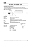
1
nual
en
gli
sh
2-Port Node
Version 1.1x
February 2008
CONTENT
2
Introduction
Quick Start
Examples of use
Layout
Display
Setup
Update
Save / Load Configuration
Mounting
Data sheet
Important safety instructions
Declaration of Conformity
Index
3
5
6
8
10
11
19
20
21
22
23
24
25
MA Lighting Technology GmbH . Dachdeckerstr. 16 . D-97297 Waldbüttelbrunn
Introduction
The grandMA 2-Port Node is the latest member of the grandMA family that seamlessly fits into the network of the MA product range.
The 2-Port Node was designed in view of a decentralized DMX distribution for smaller applications within non-complex networks.
The 2-Port Node can also be integrated into third party systems, as 100Mbit/s and ARTNET offer a great deal of flexibility. It is,
however, not designed as channel expansion of existing grandMA consoles, as this would require additional NSPs.
We also offer alternative versions having varied channel numbers in two different housings and with multiple DMX plug designs.
The flush-mount version for stationary installations has no housing and no separate power supply (PowerIOverEthernet). It is designed
for use in combination with a console only.
The rig-mounted version with housing and an additional separate power supply is designed to be used in a rig or on stage.
All 2-Port Nodes are characterized by their simple operation, their few clear menus, and by the fact that they can easily be integrated
into the network. Furthermore, as members of the grandMA family, they use the same software which means simple configuration and
updates from any grandMA console or the onPC.
For experienced MA operators, using the 2-Port Node will present nothing new, and those using it for the first time will just have to
get familiar with the „onPC“ software. And now: have fun with the 2-Port Node!
Technical Service and Hotline
MA Lighting and its extensive distributor network offer an unparalleled technical service. Call on our expertise for help with any
problem, no matter if it is regarding operation, software features, software installations or trouble shooting.
Please check our Frequently Asked Questions first, that you can find online at www.malighting.com.
If there are any questions left, just send us an e-mail with your contact details and subject information at
[email protected]. We service your request within 48h on working days. This E-Mail Service is monitored during MA
Lightings regular business hours in Germany from 8.30 a.m. until 5 p.m., Monday through Friday. Alternatively you can call our
Technical Support during that time: +49.5251.688865-30.
For emergency services please contact your local distributor or contact the MA Lighting Service Hotline. Call:
+49.5251.688865-99
Please note, this 24/7 hotline is strictly for emergency cases (so-called show stoppers) – for people being in trouble out in the
field. Thank you for your understanding
Technical Service: [email protected]; +49.5251.688865-30
Emergency Line: +49.5251.688865-99
2-Port Node Version 1.1
3
The following design models are available:
- Flush-mount version (Power over Ethernet) with 1,204 parameters, to be sunk-mounted in flush box according to EU standards
Cannot exclusively be operated with the „onPC“ software.
2-Port Node, flush-mounted box „EU version“, 2x DMX in
2-Port Node, flush-mounted box „EU version“, 2x DMX out
2-Port Node, flush-mounted box „EU version“, 1x DMX in, 1x DMX out
- Flush-mount version (Power over Ethernet) with 1,204 parameters, to be sunk-mounted in flush box according to US standards
Cannot exclusively be operated with the „onPC“ software.
2-Port Node, flush-mounted box „US version“, 2x DMX in
2-Port Node, flush-mounted box „US version“, 2x DMX out
2-Port Node, flush-mounted box „US version“, 1x DMX in, 1x DMX out
- Rigging box version ( incl. power supply) with 512 parameters and onPC / 1,024 parameters with console; using metric M12 threads
2-Port Node rig-mounted touring version incl. power supply, „EU version“, 2x DMX in
2-Port Node rig-mounted touring version incl. power supply, „EU version“, 2x DMX out
2-Port Node rig-mounted touring version incl. power supply, „EU version“, 1x DMX in, 1x DMX out
- Rigging box version ( incl. power supply) with 512 parameters and onPC / 1,024 parameters with console; using ½“ 13-UNC screw
threads basing on inch system
2-Port Node rig-mounted touring version incl. power supply, „US version“, 2x DMX in
2-Port Node rig-mounted touring version incl. power supply, „US version“, 2x DMX out
2-Port Node rig-mounted touring version incl. power supply, „US version“, 1x DMX in, 1x DMX out
- Rigging box version (incl. power supply) with 1,024 parameters, using metric M12 threads
2-Port Node PRO rig-mounted touring version incl. power supply, „EU version“, 2x DMX in
2-Port Node PRO rig-mounted touring version incl. power supply, „EU version“, 2x DMX out
2-Port Node PRO rig-mounted touring version incl. power supply, „EU version“, 1x DMX in, 1x DMX out
- Rigging box version (incl. power supply) with 1,024 parameters; using ½“ 13-UNC screw threads basing on inch system
2-Port Node PRO rig-mounted touring version incl. power supply, „US version“, 2x DMX in
2-Port Node PRO rig-mounted touring version incl. power supply, „US version“, 2x DMX out
2-Port Node PRO rig-mounted touring version incl. power supply, „US version“, 1x DMX in, 1x DMX out
If you want to be flexible in using the different variants, we offer DMX cables having distinct plug combinations and appropriate connectors.
4
MA Lighting Technology GmbH . Dachdeckerstr. 16 . D-97297 Waldbüttelbrunn
Quick Start:
These are the basic steps to start up the 2-Port Node:
Mount the 2-Port Node (flush-mount version) in a flush box; install the rig-mounted version using the
fastening screws)
see page 19
Power supply:
Flush-mount: For this version, the switch / hub must support the PowerOnEthernet function
and must deliver sufficient power (approx. 2 Watt) - not for onPC!
Rig-mount: Either operate it via PowerOverEthernet and/or plug the supplied mains cord
into the 2-Port and connect it to a correctly installed wall socket (100-230V, 50-60Hz). You
can work with both operation modes simultaneously – no need to define or select any; on
power failure, the 2-Port will automatically switch over to the available power source.
Install onPC on a PC or laptop computer
or
Switch on the grandMA console
Connect the 2-Port using a network cable (RJ45 plug). Either via the switch / hub or by directly
plugging it into a PC or laptop computer (not valid for flush-mount version) - - no cross-cable!
Start a session from the console or in onPC
On the console / onPC open the TOOLS / MA NETWORK CONFIGURTAIONS / 2 PORT menu.
If needed, set the software version – if the „Version“ cell is highlighted in red,
see page 18
Set the IP-address of the 2-Port Node (press the SHOW ALL button). If there are several 2-Port
Nodes on the network, you can find each of them using the IDENTIF button – the display and the
LED of the selected Node will blink);
see page 11
Name the 2-Port (optional)
Set the MA NET or ARTNET mode
Set the session ID (only MANET) - must be identical to the one set on the console or in onPC
Set the ports,
see page 12
Connect the DMX cables
Technical Service: [email protected]; +49.5251.688865-30
Emergency Line: +49.5251.688865-99
2-Port Node Version 1.1
5
Examples of use
Switch / hub
100 Mbit
Installation:
The network must be of a 100Mbit type.
Options:
Output: 2x512 parameters / 2 Universes max. (i.e.
all channels output must be patched in the two
Universes.)
DMX A -out / in (512 parameter)
DMX B -out / in (512 parameter)
Example of use 1
Switch / hub
100 Mbit
DMX B -IN (512 parameter)
DMX A -OUT / IN (512 parameter)
Example of use 2
Example of use 3
6
MA Lighting Technology GmbH . Dachdeckerstr. 16 . D-97297 Waldbüttelbrunn
Examples of use
DMX-out (max. 512 parameter)
Example of use 4
Switch / hub
100 Mbit
The flush-mount version has a special feature:
Although in the flush-version, the 2-Port can only
cooperate with a grandMA console, the laptop running
the onPC software would bridge a console breakdown
(see example on the left), carry on as Session Master
and produce DMX outputs. Using an onPC as backup,
however, is not a good solution.
Example of use 5
DMX A -OUT / IN (512 parameter)
DMX B -OUT / IN (512 parameter)
Technical Service: [email protected]; +49.5251.688865-30
Emergency Line: +49.5251.688865-99
2-Port Node Version 1.1
7
Layout
SURFACE-MOUNTING
With power supply over the network
(PowerOverEthernet) and additionally with the integrated
110/220V 50-60Hz power supply unitWith power supply
over the network (PowerOverEthernet) and additionally
with the integrated 110/220V 50-60Hz power supply unit
The 2-Port can be operated by means of PowerOverEthernet
or by an external power supply or from both sources
simultaneously – no need to set or activate itThe 2-Port can
be operated by means of PowerOverEthernet or by an
external power supply or from both sources simultaneouslyno need to set or activate it.
- ETHERNET 10/100 - base T/X
For RJ45 plug connection
- Power supply with fuse T1A, L250V
- LED Power
Will be on while external power supply or
PowerOverEthernet
- Display
- DATA A DMX OUT or IN
- LED (green) DATA
Will be on while transferring data via the A port
- DATA B DMX OUT or IN
- LED (green) DATA
Will be on while transferring data via the B port
- Button (red) MENU
To step through the menus
- 2 M12 bolts – on the back side and on the top cover;
for fastening on the rig.
8
MA Lighting Technology GmbH . Dachdeckerstr. 16 . D-97297 Waldbüttelbrunn
Layout
FLUSH-MOUNTINGFLUSH-MOUNTING
Only with power supply over the networkOnly with power supply over
the network
(PowerOverEthernet) - cannot exclusively be operated with the „onPC“
software(PowerOverEthernet) - cannot exclusively be operated with the „onPC“
software
- ETHERNET 10/100 - base T/X
For RJ45 plug connection
(on the back side, not visible here)
- Display
- DATA A DMX OUT or IN
- LED (green) DATA
Will be on while transferring data via the A port
- DATA B DMX OUT or IN
- LED (green) DATA
Will be on while transferring data via the B port
- Button (red) MENU
To step through the menus.
Technical Service: [email protected]; +49.5251.688865-30
Emergency Line: +49.5251.688865-99
2-Port Node Version 1.1
9
Display
The 2-Port Node display will only show the most important settings. For configuring a node,
you have to use a grandMA console or the „onPC“ software.
after switching the device on, the display will show:
Name of 2-Port Node
Universe and Merge Mode Port1 and Port2
e.g.
MA Node No1
2 LoTP 4 OUT
pressing the MENU button briefly
Mode
Session ID or ARTNET ID
MA NET
Session ID:3
e.g.
or
ARTNET
2 .102.240.3
pressing the MENU button briefly
IP Adress of 2-Port Node
Subnetmask of 2-Port Node
e.g.
192.168.0.213
255.255.255.0
After a brief moment, the display will switch back to the first menu.
Keep the button MENU pressed and....
...release after approx. 2 seconds
The first line will show the 2-Port Node serial number and the software version.
The second line will show the 2-Port Node type.
empty = onPC not available / onPC = 512 parameter version / onPC_PRO = 1,024 parameter version
...after approx. 5 seconds IDENTIFY MODE is shown on the display. Now release the button.
The green LED and the display will blink to identify, and the console menu, the 2-Port Node line will blink in green.
Pressing the MENU or IDENTIFY button on the console or in onPC will stop the blinking.
...after approx. 8 seconds....
- If the 2-Port is in MA NET mode: ARTNET OUT / OUT — IN /OUT — IN/IN release the button, if you reach the desired ARTNET
setting. The subnet and channel numbers must be set from the Artnet console.
- If the 2-Port is in ARTNET mode: MA Net Switch the 2-Port Node will be switched to the MA NET mode, when you release the button.
...after approx.10 seconds RESET / RESTORE MODE is shown on the display.
- now release the button.
Will reset the 2-Port Node, i.e. will reboot the device. All settings will be kept.
- or press the button anew
Will restore the 2-Port Node to factory default.
10
MA Lighting Technology GmbH . Dachdeckerstr. 16 . D-97297 Waldbüttelbrunn
Entering / Changing a setting:
You can only make changes from the console or the onPC (on a laptop or PC).
On the console or in onPC, open the TOOLS / MA NETWORK CONFIGURTAIONS
/ 2 PORT menu.
Select the 2-Port Node you want – the cell in the respective row will be
highlighted in blue then. Just to make sure, press the IDENTIFY button – the LED
and the display for the selected 2-Port Node will blink. Press the button again to
stop the blinking.
Select the desired cell. If you use the right mouse button or Encoder on the
console, the respective dialog window for entries will open immediately.
IP-address:
Here, you can set the IP-address for the 2-Port Node. The first 3 groups must
correspond to the other elements in the same network. The fourth group must be
set individually for this device and must be unique in this network.
In the TOOLS / MA NETWORK CONFIGURATIONS / 2-PORT menu, select
the IP cell making a mouse click or pressing the Encoder (cell will receive a blue
background) – this will automatically open the edit box.
In the edit box, enter the IP-address – us a dot to separate the number groups
consisting of 3 digits each.
Confirm using the OK button. This will automatically close the edit box.
Make sure that the desired IP-address appears in the IP cell.
Name: 18 digits max. (incl. special characters) - optional, entries are not
mandatory.
Here, you can enter the name of the 2-Port Node. This entry helps you to discern
the nodes when using several of them. You can, however, use the same name
more than once. If you make no entry, the default name will appear.
In the TOOLS / MA NETWORK CONFIGURATIONS / 2-PORT menu, select
the NAME cell making a mouse click or pressing the Encoder (cell will receive a
blue background) – this will automatically open the edit box.
Enter the name in the respective edit box.
Confirm using the OK button. This will automatically close the edit box.
Make sure that the desired name appears in the NAME cell.
Technical Service: [email protected]; +49.5251.688865-30
Emergency Line: +49.5251.688865-99
2-Port Node Version 1.1
11
Mode
Here, you can set the protocol to be used between the devices.
MA NET
If you only have MA LIGHTING devices (consoles of the grandMA series and the
„onPC“ software) in the network, you can select MA Net as protocol.
In the MA NET –ode, you can set no other parameters.
ARTNET
In order to cooperate with other lighting consoles, the 2-Port Node can be run as
ARTNET Node. If you chose ARTNET, the Session ID cell will be greyed out (no
longer active). The ports will be OFF or Disabled, as long as no subnet and channel
is set.
In the TOOLS menu, press the DMX CONFIGURATION buttan and select the
DMX-OUTPUT via Ethernet menu.
Select the ARTNET protocol for the required Universe, and confirm with SAVE.
Back in the 2-Port Configuration menu, set the ports.
Click on the port of the desired 2-Port, which will open the Port Confiuguration
menu.
Select OFF, DMX IN or DMX OUT.
Click on the UNIVERSE cell and enter the subnet and port:
Syntax: SubnetPort e.g. 07 for subnet 0 and port 7 (see graphics)
For DMX OUT set the Merge mode
Don’t get confused: ARTNET assigns individual IP numbers for the Nodes that are
not identical with the set IPs. This ARTNET IP will be assigned automatically and
cannot be changed. The ARTNET IP is of no importance when configuring the 2Port Node from a grandma console or the grandma onPC.
Session ID:
Here, you can set the Session ID to start the session between the 2-Port Node and
the console or the onPC. For all devices involved in the session, you must set the
same Session ID.
If ARTNET is activated this cell is inactive.
.
12
MA Lighting Technology GmbH . Dachdeckerstr. 16 . D-97297 Waldbüttelbrunn
In stand-alone mode, only the 2-Port Nodes must have the same session number –
the consoles will only transmit via DMX outputs and must not be involved in the
session (over the network).
Settings for Port 1 and/or Port 2
For both ports, you can define different settings.
NOTE: You can configure the ports as IN or OUT independently form the port features
(DMX-in plug or DMX-out sockets). The appropriate adapters and cables are available
from MA LIGHTING.
Mode:
OFF
When selecting OFF as setting, no DMX signal will be output. With this setting, the
Merge mode will not be available.
DMX IN
For DMX-Input. Can be connected with any DMX-512-producing console.
Use DMX IN:
- for output at another 2-port (DMX OUT)
or
- as remote of another console
or
- for mixing (merge) of 2 universe
NOTE: Input one universe maximum 2 times with DMX IN (must have the same
universe number - see example of use 6) and set DMX OUT in merge mode (HTP / LTP
or LoTP). The setting of the outputting port must be on DMX OUT with the same
Technical Service: [email protected]; +49.5251.688865-30
Emergency Line: +49.5251.688865-99
2-Port Node Version 1.1
13
Incorrect combinations:
Strictly avoid to use a universe number more than 2 times. The result will be a flickering show.
Combination 1:
One 2-Port with 2x DMX IN with the same universe number.Connected
with the console via ethernet.The same universe number is used by the
console - i.e.the universe number 30 (in this example) is used 3 times in
the same session.
Combination 2:
One 2-Port with 1x DMX IN.Connected with the console via
ethernet.The same universe number is used by the console
and is send from a second console (DMX-IN) - i.e.the
universe number 30 (in this example) is used 3 times in the
same session.
14
Switch / hub
100 Mbit
MA Lighting Technology GmbH . Dachdeckerstr. 16 . D-97297 Waldbüttelbrunn
NOTE: For each Universe, you may only set 2 ports to DMX IN (max.)
per session. Defining more than 2 ports per Universe as DMX IN
could affect the data transmission.
DMX OUT
For DMX-Output. Here, you can combine different Merge modes to other
Universes.
Merge Mode:
In this box, you can define how values should behave when triggering the
same channel in one Universe simultaneously.
The Merge modes (HTP / LTP / LoTP) can only be used in stand-alone
operation.
Stand-alone means that both Universes entering the 2-Ports (both ports
must be set to DMX-IN) and being merged in the next port, must not be
controlled by a console. That is, the consoles may only output by means
of DMX data. And so, the consoles must only output the universe via DMX
- at grandMA consoles the used universe numbers must not marked green
in the DMX-Output menu. See picture left: use universe number 3 oder
higher as standalone universe number.
In one session, a Universe may only be set twice (max.) as DMX IN
(as when merging, only 2 signals will be compared)- and the DMXOUT must be set to HTP , LTP or LoTP! The setting "NONE" creates
faulty signals.
Session
For the both incoming DMX Universes to be merged, the output of the
outgoing 2-Port must have the same number as the two incoming
Universes (in the example, on the left 2x DMX IN 4 and 1x DMX
OUT 4). Besides the DMX OUT you can also set the Merge mode .
Example of use 6
DMX 4 -OUT MERGE HTP oder LTP oder LoTP
Technical Service: [email protected]; +49.5251.688865-30
Emergency Line: +49.5251.688865-99
2-Port Node Version 1.1
15
In this application example 7 – an output Universe is being controlled
by the left console – the requirements for the stand-alone mode are not
fulfilled, and only a restricted Merge mode is available.
If on the left console, you set Universe 1 to LOCAL MERGE (in the
menu TOOLS / DMX CONFIGURATION / DMX INPUT) you will only
have the HTP option for the Merge mode.
The left console and
the both 2-ports are
within a session
Example of use 7
16
MA Lighting Technology GmbH . Dachdeckerstr. 16 . D-97297 Waldbüttelbrunn
universe number - and must be in a merge mode. If DMX OUT is in merge mode
"NONE" , the DMX signal will be inaccurate.
NONE
The Merge mode is switched off.
LTP
Latest Takes Precedence = the value entered as last one will be executed, i.e. the
next value will overwrite the preceding one.
HTP
Highest Takes Precedence = the highest value entered will be executed, i.e. if an
output value is followed by a smaller value, the higher one will be kept.
LoTP
Lowest Takes Precedence = the lowest value entered will be executed, i.e. if an
output value is followed by a higher value, the smaller one will be kept.
LTP, HTP, and LoTP are, of course, only useful for dimmer values.
Port Disabled:
If a port is set to „Disabled“, it is not available. Reason for this can be the features
on the port or the combination with hardware components.
Light Mode:
Here, you can set the lighting mode of the displays. So you can switch off interfering
LEDs or display lights if needed.
Technical Service: [email protected]; +49.5251.688865-30
Emergency Line: +49.5251.688865-99
2-Port Node Version 1.1
17
DARK
Will switch off LEDs and display lights (independently from the Light I
ntensity setting).
LEDs
LEDs are on during data transmissions, display lights remain off.
Display Display lights are on and you can set the brightness with the
Light intensity parameter. The LEDs remain off.
LEDs+Disp LEDs and display lights are switched on.
Light intensity:
Here, you can set the brightness of the Display.
Select the cell (using mouse, Encoder or touchscreen).
This will open the edit box.
Enter a value between 0 and 100% - or select FULL or OFF, and
Confirm with ENTER.
Version:
Shows the software version of the respective 2-Port Node. If the cell has a red
highlight, this version is not compatible to the software of the console or the onPC.
To adapt the software, press the UPDATE ALL NODES button. A trouble-free
operation will only be possible, after all devices involved in the session run the
same software version.
18
MA Lighting Technology GmbH . Dachdeckerstr. 16 . D-97297 Waldbüttelbrunn
NOTE:
Make sure not to implement components into the network which would slow down the transmission
rate to 10Mbit.
On consoles with serial numbers higher than those given below, using 2-Port Nodes in a network will not present
any problems, as they already have a 100Mbit network controller and 256MB memory installed:
-
grandMA
grandMA Light
grandMA UltraLight
grandMA Replay Unit
SN 490 and higher
SN 317 and higher
SN 232 and higher
SN 38 and higher
Consoles with lower serial numbers must be upgraded to 256MB RAM and receive a 100Mbit network controller
UPDATE
(do not use in live situation)
The 2-Port Node can only be updated from a grandMA console or using the onPC software. To do so, the 2-Port
Node must be present in the same network as the console (grandMA, grandMA light, grandMA ultralight, grandMA
Micro, Offline or onPC), i.e. the first 3 IP address groups must be identical. This very console must run the desired
software version (5.7 or higher).
If the cell „version“ has a red background, the 2-Port Node runs a software version different from that of the console
or onPC. In this case, you have to adapt the software versions as follows:
On the console or in onPC, open the TOOLS / MA NETWORK CONFIGURATIONS / 2-PORT menu
If the 2-Port Node does not appear in the overview (other network number), press the SHOW ALL button. This
will bring up all 2-Port Nodes.
Press the UPDATE ALL NODES button
After an automatic reboot of the 2-Port Node, the cell „version“ must have a grey background.
NOTE: if the warning "waiting for update" appears in the display, the version update is unimplemented .
Repeat the update procedure (see above).
Technical Service: [email protected]; +49.5251.688865-30
Emergency Line: +49.5251.688865-99
2-Port Node Version 1.1
19
SAVING the configuration
You can save the 2-Port settings either in the Showfile, on the harddisk of the console or
externally (on floppy).
press the SAVE CONFIG button
Use CANCEL, to abort the procedure, or OK to save the configuration to the Showfile. You
can load this Snapshot only within this Show!
NOTE: SAVE SHOW will not save the settings; you have to save them separately with SAVE
CONFIG.
This will bring up the next query:
Abort with Cancel (only the Snapshot will be stay saved).
Use OK, to save the configuration to the harddisk or on a floppy.
- Press on HardDisk and chose Harddisk or Floppy.
Enter the name of the configuration file and confirm with ENTER. If you select an existing
Config file, this will be overwritten.
Loading the configuration
Load the Snapshot: (only possible in the same Show, to which the Snapshot had been saved).
Press the LOAD CONFIG button Do not select a file in the main menu – the blue cell
is empty.
Close the menu (press X).
Press the OK button.
or
Load the configuration:
Press the LOAD CONFIG button. In the main menu, chose HardDisk or Floppy and select
a file.
If applicable, insert a floppy and confirm with ENTER.
Use CANCEL to abort or OK to load the configuration.
If you have integrated additional 2-Ports into the Show or exchanged a 2-Port, after having
saving the configuration, these 2-Ports will not be taken into account when loading this
configuration (even if the IP address wasn’t changed). You will first have to configure these
„new“ 2-Ports and then create a new configuration file using SAVE CONFIG.
20
MA Lighting Technology GmbH . Dachdeckerstr. 16 . D-97297 Waldbüttelbrunn
Mounting
For the flush mounting, you can use standard flush boxes (not supplied).
For US standard flush box Double Gang 4" x 4" x 2" (2-Port Node flush-mount US
version)
Use 4 screws to mount the front cover / PCB combination to the flush box.
Fur UP distribution box 80x80x50 (2-Port Node flush-mount EU version)
Recommendation: UP-box by KAISER
Use 4 screws to mount the front cover / PCB combination to the flush box.
Before the initial startup of the 2-Port Node, please read the general safety instructions
(see chapter 9) and observe the material VDE or EN regulations !
After connecting the network cable, the 2-Port Node is ready for service and can
be configured.
Technical Service: [email protected]; +49.5251.688865-30
Emergency Line: +49.5251.688865-99
2-Port Node Version 1.1
21
Data sheet
Dimensions:
see chapter 6
Weight:
Flush mount version
Rig mount touring version
Power supply:
Flush-mount Version:
PowerOverEthernet, no additional supply necessary
0,160 kg without accessories
1,100 kg without accessories
Rigg-mount Version:
PowerOverEthernet and
100 - 240 V AC , 50 - 60 Hz (no switch over necessary)
Power consumption:
approx. 2 Watt (in PowerOverEthernet - mode)
approx. 15 Watt (Rig-mont version with external power supply)
Fuse:
T1A , L 250V (only Rig-mount Version)
DMX-Output / Input
The DMX input is protected against over-voltage with additional suppressor diodes and complies with
the RS485 or RS 422a standard.
The OUT C DMX output (Thru 1) is connected 1:1 (pins 1 through 3) with the (IN 1) DMX input. Same
applies to OUT D (Thru 2) with (IN 2).
Pin assignment:
pin 1 = earth (not connected to ground)
pin 2 = Data pin 4 = not assigned
pin 3 = Data +
pin 5 = not assigned
Please note that all DMX devices are connected “in series” and that you cannot build y connections.
The DMX line has to be terminated by a 100 terminal resistance between pin 2 and 3.
Make the settings for DMX address etc. in the respective menus..
22
MA Lighting Technology GmbH . Dachdeckerstr. 16 . D-97297 Waldbüttelbrunn
Important safety instructions
1. Read all instructions of the user’s manual.
2. Keep the user’s manual for later use.
3. Observe all warnings and cautions on the device.
4. Before cleaning the device, disconnect the mains plug from the wall socket. Do not use any liquid or
spray cleaners. Use a damp cloth for cleaning.
5. Do not operate the device close to water.
6. Do not place the device on an unstable cart, pedestal or table. It could fall down and be heavily
damaged.
8. The device has to be provided with a grounding type plug. This means of protection has to be present
in any case.
9. Do not place objects on the power cord and let nobody step on the cable.
10. If using an extension cord, make sure that the sum of rated outputs of all devices on the cable does
not exceed the rated output of the extension cord.
11. Never spill liquid over the device ! Do not insert any objects through the housing vents into the
device, as they could contact live parts or cause shorted circuits. This can cause fire and electric
shocks.
12. You may only use power cords having a safety mark of conformity.
13. You may not operate any high-performance radio transceivers or alike in close proximity to the
device.
14. Do not service the device for yourself, as when opening and removing covers live parts are exposed
and, besides others, there is a risk to suffer from electric shocks. Let all service work be performed
by qualified customer service technicians.
15. If one of the following conditions occurs, pull the mains plug and call the customer service.
A. Power cord or plug are damaged or frayed.
B. Fluid was spilled over the device.
C. The device was exposed to rain (or wet conditions of other forms).
D. The device does not function properly when abiding by the instructions of use. Do only adjust
controls mentioned in the instructions, as an improper setting of other controls can cause
damage; very often, it takes quite some time for the customer service technician to repair
damages like these.
E. The device has dropped to the ground or the housing was damaged.
Technical Service: [email protected]; +49.5251.688865-30
Emergency Line: +49.5251.688865-99
2-Port Node Version 1.1
23
DECLARATION OF CONFORMITY
according to Directives 89/336 EWG and 92/31 EWG:
Manufacturer’s name:
Manufacturer’s address:
MA Lighting Technology GmbH
Dachdeckerstr. 16
D-97297 Waldbüttelbrunn
Germany
declares that the product
Product name:
Product type:
MA 2-Port Node
MA 2-Port Node (Flush-Mount)
MA 2-Port Node (Rig -Mount)
complies with the following product specifications:
Safety:
EMC:
EN60065 or EN60950
EN55103-1 (E1), EN50081-1
EN55103-2 (E2), EN50081-1
Additional information:
All DMX 512 output cables have to be shielded, and the
shielding must be connected to the earthing resp. to
the housing of the corresponding plug.
Furthermore, the Rig-mounted Version must
be grounded properly.
Waldbüttelbrunn, Nov. 1, 2006
Dipl. Ing. in charge Michael Adenau
24
MA Lighting Technology GmbH . Dachdeckerstr. 16 . D-97297 Waldbüttelbrunn
INDEX
10Mbit 19
P
D
Port Disabled 17
Data sheet 22
DMX IN 13
DMX OUT 15
Q
H
R
HTP 17
RESET 10
RESTORE 10
I
IDENTIFY 10
Incorrect combinations 14
IP-address 11
Quick Start 5
S
SAVING the configuration 20
Snapshot 20
L
U
Light intensity 18
Light Mode 18
Loading the configuration 20
LoTP 17
LTP 17
UPDATE 19
V
Version 18
M
Mounting 21
N
Name 11
O
OFF 13
Technical Service: [email protected]; +49.5251.688865-30
Emergency Line: +49.5251.688865-99
2-Port Node Version 1.1
25