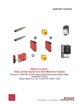
1
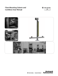
Safety Function: Two Hand Control
Products: 800Z Zero-Force Buttons
MSR125 Safety Relay / GSR SI Safety Relay
Safety Rating: PLe, Cat. 4 to EN ISO 13849.1 2008
Table of Contents
Introduction
3
Important User Information
3
Safety Function Realization: Risk Assessment
4
Two Hand Control Safety Function
4
Safety Function Requirements
4
General Safety Information
5
Functional Safety Description
6
Bill of Material
6
Setup and Wiring
7
System Overview
7
Electrical Schematic
8
Configuration
9
Calculation of the Performance Level
10
Verification and Validation Plan
13
Additional Resources
16
3
Introduction
This Safety Function application note explains how to wire and configure two 800Z
Zero-Force palm buttons, an MSR125 two hand control, an E-Stop, a GSR SI Safety Relay
and two 100S safety contactors to create a two hand control safety system. When the
operator places one hand on each button simultaneously (within 0.5 sec. of each other),
confirming that the operator is in the proper, safe location, the two 100s contactors are
energized powering the hazardous motion. Removing either or both hands will cause the
system to turn off the safety contactors.
The SISTEMA calculations in this document are for the system described here. A system
using different components or a different configuration would have to be calculated based
on its actual components and system structure.
Important User Information
Solid state equipment has operational characteristics differing from those of electromechanical
equipment. Safety Guidelines for the Application, Installation and Maintenance of Solid State
Controls (publication SGI-1.1 available from your local Rockwell Automation® sales office or online
at http://www.rockwellautomation.com/literature) describes some important differences between
solid state equipment and hard-wired electromechanical devices. Because of this difference,
and also because of the wide variety of uses for solid state equipment, all persons responsible
for applying this equipment must satisfy themselves that each intended application of this
equipment is acceptable.
In no event will Rockwell Automation, Inc. be responsible or liable for indirect or consequential
damages resulting from the use or application of this equipment.
The examples and diagrams in this manual are included solely for illustrative purposes. Because of the
many variables and requirements associated with any particular installation, Rockwell Automation, Inc.
cannot assume responsibility or liability for actual use based on the examples and diagrams.
No patent liability is assumed by Rockwell Automation, Inc. with respect to use of information,
circuits, equipment, or software described in this manual.
Reproduction of the contents of this manual, in whole or in part, without written permission of
Rockwell Automation, Inc., is prohibited.
4
Safety Function Realization: Risk Assessment
The required performance level is the result of a risk assessment and refers to the amount of the risk
reduction to be carried out by the safety-related parts of the control system. Part of the risk reduction
process is to determine the safety functions of the machine. For the purposes of this document the
assumed performance level required (PLr) is PLe, Category 4.
Two Hand Control Safety Function
The safety system described in this Safety Function application note contains two safety functions:
1. Two Hand Monitoring Safety Function: Power is provided to the hazard only when the operator’s
hands have been placed on the palm buttons simultaneously and remain on the buttons. Power is
removed when one or either hand is removed from its palm button.
2. E-Stop Safety Function: The removal of power from the hazard when the safety system detects
that the E-Stop has been actuated.
Safety Function Requirements
Two Hand Monitoring Safety Function: Controlled location of an operator’s hands during hazardous
motion by requiring the continuous actuation of two palm buttons to enable power to the motor.
Simultaneous operation of the two buttons must be within 0.5 seconds per ISO 13851. Upon
releasing either or both of the two palm buttons, power to the motor will be removed. Placing both
hands on the palm buttons simultaneously will restart the hazardous motion. Faults at the two-hand
palm buttons, wiring terminals or safety controller will be detected before the next safety demand.
The safe distance location of the two-hand control station must be established per ISO 13855 such
that the hazardous motion must be stopped before the operator can reach the hazard.
E-Stop Safety Function: Pressing the E-Stop will stop hazardous motion and prevent motion by
removal of power to the motor. Upon resetting the E-Stop pushbutton, hazardous motion and
power to the motor will not resume until a secondary action, pressing and releasing the reset button,
is performed. This Emergency Stop function is complementary to any other safeguards on the
machine and shall not reduce the performance of other safety related functions.
The safety functions in this example are each capable of connecting and interrupting power to
motors rated up to 9A, 600VAC. The safety functions will meet the requirements for Performance
Level “e”, Category 4 (PLe, Cat. 4), per ISO 13849-1, and SIL3 per IEC 62061, and control reliable
operation per ANSI B11.19. The stop implemented by each safety function is Stop Category 0.
5
Throughout this manual, when necessary, we use notes to make you aware of safety considerations.
General Safety Information
Contact Rockwell Automation to find out more about our safety risk assessment services.
6
Functional Safety Description
The purpose of the two hand monitoring safety function in this application note is to provide safe and
easy running and stopping of a hazardous machine to suit the requirements of a manufacturing process.
The machine is allowed to run, performing its task, when the operator is in a safe location with both the
operator’s hands are placed, on each of two palm buttons. When either one or both of the operator’s
hands are removed from a palm button, the MSR125 responds by opening its safety contacts and removes
power to the hazardous motion. This stops the machine and allows the operator to perform some safe task
in the guarded area while the machine is stopped and maintained stopped. Once this task is completed
the operator must move a distance away from the guarded area to access the two palm buttons. The
operator must place their hands on the two palm buttons, simultaneously. Responding to this, the MSR125
responds by closing its safety contacts. This starts the machine allowing it to perform its task.
The purpose of the E-Stop safety function is straightforward. When an urgent need to stop the machine
arises the E-Stop pushbutton is pressed. The GSR SI monitoring the E-Stop pushbutton responds by
opening its safety contacts removing power from the coils of the two 100S safety contactors. The 100s
contacts open removing power from the hazardous motion.
Bill of Material
Catalog Number
800Z-GL2Q5Y
800Z-G2AH1
889D-F5AC-2
440R-D23171
440R-A23209
800F-1YP3
800F-BX10
440R-S12R2
800FM-G611MX10
100S-C09EJ23C
Description
22.5 mm Type 4/4X/13 IP 66 Zero-Force Momentary General Purpose Touch Button, 10-40V
DC and 20-30V AC Input, Relay Output - 5-pin QD, Yellow Guard
Plastic Mounting Kit for 22.5 mm Holes, (GP)
5-pin Straight QD Cable, 22.5 mm Mounting Hole, 2 m (6.56 ft) Length
MSR125HP Relay Model, Two-hand Control, 2 N.O. Immediate Safety Outputs, N/A Auxiliary
Outputs, N/A Delayed Safety Outputs, 24V AC/DC Power Supply, Automatic/Manual Reset,
Removable Terminals
Bag of 4, 4-pin Screw Terminal Blocks
800F 1-hole Enclosure E-Stop Station, Plastic, PG, Twist-to-Release 40 mm, Non-illuminated,
2 N.C.
NO Status Contact (add to 800F-1YP3)
Guardmaster® Safety Relay, 1 Dual Channel Universal Input, 1 N.C. Solid State Auxiliary
Outputs
800F Push Button - Metal, Guarded, Blue, R, Metal Latch Mount, 1 N.O. Contact(s), 0 N.C.
Contact(s), Standard, Standard Pack (qty. 1)
MCS 100S-C Safety Contactor, 9 A, 24V DC
Quantity
2
Setup and Wiring
For detailed information on installing and wiring, refer to the product manuals listed in the
Additional Resources.
2
2
1
1
1
1
1
1
2
7
System Overview
The MSR125 relay model monitors the contacts of the two 800Z palm buttons. When the system is
running and one hand, or both hands, move from a palm button the MSR125 responds by opening
its safety contacts removing 24V from the coils of both 100S contactors. The contactors open their
contacts removing power from the hazardous motion. The hazardous motion coasts to a stop.
The MSR125 is wired automatic reset. As required by standards, the MSR125 will only reset if both
palm buttons are actuated by an operator’s hands within 0.5 seconds of each other (simultaneity).
When the standard’s simultaneity requirement is met the MSR125 closes its safety contacts provided
that two auxiliary contacts of the 100S contactors K1 and K2, wired in series between Y1 and Y2 of
the MSR125, are closed confirming that both 100Ss are properly de-energized. The closing safety
contacts energize the coils of the 100S contactors. The hazardous motion is restarted.
The MSR125 uses Plausibility check, e.g. use of normally open and normally closed mechanically
linked contacts to monitor the 800Z palm buttons for faults.
The GSR SI monitors the E-Stop push button. The pulsed outputs of the GSR SI (terminals S11 and S21) are
run separately through the two E-Stop contacts to input terminals S12 and S22 respectively. This enables
the GSR SI to detect loose wire, short to 24V, short to GND, welded contact and cross channel faults.
When the E-Stop push button is pressed the pulsed output to input circuits are broken. The GSR SI
responds by opening its safety contacts removing 24V from the coils of the 100S contactors.
De-energized, the 100Ss open their contacts. The hazardous motion coasts to a stop.
The GSR-S is configured for monitored manual reset. 24V is connected to the reset button via two
auxiliary NC contacts of the 100S contactors. The two closed NC contacts confirm that the 100S
contactors are properly de-energized. Once the E-Stop button is released and the reset pushbutton is
pressed for .250 to 3 seconds, then released, the GSR SI resets, closing its safety contacts. The hazardous
motion is restarted.
When the reset button is pressed for less than .250 seconds or longer than 3 seconds the reset signal is
ignored and the GSR SI safety contactors remain open. This is to prevent inadvertent reset and thwart tie
down of the reset button.
8
Electrical Schematic
24V
0V
MSR125
A1
Gry
A2
S11
Brn
Y1
K1
K2
800Z-LEFT
Y2
Blk
Blu
S13
Wht
S12
Brn
Gry
S21
800Z-RIGHT
Blu
Blk
S23
Wht
S22
13
14
23
24
A1
A2
Status
to PLC
SI
S11
S21
E-Stop
Status
to PLC
K1
K2
Reset 0
AM
MM
S12
Status
to PLC
Status
to PLC
S22
Reset
K1
Status
to PLC
Y32
13
K2
S34
14
Status
to PLC
A2
K1
23
MSR125 = 440R-D23171
SI = 440R-S12R2
A1
24
A1
A2
K2
L11
L1L2 L3
External Switched
Stop/Start Circuit
K1
K2
M
9
Configuration
10
Calculation of the Performance Level
The Performance Level required (PLr) for each safety function in this application note project is PLd,
Cat. 3. When configured correctly, the two safety functions project can achieve a safety rating of PLe,
Cat. 4 according to EN ISO 13849.1 2008.
The Functional Safety Specifications of the project call for a Performance Level on PLd (minimum)
and a structure of Cat 3 (minimum). A PFHd of less than 1.0 E-06 for the overall safety function is
required for PLd.
The overall Two Hand Control Safety Function value is shown below.
The Two Hand Control Safety Function can be modeled as follows:
11
The functional safety ratings for the 800Z INPUT subsystem are:
The functional safety ratings for the MSR125 LOGIC subsystem are:
The functional safety ratings for the 100S OUTPUT subsystem are:
The overall E-Stop safety function value is shown below.
12
The E-Stop safety function can be modeled as follows:
The functional safety ratings for the E-Stop INPUT subsystem are:
The functional safety ratings for the GSR SI LOGIC subsystem are:
13
The functional safety ratings for the 100S OUTPUT subsystem are:
Note that the 800Z palm buttons, E-Stop and Safety Contactors data includes MTTFd, DCavg, and
CCF data. This is because these are electromechanical devices. Electromechanical devices functional
safety evaluations include how frequently they are operated, whether they are effectively monitored
for faults and properly specified and installed.
SISTEMA calculates the MTTFd using B10d data provided for the contactors along with the estimated
frequency of use entered during the creation of the SISTEMA project. This application example
presumes that the E-Stop is operated or tested once per day ie 365 times per year.
The DCavg (99%) for the contactors was selected from the Output Device table of EN ISO 13849-1
Annex E. “Direct Monitoring”.
The DCavg (99%) for the E-Stop was selected from the Input Device table of EN ISO 13849-1 Annex E.
“Cross Monitoring”.
The (CCF) value is generated using the scoring process outlined in Annex F of ISO 13849-1.
The complete CCF scoring process must be done when actually implementing an application.
A minimum score of 65 points must be achieved. A CCF of 65 was entered for practical purposes in
each case for this application example.
Verification and Validation Plan
Verification and Validation play an important role in the avoidance of faults throughout the safety
system design and development process. ISO/EN 13849-2 sets the requirements for verification and
validation. It calls for a documented plan to confirm all the Safety Functional Requirements have
been met.
Verification is an analysis of the resulting safety control system. The Performance Level (PL) of the
safety control system is calculated to confirm it meets the Required Performance Level (PLr) specified.
The SISTEMA software tool is typically utilized to perform the calculations and assist with satisfying
the requirements of ISO 13849-1.
Validation is a functional test of the safety control system to demonstrate that it meets the specified
requirements of the safety function. The safety control system is tested to confirm all of the safety
related outputs respond appropriately to their corresponding safety related inputs. The functional
test should include normal operating conditions in addition to potential fault inject of failure modes.
A checklist is typically used to document the validation of the safety control system.
Prior to validating the GSR Safety Relay system, it is necessary to confirm the GSR Relay has
been wired and configured in accordance with the Installation Instructions.
14
Two Hand Control Station Safety Function Verification and Validation Checklist
General Machinery Information
Machine Name / Model Number
Machine Serial Number
Customer Name
Test Date
Tester Name(s)
Schematic Drawing Number
Guardmaster Safety Relay Model
Safety Wiring and Relay Configuration Verification
Test Step
Verification
Pass/Fail
Changes/Modifications
Visually inspect the safety relay circuit is wired as documented in the schematics.
Visually inspect the safety relay rotary switch settings are correct as documented.
Normal Operation Verification - The safety relay system properly responds to all normal Start, Stop, Estop and Reset Commands
Test Step
Verification
Pass/Fail
Changes/Modifications
Initiate a Start Command by simultaneously pressing both palm buttons. Both contactors should
energize for a normal machine run condition. Verify proper machine status indication and safety
relay LED indication.
Initiate a Stop Command by simultaneously releasing both palm buttons. Both contactors should
de-energize for a normal machine Stop condition. Verify proper machine status indication and safety
relay LED indication.
While Stopped, only press the left palm button. The door should remain closed and locked. Both
contactors should remain de-energized and open for a normal safe condition. Verify proper machine
status indication and safety relay LED indication. Repeat for right palm button.
Initiate Reset Command. Both contactors should remain de-energized. Verify proper machine status
indication and safety relay LED indication.
Abnormal Operation Verification - The Safety Relay system properly responds to all foreseeable faults with corresponding diagnostics.
Two Hand Run Station Input Tests
Test Step
Validation
Pass/Fail
Changes/Modifications
Pass/Fail
Changes/Modifications
Pass/Fail
Changes/Modifications
While Stopped, press the left palm button followed by the right 1 sec. later. Both contactors should
remain de-energized and open. Verify proper machine status indication and safety relay LED indication.
Repeat for sequence starting with the right palm button.
While Running, remove the Channel 1 wire from the E-Stop pushbutton. Both contactors
should de-energize. Verify proper machine status indication and safety relay LED indication.
Repeat for Channel 2.
While Running, short Channel 1 of the safety relay to +24V DC. Both contactors should de-energize.
Verify proper machine status indication and safety relay LED indication. Repeat for Channel 2.
While Running, short Channel 1 of the safety relay to (-) 0V DC. Both contactors should de-energize.
Verify proper machine status indication and safety relay LED indication. Repeat for Channel 2.
While Running, short Channels 1 & 2 of the safety relay. Both contactors should de-energize.
Verify proper machine status indication and safety relay LED indication.
GSR Logic Solver Tests
Test Step
Validation
While Running, remove the single wire safety connection between two adjoining safety relays in the
system. All contactors should de-energize. Verify proper machine status indication and safety relay LED
indication. Repeat for all safety connections. This test is not applicable for single relay circuits.
While Running, turn the logic rotary switch on the safety relay. All contactors should remain
de-energized. Verify proper machine status indication and safety relay LED indication. Repeat for all
safety relays in the system.
Safety Contactor Output Tests
Test Step
Validation
While Running, remove the contactor feedback from the safety relay. All contactors should remain
energized. Initiate a Stop Command followed by a Reset Command. The relay should not restart or reset.
Verify proper machine status indication and safety relay LED indication.
15
GSR Emergency Stop Safety Function Verification and Validation Checklist
General Machinery Information
Machine Name / Model Number
Machine Serial Number
Customer Name
Test Date
Tester Name(s)
Schematic Drawing Number
Guardmaster Safety Relay Model
Safety Wiring and Relay Configuration Verification
Test Step
Verification
Pass/Fail
Changes/Modifications
Visually inspect the safety relay circuit is wired as documented in the schematics.
Visually inspect the safety relay rotary switch settings are correct as documented.
Normal Operation Verification - The safety relay system properly responds to all normal Start, Stop, Estop and Reset Commands
Test Step
Verification
Pass/Fail
Changes/Modifications
Initiate a Start Command. Both contactors should energize for a normal machine run condition.
Verify proper machine status indication and safety relay LED indication.
Initiate a Stop Command. Both contactors should de-energize for a normal machine Stop condition.
Verify proper machine status indication and safety relay LED indication.
While Running, press the E-Stop pushbutton. Both contactors should de-energize and open for a normal
safe condition. Verify proper machine status indication and safety relay LED indication. Repeat for all
E-Stop pushbuttons.
While Stopped, press the E-Stop pushbutton, initiate a Start Command. Both contactors should remain
de-energized and open for a normal safe condition. Verify proper machine status indication and safety
relay LED indication. Repeat for all E-Stop pushbuttons.
Initiate Reset Command. Both contactors should remain de-energized. Verify proper machine status
indication and safety relay LED indication.
Abnormal Operation Verification - The Safety Relay system properly responds to all foreseeable faults with corresponding diagnostics.
E-Stop Input Tests
Test Step
Validation
Pass/Fail
Changes/Modifications
Pass/Fail
Changes/Modifications
Pass/Fail
Changes/Modifications
While Running, remove the Channel 1 wire from the safety relay. Both contactors should de-energize.
Verify proper machine status indication and safety relay LED indication. Repeat for Channel 2.
While Running, short the Channel 1 of the safety relay to +24V DC. Both contactors should de-energize.
Verify proper machine status indication and safety relay LED indication. Repeat for Channel 2.
While Running, short the Channel 1 of the safety relay to (-) 0V DC. Both contactors should de-energize.
Verify proper machine status indication and safety relay LED indication. Repeat for Channel 2.
While Running, short Channels 1 & 2 of the safety relay. Both contactors should de-energize.
Verify proper machine status indication and safety relay LED indication.
GSR Logic Solver Tests
Test Step
Validation
While Running, remove the single wire safety connection between two adjoining safety relays in the
system. All contactors should de-energize. Verify proper machine status indication and safety relay LED
indication. Repeat for all safety connections. This test is not applicable for single relay circuits.
While Running, turn the logic rotary switch on the safety relay. All contactors should remain
de-energized. Verify proper machine status indication and safety relay LED indication. Repeat for all
safety relays in the system.
Safety Contactor Output Tests
Test Step
Validation
While Running, remove the contactor feedback from the safety relay. All contactors should remain
energized. Initiate a Stop Command followed by a Reset Command. The relay should not restart or reset.
Verify proper machine status indication and safety relay LED indication.
16
Additional Resources
For more information about the products used in this example refer to these resources.
Document
Pub. No.
Description
Guard Locking Switch Installation Instructions
440G-IN007
How to install, commission, operate and maintain the 440G-TZS21UPRH
Guardmaster Safety Relay Installation Instructions
10000175129
How to install, commission, operate and maintain the 440R-D22R2 Safety Relays
Guardmaster Safety Relay Troubleshooting Guide
440R-TG002
How to troubleshoot the 440RD22R2 Safety Relays
Guardmaster Expansion Relay Installation Instructions
440R-IN045
How to install, commission, operate and maintain the 440R-EM4R2D Expansion Relay
Guardmaster Expansion Relay Troubleshooting Guide
440R-TG001
How to install, commission, operate and maintain the 440R-EM4R2D Expansion Relay
Safety Products Catalog
S117-CA001A
Overview of Safety products, product specifications, and application examples
GuardShield Type 4 User Manual
440L-UM003
How to install, operate, and maintain the 440L Safety Light Curtains
Next Generation Guardmaster Safety Relays
SAFETY-WD001 Functional descriptions, guidance, and wiring for Safety Relays
Heavy Duty Guard Interlock Switch Installation
Instructions
440K-IN008
How to install, configure, commission, operate, and maintain MT-GD2 Interlock Switches
Trojan T15 Interlock Switch Installation Instructions
440K-IN003
How to install, configure, commission, operate, and maintain Trojan T15 Interlock Switches
Safety Interlock Switches Brochure
EUSAFE-BR001
Overview of Interlock Switches
Guardmaster Safety Relay SI Installation Instructions
440R-IN042
How to install, configure, commission, operate, and maintain GSR SI Safety Relays
Guardmaster Safety Relays Selection Guide
440R-SG001
Overview of Guardmaster Safety Relays
RightSight Photoelectric Sensor Installation Instructions
42EF-IN003
How to install, commission, operate, and maintain 42EF Photoelectric Sensors
MSR42 Control Module User Manual
440R-UM008
How to install, commission, operate, and maintain MSR42 Systems
MSR45E Safety Relay Expansion Module User Manual
440R-UM007
How to install, commission, operate, and maintain the MSR45E Expansion Module
SensaGuard Integrated Latch Unique Coded Installation
Instructions
440N-IN011
How to install, commission, operate, and maintain the SensaGuard
Touch Button and Guard Installation Instructions
Zero-Force Touch Buttons Family Brochure
MSR12T Safety Relays Installation Instructions
Guardmaster Safety Relay Installation Instructions
800Z-IN001-MU How to install and mount the 800Z Touch Button
800Z-BR002
MINOTR-IN010
440R-IN042
Brochure that describes all 800Z Palm Buttons
How to install, configure, commission, operate, and maintain the MSR 12T Safety Relays
How to install, commission, operate and maintain the 440R-S12R2 Safety Relays
You can view or download publications at http://www.rockwellautomation.com/literature. To order paper copies of technical
documentation, contact your local Allen-Bradley® distributor or Rockwell Automation sales representative.
For More Information on
Safety Function Capabilities, visit:
discover.rockwellautomation.com/safety
Rockwell Automation, Allen-Bradley, GuardMaster, GuardShield, PHOTOSWITCH, RightSight, and SensaGuard are trademarks of Rockwell Automation, Inc.
Trademarks not belonging to Rockwell Automation are property of their respective companies.
Publication SAFETY-AT071C-EN-E – May 2013
Supersedes Publication SAFETY-AT071B-EN-E – January 2013
Copyright ©2013 Rockwell Automation, Inc. All Rights Reserved.