1
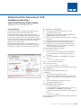
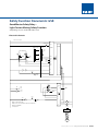
NHP SAFETY REFERENCE GUIDE
GSR
SAFETY FUNCTION
DOCUMENTS
Light Curtain
with Muting
Safety Function Documents: GSR
GuardMaster Safety Relay –
Light Curtain Muting Safety Function
Safety Rating: PLe, Cat. 4 to EN ISO 13849.1 2008
Table of Contents:
Introduction
4-97
Important User Information
4-97
Safety Function Realization: Risk Assessment
4-98
Light Curtain Muting Safety Function
4-98
Safety Function Requirements
4-98
General Safety Information
5-99
Functional Safety Description
6-100
Bill of Material
6-101
Setup and Wiring
6-101
System Overview
6-102
Electrical Schematic
6-103
Configuration
6-104
Configure the GSR SI Safety Relay for Monitored Manual Reset
6-104
Configure the MSR42 Relay
6-105
Calculation of the Performance Level
6-110
Verification and Validation Plan
6-115
Additional Resources
6-119
NHP Safety Reference Guide > Safety Function Documents: GSR
6B-102
Safety Function Documents: GSR
GuardMaster Safety Relay –
Light Curtain Muting Safety Function
Safety Rating: PLe, Cat. 4 to EN ISO 13849.1 2008
Introduction
Important User Information
This safety function application technique explains how to
wire, configure, and integrate an MSR42 safety relay and an
MSR45E expansion module with a GSR SI safety relay to monitor
a 440L GuardShield™ light curtain to create a 2 Sensor L-type
muting (single direction muting) system with an additional
E-stop function. When an object interrupts the light curtain
field of view, when it is not muted, or a fault is detected in
the monitoring circuit, the MSR42 relay and MSR45E module
de-energizes the redundant pair of 100S contactors, stopping
the motion. Whenever the E-stop is pressed the GSR SI relay deenergizes the contactors, stopping the motion.
Solid state equipment has operational characteristics differing
from those of electromechanical equipment. Safety Guidelines
for the Application, Installation and Maintenance of Solid State
Controls (publication SGI-1.1 available from your local Rockwell
Automation® sales office or online
at http://www.rockwellautomation.com/literature) describes
some important differences between
solid state equipment and hard-wired electromechanical
devices. Because of this difference,
and also because of the wide variety of uses for solid state
equipment, all persons responsible
for applying this equipment must satisfy themselves that each
intended application of this equipment is acceptable.
When an object of the specified size passes the muting sensors
in the proper sequence within the configured time interval, the
light curtain is muted. The object is allowed to continue passing
through the light curtain without the motion being stopped.
Muting is terminated as soon as the object leaves the light
curtain’s field of view.
A mute dependant override capability is provided to clear
objects stranded in the monitored area.
When an object interrupts the light curtain’s field of view from
the ‘non-muted’ direction, the MSR42 relay and MSR45E module
de-energize the contactors. When an object approaches from
the ‘muted’ direction and does not pass the muting sensors in
the proper sequence or within the configured time interval,
muting is not activated. In this case, the contactors are deenergized as soon as the object interrupts the light curtain’s
field of view.
In no event is Rockwell Automation, Inc., responsible or liable
for indirect or consequential damages resulting from the use or
application of this equipment.
The examples and diagrams in this manual are included
solely for illustrative purposes. Because of the many variables
and requirements associated with any particular installation,
Rockwell Automation, Inc., cannot assume responsibility or
liability for actual use based on the examples and diagrams.
No patent liability is assumed by Rockwell Automation, Inc., with
respect to use of information, circuits, equipment, or software
described in this manual.
Reproduction of the contents of this manual, in whole or in part,
without written permission of Rockwell Automation, Inc., is
prohibited.
NHP Safety Reference Guide > Safety Function Documents: GSR
6B-103
Safety Function Documents: GSR
GuardMaster Safety Relay –
Light Curtain Muting Safety Function
Safety Rating: PLe, Cat. 4 to EN ISO 13849.1 2008
Safety Function Realization: Risk Assessment
Safety Function Requirements
The performance level required is the result of a risk assessment
and refers to the amount of the risk reduction to be carried out
by the safety-related parts of the control system. Part of the risk
reduction process is to determine the safety functions of the
machine. In this application, the performance level required (PLr)
by the risk assessment is Category 3, Performance Level d (CAT. 3,
PLd), for each safety function. A safety system that achieves CAT.
3, PLd or higher can be considered control reliable. Each safety
product has its own rating and can be combined to create a safety
function that meets or exceeds the PLr.
Interrupting the light curtain stops and prevents hazardous
motion by removing power to the motor. The motor coasts
to a stop (Stop Category 0). Upon resetting the light curtain,
hazardous motion and power to the motor does not resume until
a secondary action (start button depressed) occurs. Muting the
light curtain is done to allow automatically-fed material to enter
the area. Multiple sensors are configured to detect the incoming
material, and initiate and monitor the muting function per IEC/
TS 62046. Faults at the light curtain, muting sensors, wiring
terminals or safety controller are detected before the next safety
demand. The safe distance from the location of the light curtain
to the hazard must be established per ISO 13855 so the hazardous
motion is stopped before the user can reach the hazard. The safety
function in this example is capable of connecting and interrupting
power to motors rated up to 9 A, 600V AC.
From: Risk Assessment (ISO 12100)
1
Identification of safety functions
2
Specification of characteristics of each safety function
3
Determination of required PL (PLr) of each safety function
The safety function in this application technique meets or exceeds
the requirements for Category 3, Performance Level “d” (CAT. 3,
PLd), per EN ISO 13849-1 and control reliable operation per ANSI
B11.19. Throughout this manual, when necessary, we use notes to
make you aware of safety considerations.
To: Realization and PL evaluation
Light Curtain Muting Safety Function
This application includes three safety functions:
1.Emergency stop of hazardous motion initiated by a light
curtain.
2.Muting of a light curtain.
3.Emergency stop of hazardous motion initiated by an E-stop
button.
This system executes a Stop Category 0 stop. The motion is
allowed to coast to a stop.
NHP Safety Reference Guide > Safety Function Documents: GSR
6B-104
Safety Function Documents: GSR
GuardMaster Safety Relay –
Light Curtain Muting Safety Function
Safety Rating: PLe, Cat. 4 to EN ISO 13849.1 2008
General Safety Information
WARNING: Identifies information about practices or circumstances that can
cause an explosion in a hazardous environment, which can lead to personal
injury or death, property damage, or economic loss.
Identifies information that is critical for successful application and understanding of the product.
ATTENTION: Identifies information about practices or circumstances that
can lead to personal injury or death, property damage, or economic loss.
Attentions help you identify a hazard, avoid a hazard, and recognize the
consequence.
SHOCK HAZARD: Labels typically found on or inside equipment (for
example, a drive or motor) to alert people that dangerous voltage can be
present.
BURN HAZARD: Labels typically found on or inside equipment (for
example, a drive or motor) to alert people that surfaces can reach dangerous
temperatures.
Contact Rockwell Automation to find out more about our safety risk assessment services.
This application example is for advanced users and assumes that you are
trained and experienced in safety system requirements.
ATTENTION: Perform a risk assessment to verify that all task and hazard conditions have been identified and addressed. The risk assessment can require
additional circuitry to reduce the risk to a tolerable level. Safety circuits must
consider safety distance calculations that are not part of the scope of this
document.
NHP Safety Reference Guide > Safety Function Documents: GSR
6B-105
Safety Function Documents: GSR
GuardMaster Safety Relay –
Light Curtain Muting Safety Function
Safety Rating: PLe, Cat. 4 to EN ISO 13849.1 2008
Functional Safety Description
Hazardous motion is stopped or prevented by interrupting the
field of view of the light curtain
or by errors in the muting sequence or timing. The 440L light
curtain and two RightSight muting sensors are connected to
the MSR42 safety relay. The MSR42 relay is mated to an MSR45E
expansion module, which provides two NO safety contacts
that control power to the 100S contactor coils via the GSR SI
safety contacts. Whenever the MSR42/MSR45E opens the safety
contacts, the hazardous motion is stopped. When all safety
input signals are correct, no faults are detected, and the reset
push button is pressed, the MSR42 energizes its safety contacts
to provide power to the contactor coils via the GSR SI.
The E-stop is connected to the GSR SI, which uses pulse
checking to monitor the E-stop for actuation and faults.
Whenever the E-stop is actuated, the GSR SI opens its safety
contacts and the hazardous motion is stopped. When all safety
input signals are correct, no faults are detected, and the reset
push button is pressed (for 0.25 to 3.0 seconds) and then
released, the GSR SI re-energizes its safety contacts to provide
power to the contactor coils.
In summary, when the un-muted light curtain is blocked,
the contactors drop out. When the light curtain is unblocked
and the appropriate reset button is pressed and released, the
contactors are energized.
When properly muted, the light curtain’s field of view can
be interrupted without dropping out the safety contactors.
Whenever the light curtain is muted, the muting lamp is
energized.
Bill of Material
Cat. No.
440L-P4KL1280YD
Description
Qty
GuardShield™ Safety Light Curtain, Res 30 mm, Pt Ht 1280 mm, 64 Beams, Integrated Laser Alignment
1
2
60-2649
92-89
DC Micro (M12), Female, Straight, 4-pin, PVC Cable, Yellow, Unshielded, 22 AWG, IEC Color Coded,
No Connector, 2 m (6.56 ft) length
DC Micro (M12), Female, Straight, 8-pin, PVC Cable, Yellow, Unshielded, 24 AWG, IEC Color Coded,
No Connector, 2 m (6.56 ft) length
PHOTOSWITCH® Photoelectric Sensor, RightSight, Polarized Retroflective, Red, DC - 2 Complementary
LO/DO Outputs, Source (PNP), 4-pin DC Micro QD on 152 mm (6 in.) pigtail
DC Micro (M12), Female, Straight, 4-pin, PVC Cable, Yellow, Unshielded, 22 AWG, IEC Color Coded,
No Connector, 2 m (6.56 ft) length
60-2649 Swivel/Tilt Mounting Bracket
92-89 Reflector
440R-P226AGS-NNR
MSR42 Multi-function Controller for GuardShield Light Curtains
1
889D-F4AC-2
889D-F8AB-2
42EF-P2MPB-F4
889D-F4AC-2
855EP-G24L5
445L-AF6150
440R-ACABL1
Control Tower Stack Light, Pre-assembled, 10 cm Pole Mount with Cap, Gray Housing, 24V AC/DC Full
Voltage, Amber Flashing LED
Optical Interface Tool (required to configure the MSR42)
1
1
2
2
2
1
1
Ribbon cable 10-pin for 1 extension
MSR45E - Relay Extension (ribbon cables for 1, 2 or 3 MSR45 extension are ordered separately from
the MSR45)
1
800F-1YP3
800F 1-hole Enclosure E-stop Station, Plastic, PG, Twist-to-release 40 mm, Non-illuminated, 2 N.C.
1
800F-BX10
N.O. Status Contact (add to 800F-1YP3)
1
440R-S12R2
Guardmaster Safety Relay, 1 Dual Channel Universal Input, 1 N.C. Solid State Auxiliary Outputs
1
800FM-G611MX10
800F Push Button - Metal, Guarded, Blue, R, Metal Latch Mount, 1 N.O. Contact(s), 0 N.C. Contact(s),
standard, standard pack (qty. 1)
1
100S-C09EJ23C
MCS 100S-C Safety Contactor, 9 A, 24V DC
2
440R-P4NANS
1
NHP Safety Reference Guide > Safety Function Documents: GSR
6B-106
Safety Function Documents: GSR
GuardMaster Safety Relay –
Light Curtain Muting Safety Function
Safety Rating: PLe, Cat. 4 to EN ISO 13849.1 2008
Setup and Wiring
Ds = K x (Ts + Tc + Tr – Tbm) + Dpf.
For detailed information on installing and wiring, refer to the
product manuals listed in the Additional Resources.
K:
the ‘standard’ hand speed of 63 inches per second
Ts:
the stop time of the machine
A safety light curtain provides no physical barrier between a
person and the hazardous motion. The safety light curtain must
be installed at a sufficient distance from the hazardous motion
to ensure that someone putting a hand through the light curtain
cannot reach the hazard before it has stopped. This distance is
referred to as the Safety Distance.
Tc:the response time of the safety system; the MSR42 relay,
MSR45E module, and K1/K2 contactors
The Safety Distance (Ds) required varies from installation to
installation and, therefore, must be calculated for each specific
application. This application technique uses the ANSI formula:
Dpf:the distance that a ‘standard’ hand could possibly move
through the LC before it is detected. This is a fixed value
based on the light curtain resolution
Tr:the response time of the presence sensing device; the light
curtain (LC)
Tbm:additional time allowed for the brake monitor (if any) to
compensate for variations in normal stopping time
In this application technique, the values are:
K:
63 inches per second
Ts:500 ms – (0.5 sec.) is only for purposes of this application
note. The stop time for a specific application must be
measured
Tc:
39 ms = 18 ms (MSR42) + 6 ms (MSR45E) + 15 ms (K1/K2)
Tr:
20 ms = LC
Tr + Tc = 20 + 39 = 59 ms = 0.059 sec.
Tbm: 0 – none used in this application
Dpf: 78.7 mm (3.1 inches)
DS = (63 x 0.5 + 0.059]) + 3.1 = 38.3 inches
The LC must not be mounted closer than 895 mm (35.24 in.) from
the guarded hazard.
The following is the same calculation using 13855:
S = (K x T) + C
S: minimum distance in millimeters (mm)
K:is a parameter, in millimeters per second (mm/s), derived
from data on approach speeds of the body or parts of the
body
T: is the overall stopping performance in seconds
C: is the intrusion distance in mm
In this application technique, the values are:
K = 1600 mm per second
T = 559 ms (Machine Stopping Time 500 ms + 20 ms [LC] +
18 ms [MSR42] + 6 ms [MSR45E] + 15 ms [K1/K2])
C = 8(d - 14) but not less than 0 where ‘d’ is the resolution of
the LC
S = 1600 x .559 + 8(14 - 14)
The LC must not be mounted closer than 895 mm (35.24 in.) from
the guarded hazard.
NHP Safety Reference Guide > Safety Function Documents: GSR
6B-107
Safety Function Documents: GSR
GuardMaster Safety Relay –
Light Curtain Muting Safety Function
Safety Rating: PLe, Cat. 4 to EN ISO 13849.1 2008
The MSR42 Configuration Software can also be used to calculate
safety distances.
System Overview
A 2 Sensor L-type muting (single direction muting) system allows
loads or objects to pass through its light curtains in one direction
without shutting down the protected machine or process but
will stop the protected machine or process if anything or anyone
attempts to move past the light curtains in the other direction.
The system will also shut down the protected machine when an
object fails to satisfy the requirements for muting. 2 Sensor L-type
muting is often used to guard the output area of a machine or
process. Typical places where this form of muting would be typical
are the exit of an automatic palletizing system or an automatic
assembly machine.
To initiate muting an object must pass, in sequence, sensor 1, then
sensor 2 and finally, the light curtain. The time between the beam
breaks is monitored and must not exceed the specified times. The
overall time that the system is muted is likewise monitored. The
protected system shuts down if any specified time is exceeded.
The sensors and light curtain must be positioned so that all three
are broken simultaneously at one point in the process. The sensors
and light curtain must be restored in the same sequence as they
were passed to initiate the muting sequence. A new object cannot
start the process (break sensor 1) until the previous object has
moved beyond the light curtain. The protected system shuts
down if either sensor is broken before the previous object has
moved beyond the light curtain. Muting is suspended as the
object passes out of the light curtain field of view.
The MSR42 relay monitors the 100S contactors via NC contacts
from each contactor connected in series to provide a Start Release
function. The MSR42 relay does not respond to its Start button
and energize the MSR45E safety contacts when the light curtain is
interrupted, there is a fault detected, or when the 100S contactors
are not in the proper off state. The MSR42 runs and monitors
a muting lamp. Should the lamp burn out or be removed, the
MSR42 relay does not mute the light curtain.
The GSR SI relay monitors the state of the E-stop push button.
It checks for faults by connecting its pulse test outputs though
the E-stop contacts and monitoring its inputs. The GSR SI relay
monitors itself for internal faults. A fault in the E-stop circuit, an
internal fault, or pressing the E-stop causes the GSR SI relay to
open its safety contacts, shutting down the protected system.
The GSR relay monitors the 100S contactors via NC contacts from
each contactor connected in series as part of its reset circuit. The
GSR SI relay does not respond to its reset button and energize its
safety contacts when the E-stop button has not been released,
a fault is detected, or when the 100S contactors are not in the
proper off state.
The 440L light curtain monitors itself and its outputs for faults
and responds to any fault by turning off both of its outputs. The
MSR42 relay monitors the light curtain outputs and the sensor
outputs. The MSR42 relay verifies that it receives the sensors and
light curtain signals in the proper sequence within the specified
times. When the MSR42 relay detects any fault at its inputs or an
internal fault, it de-energizes the MSR45E safety contacts, shutting
down the protected system.
NHP Safety Reference Guide > Safety Function Documents: GSR
6B-108
Safety Function Documents: GSR
GuardMaster Safety Relay –
Light Curtain Muting Safety Function
Safety Rating: PLe, Cat. 4 to EN ISO 13849.1 2008
Electrical Schematic
24V*
0V*
* Class 2 Source required
+24V
0V
855EP-G24L5
Lamp
A
440L-P4KL1280YD
Brn
Transmitter
to PLC
S2
Wht
Status
to PLC
Grn
Wht
Pnk
Status
to PLC
Blu
Blu
Blu
Blu
Blk
*
GPIO4
Gry
Brn
Brn
MSR45E
MSR42
Receiver
Wht Status
42EF-P2MPB-F4 (2)
S1
Brn
GPIO3
Status
to PLC
Status
to PLC
Info1
Info2
GPIO2
Blk
GPIO1
13
14
K1
K2
IN2
23
Start
Status
to PLC
24
IN1
A1
A2
E-Stop
K1
K2
SI
Status
to PLC
S11
Y32
S21
Status
to PLC
Status
to PLC
Status
to PLC
Reset 0
AM
MM
S12
Reset
K1
S22
K2
Status
to PLC
S34
13
14
MSR42 = 440R-P226AGS-NNR
*Ribbon Cable connector MSR42 to MSR 45E = 440R-ACABL1
MSR45E = 440R-P4NANS
SI = 440R-S12R2
A1
K1
A2
A1
K2
A2
23
24
L11
L1 L2 L3
External Switched
Stop/Start Circuit
K1
K2
M
NHP Safety Reference Guide > Safety Function Documents: GSR
6B-109
Safety Function Documents: GSR
GuardMaster Safety Relay –
Light Curtain Muting Safety Function
Safety Rating: PLe, Cat. 4 to EN ISO 13849.1 2008
Configuration
The 440L light curtain features DIP switches to configure it for different applications.
This application uses the default settings so no DIP switch changes are necessary.
Receiver - Factory Settings
Switch
1
Switch Function
Default Setting
Description
ON
2
Mode Activation - Combination activates one of the
following modes: Guard Only, Start Interlock,
Restart Interlock
ON
3
MPCE: Monitoring Disable
ON
Disabled
4
Fixed Blanking Activate
OFF
Disabled
5
Floating Blanking Activate - Single Beam
OFF
6
Floating Blanking Activate - Two Beams
OFF
7
Set Beam Coding
OFF
8
Not Used
OFF
Guard Only
Switches 5&6 cannot be activated “On” at the same time
Disabled
Transmitter - Factory Settings
Switch
Switch Function
Default Setting
1
Set Beam Coding
OFF
2
Machine Test Signal
OFF
Description
Disabled
OFF: Signal High Active–No connection or connect normally open
ON: Signal Low Active–Connect N/C
0
Configure the GSR SI Safety Relay for Monitored Manual Reset
AM
The following procedure sets the function of the drive:
1.Start configuration/overwrite: With power off, turn the rotary switch to position “0” and unit
is powered up. After power-up test, the PWR status indicator flashes red.
MM
2.Set configuration: Turn the rotary switch to the desired position. The IN1 status indicator
blinks the new setting. NOTE: Position is set when PWR status indicator is solid green.
0
3.Lock in configuration by cycling unit power.
4.Configuration must be confirmed before operation. A white space on the face of the device
is provided to record unit setting.
AM
MM
NHP Safety Reference Guide > Safety Function Documents: GSR
6B-110
Safety Function Documents: GSR
GuardMaster Safety Relay –
Light Curtain Muting Safety Function
Safety Rating: PLe, Cat. 4 to EN ISO 13849.1 2008
Configure the MSR42 Relay
Follow these steps to configure the MSR42 relay.
4.From the GPIO pull-down menu, choose Muting other device
(OSSDs).
1.Open the MSR42 configuration software.
Refer to Configuring GSR SI Safety Relay for Monitored Manual
Reset, publication SAFETY-UM001.
5. A safety notice appears. Click OK to continue.
2. On the software home screen, click MSR42.
6. The Muting screen appears. Click the 2 sensor L-type tab.
3. On the MSR42 configuration screen, click the Configuration tab.
NHP Safety Reference Guide > Safety Function Documents: GSR
6B-111
Safety Function Documents: GSR
GuardMaster Safety Relay –
Light Curtain Muting Safety Function
Safety Rating: PLe, Cat. 4 to EN ISO 13849.1 2008
Configure the MSR42 Relay (cont)
7. In the Time Settings area, set the following:
t(sens) [s] to 3.6 seconds.
t(espe) [s] to 3 seconds.
t(mute) [min] to 3 minutes.
t(mdo) [s] to 30 seconds.
Leave t(msdel) [s] set at 0.050.
TIP: Click the question mark box in the Time Settings area for an explanation of each time setting.
8.Click OK to save your changes and return to the MSR42 configuration screen.
NHP Safety Reference Guide > Safety Function Documents: GSR
6B-112
Safety Function Documents: GSR
GuardMaster Safety Relay –
Light Curtain Muting Safety Function
Safety Rating: PLe, Cat. 4 to EN ISO 13849.1 2008
Configure the MSR42 Relay (cont)
9.On the Configuration tab, set the following:
From the IN1 pull-down menu, choose Start.
From the IN2 pull-down menu, choose Start Release.
Notice that the design error messages data field now says Design OK.
10. From the File menu, choose Configuration control document.
NHP Safety Reference Guide > Safety Function Documents: GSR
6B-113
Safety Function Documents: GSR
GuardMaster Safety Relay –
Light Curtain Muting Safety Function
Safety Rating: PLe, Cat. 4 to EN ISO 13849.1 2008
Configure the MSR42 Relay (cont)
Notice that the document includes the times set in step 7 and response times used in the Safety Distance
calculation on page 7.
11. Click Print to include this information as part of the system documentation.
Refer to Configuring GSR SI Safety Relay for Monitored Manual Reset, publication SAFETY-UM001, for how
to connect the optical interface between your personal computer (PC) and the MSR42 relay so you can
download the created configuration to the MSR42 relay.
12.The download sequence requires you to enter the MSR device number.
The serial number can be found on the side of the MSR42.
NHP Safety Reference Guide > Safety Function Documents: GSR
6B-114
Safety Function Documents: GSR
GuardMaster Safety Relay –
Light Curtain Muting Safety Function
Safety Rating: PLe, Cat. 4 to EN ISO 13849.1 2008
Configure the MSR42 Relay (cont)
13. When communication is established, choose File > PC -> MSR42 (Download).
14. For the password, type ABGM (all CAPITAL letters) and click OK.
The download proceeds.
NHP Safety Reference Guide > Safety Function Documents: GSR
6B-115
Safety Function Documents: GSR
GuardMaster Safety Relay –
Light Curtain Muting Safety Function
Safety Rating: PLe, Cat. 4 to EN ISO 13849.1 2008
Calculation of the Performance Level
The project’s functional safety specifications call for a structure of Cat 3 (minimum) and a PLr of PLd
(minimum). A PFHd of less than 1.0 E-06 for the overall safety function is required for PLd.
This SISTEMA project includes three safety functions.
1.Emergency stop of hazardous motion initiated by a light curtain.
2.Muting of a light curtain.
3.Emergency stop of hazardous motion initiated by an E-stop button.
The individual safety function’s achieved performance level (PL) values are shown below.
In this system, the PL achieved by each safety function is higher than the PLr required (PLd per EN ISO
13849-1:2008) by the risk assessment.
Electromechanical devices, like E-stop buttons and safety contactors, have limited operational lives
directly related to how often they are operated. In the following calculations, it is presumed that:
The E-stop button is operated 730 (365 X 2) times a year.
Safety contactors operate a total of 8,760 (24 X 365) times a year.1
All other components are electronic and thus have an essentially infinite operational life.
The emergency stop of hazardous motion initiated by a light curtain’s safety function can be modeled
as below.
INPUT
LOGIC
OUTPUT
100S
K1
Light Curtain
Safety Function
Light
Curtain
MSR42
MSR45E
100S
K2
Subsystem 1
Subsystem 2
Subsystem 3
Subsystem 4
NHP Safety
Reference Guide > Safety Function Documents: GSR 6B-116
Applies to safety contactors where their operation can be the result of power up/reset, an E-stop
being
pressed, the light curtain’s field of view being interrupted, or an error in the muting process.
1
Safety Function Documents: GSR
GuardMaster Safety Relay –
Light Curtain Muting Safety Function
Safety Rating: PLe, Cat. 4 to EN ISO 13849.1 2008
Calculation of the Performance Level (cont)
The functional safety data for the emergency stop of hazardous motion initiated by a light curtain’s
safety function is as follows.
The functional safety data for the light curtain’s subsystem is as follows.
The functional safety data for the MSR42 relay’s logic subsystem is as follows.
The functional safety data for the MSR45E relay’s logic subsystem is as follows.
The functional safety data for the 100S contactor’s output subsystem is as follows.
NHP Safety Reference Guide > Safety Function Documents: GSR
6B-117
Safety Function Documents: GSR
GuardMaster Safety Relay –
Light Curtain Muting Safety Function
Safety Rating: PLe, Cat. 4 to EN ISO 13849.1 2008
Calculation of the Performance Level (cont)
The muting of a LC’s safety function can be modeled as follows.
INPUT
LOGIC
OUTPUT
100S
K1
Sensor
Block
MSR42
Muted Light Curtain
Safety Function
MSR45E
Light
Curtain
Block
Subsystem 1
100S
K2
Subsystem 2
Subsystem 3
Subsystem 4
The functional safety data for the muting of a LC’s safety function is as follows.
The functional safety data for the muting sensors’ input subsystem is as follows.
The functional safety data for the light curtain’s input subsystem is as follows.
The functional safety data for the MSR42 relay’s logic subsystem is as follows.
NHP Safety Reference Guide > Safety Function Documents: GSR
6B-118
Safety Function Documents: GSR
GuardMaster Safety Relay –
Light Curtain Muting Safety Function
Safety Rating: PLe, Cat. 4 to EN ISO 13849.1 2008
Calculation of the Performance Level (cont)
The functional safety data for the MSR45E relay’s logic subsystem is as follows.
The functional safety data for the 100S contactor’s output subsystem is as follows.
Emergency stop of hazardous motion initiated by an E-stop button can be modeled as follows.
INPUT
LOGIC
100S
K1
E-Stop 1
B1/E1
E-Stop
Safety Function
OUTPUT
GSR SI
E-Stop 1
B2/E2
Sub-system 1
100S
K2
Sub-system 2
Sub-system 3
The functional safety data for the emergency stop of hazardous motion initiated by an E-stop button safety
function is as follows.
NHP Safety Reference Guide > Safety Function Documents: GSR
6B-119
Safety Function Documents: GSR
GuardMaster Safety Relay –
Light Curtain Muting Safety Function
Safety Rating: PLe, Cat. 4 to EN ISO 13849.1 2008
Calculation of the Performance Level (cont)
The functional safety data for the E-stop button’s input subsystem is as follows.
The functional safety data for the GSR SI logic subsystem is as follows.
The functional safety data for the 100S safety contactor’s output subsystem is as follows.
The E-stop and safety contactors data includes MTTFd, DCavg, and CCF data because they are electromechanical
devices. Electromechanical device functional safety evaluations include how frequently they are operated,
whether they are effectively monitored for faults, and properly specified and installed.
SISTEMA calculates the MTTFd by using B10d data provided for the contactors with the estimated frequency of
use entered during the creation of the SISTEMA project.
The DCavg (99%) for the contactors was selected from the Output Device table of EN ISO
13849-1 Annex E. “Direct Monitoring”.
The DCavg (99%) for the E-stop was selected from the Input Device table of EN ISO 13849-1 Annex E. “Cross
Monitoring”.
The (CCF) value is generated using the scoring process outlined in Annex F of ISO 13849-1.
The complete CCF scoring process must be done when actually implementing an application.
A minimum score of 65 points must be achieved.
NHP Safety Reference Guide > Safety Function Documents: GSR
6B-120
Safety Function Documents: GSR
GuardMaster Safety Relay –
Light Curtain Muting Safety Function
Safety Rating: PLe, Cat. 4 to EN ISO 13849.1 2008
Verification and Validation Plan
Verification and validation play an important role in
avoiding faults throughout the safety system design
and development process. ISO/EN 13849-2 sets the
requirements for verification and validation, which
calls for a documented plan to confirm all safety
functional requirements are met.
Verification is an analysis of the resulting safety
control system. The Performance Level (PL) of the
safety control system is calculated to confirm it meets
the Required Performance Level (PLr) specified. The
SISTEMA software tool is typically used to perform
the calculations and assist with satisfying
ISO 13849-1 requirements.
Validation is a functional test of the safety control
system to demonstrate that it meets the specified
requirements of the safety function. The safety
control system is tested to confirm all safety-related
outputs respond appropriately to their corresponding
safety-related inputs. The functional test should
include normal operating conditions and potential
fault inject of failure modes. A checklist is typically
used to document the validation of the safety control
system.
Prior to validating the GSR Safety Relay system, it is
necessary to confirm the GSR Relay has
been wired and configured in accordance with the
Installation Instructions.
NHP Safety Reference Guide > Safety Function Documents: GSR
6B-121
Safety Function Documents: GSR
GuardMaster Safety Relay – Light Curtain Muting Safety Function
Safety Rating: PLe, Cat. 4 to EN ISO 13849.1 2008
Verification and Validation Checklist
GENERAL MACHINERY INFORMATION
Machine Name / Model Number
Machine Serial Number
Customer Name
Test Date
Tester Name(s)
Schematic Drawing Number
Light Curtain Pair
Specialty Safety Relay
Specialty Expansion Relay
Guardmaster Safety Relay Model
440L-P4KL1280YD
440R-P226AGS-NNR
440R-P4ANS
440R-S12R2
Safety Wiring and Relay Configuration Verification
Test Step
Verification
1
Visually inspect and verify that the safety relay circuit is wired as documented in the schematics.
2
Visually inspect the safety relay’s configuration switch settings are correct as documented.
Pass/Fail
Changes/Modifications
Normal Operation Verification – The Safety System Performs as Intended in Response to Normal, Intended, Non-faulted Input
Test Step
Verification
Pass/Fail
1
Verify that no one is in the hazard area.
2
Apply power to the safety system.
3
Verify that the motor is stopped.
4
Verify that nothing is on the conveyor.
5
Verify that the E-stop is released.
6
Verify that the four GPIO status indicators of the MSR42 relay are green. Verify that the OSSD1 and OSSD2 status
indicators of the MSR42 relay are red. Verify that the IN1 and IN2 status indicators of the MSR42 relay are green.
Verify that the FSD status indicator of the MSR45E module is red.
7
Press and release the MSR42 start button. Verify that the OSSD1 and OSSD2 status indicators turn green. Verify that
the MSR45E module energizes its safety contacts. Verify that the FSD status indicator of the MSR45E module turns
green.
8
Verify that the motor does not start on power up.
9
Verify that the PWR/Fault and IN status indicators of the GSR SI relay are green.
10
Verify that the OUT status indicator of the GSR SI relay blinks green.
11
Press and release the GSR SI reset button. The OUT status indicator of the GSR SI must turn on steady green. The GSR
SI relay energizes its safety outputs. The conveyor starts.
12
Press the E-stop. The IN and OUT status indicators of the GSR SI relay must turn off. The GSR SI safety output must deenergize. The conveyor must stop. The MSR42 relay and MSR45E module must not respond.
13
Release the E-stop. The IN status indicator turns green. The OUT status indicator blinks green. The GSR SI safety
output must NOT energize. The conveyor must NOT start.
14
Press and release the GSR SI reset button. The OUT status indicator must turn steady green. The GSR SI safety output
must energize and the conveyor must start.
15
Move an object directly into the light curtain’s sensing plane. The MSR42 relay and MSR45E module must
immediately de-energize their safety outputs. The conveyor must stop. The GSR SI must not respond.
16
Remove the object from the sensing plane. The MSR42 relay and MSR45E module must not energize their safety outputs.
The conveyor must not start.
17
Press and release the MSR42 start button. The MSR42 relay and MSR45E module safety outputs must energize and the
conveyor must start.
18
Place a typical unit on the conveyor moving toward the muting system. Observe that the muting sensors’ indicators respond as
the unit passes between them and their reflectors. Verify that the muting lamp turns on.
19
The unit must pass through the light curtain’s sensing plane without the MSR42 relay and MSR45E module responding.
Verify that the muting lamp turns off as the unit clears the light curtain’s sensing plane.
Changes/Modifications
NHP Safety Reference Guide > Safety Function Documents: GSR
6B-122
Safety Function Documents: GSR
GuardMaster Safety Relay – Light Curtain Muting Safety Function
Safety Rating: PLe, Cat. 4 to EN ISO 13849.1 2008
Verification and Validation Checklist (cont)
Normal Operation Verification (continued) –
The Safety System Performs as Intended in Response to Normal, Intended, Non-faulted Input (continued)
Test Step
Verification
Pass/Fail
20
Place a typical unit on the conveyor moving toward the muting system. Block muting sensor 2 before the unit reaches
muting sensor 1. Observe whether the muting lamp starts flashing after three seconds. Keep it blocked until the unit
passes in front of it. Observe that when the unit reaches the light curtain sensing plane, the MSR42 relay and MSR45E
module de-energize their safety outputs and the conveyor stops. Leave the unit where it stopped.
21
Make certain no one is in the hazard area. Press and release the MSR42 start button. The conveyor starts. The muting lamp
turns on steady. Verify that as the unit moves out of the light curtain’s sensing plane, the muting lamp turns off.
22
Place a typical unit on the conveyor moving toward the muting system. Let the unit pass in front of muting sensor 1 and
muting sensor 2. The muting lamp turns on steady. Hold the unit in place before it reaches the light curtain’s sensing
plane. Observe if the muting lamp starts flashing after three seconds. Release the unit to continue along the conveyor. The
MSR42 relay and MSR45E module de-energize their safety outputs immediately when the unit enters the light curtain’s
sensing plane. Leave the unit where it stopped.
23
Make certain no one is in the hazard area. Press and release the MSR42 start button. The conveyor starts. The muting lamp
turns on steady. As the unit moves out of the light curtain’s sensing plane, verify that the muting lamp turns off.
24
Place a typical unit on the conveyor moving toward the muting system. Let the unit pass in front of muting sensor 1
and muting sensor 2. The muting lamp turns on steady. Let the unit enter the light curtain’s sensing plane, which is
now muted. Hold the unit in place part way through the light curtain’s sensing plane. Observe if the muting lamp starts
flashing after three seconds. The MSR42 relay and MSR45E module de-energize their safety outputs and the conveyor
stops.
25
Make certain no one is in the hazard area. Press and release the MSR42 start button. The conveyor starts. The muting lamp
turns on steady. As the unit moves out of the light curtain’s sensing plane, verify that the muting lamp turns off.
Changes/Modifications
Abnormal Operation Verification
The Safety Relay System Properly Responds to All Foreseeable Faults with Corresponding Diagnostics
E-stop Input Tests - GSR DI
Test Step
Validation
Pass/Fail
1
While the motor is running, remove the E-stop input wire at terminal S12 of the GSR SI relay. The GSR SI relay must trip
immediately and de-energize its safety contactors. The conveyor must stop. The IN and OUT status indicators must be off.
2
Reconnect the wire to terminal S12. The GSR SI relay must NOT respond. Press and release the reset button. The GSR SI
relay must not respond.
3
Cycle the E-stop button. The IN status indicator must be on and the OUT status indicator must be blinking. Press and
release the reset button. The OUT status indicator must be on steady. The conveyor must start.
4
While the conveyor is running, jump the E-stop input wire at terminal S11 to terminal S12 of the GSR SI relay. The GSR SI
relay should not trip.
5
Press the E-stop. The GSR SI relay must trip immediately. The IN and OUT status indicators must turn off. The conveyor
must stop.
6
Release the E-stop. Press and release the reset button. The GSR SI relay must not respond.
7
Remove the jumper from terminal 11 to terminal S12. Press and release the E-stop. The IN status indicator must be on and
the OUT status indicator must be blinking. Press and release the reset button. The OUT status indicator must be on steady.
The conveyor must start.
8
Repeat steps 1 through 7 to test E-stop Channel 2. Use terminal S21 in place of terminal S11, and terminal S22 in place of
terminal S12.
9
Briefly short the E-stop input wire at terminal S12 of the GSR SI relay to +24V DC. The GSR SI relay must trip immediately.
The conveyor must stop. The PWR/Fault status indicator is steady red. All other status indicators are off.
10
Press and release the reset button. The GSR SI relay must not respond.
11
Cycle power to the DSR SI relay. Verify that the PWR/Fault and IN status indicators of the GSR SI are green. Verify that the
OUT status indicator blinks green. Press and release the reset button. The OUT status indicator must turn steady green.
The conveyor must start.
Changes/Modifications
NHP Safety Reference Guide > Safety Function Documents: GSR
6B-123
Safety Function Documents: GSR
GuardMaster Safety Relay – Light Curtain Muting Safety Function
Safety Rating: PLe, Cat. 4 to EN ISO 13849.1 2008
Verification and Validation Checklist (cont)
E-stop Input Tests - GSR DI (continued)
Test Step
Validation
12
Briefly short the E-stop input wire at terminal S12 of the GSR DI relay to 0V DC. The GSR SI relay must trip immediately. The
PWR/Fault status indicator is steady red. All other status indicators are off.
13
Press and release the reset button. The GSR SI relay must not respond.
14
Cycle power to the GSR SI relay. Verify that the PWR/Fault and IN status indicators of the GSR SI relay are green. Confirm
that the OUT status indicator blinks green. Press and release the reset button. The OUT status indicator must turn steady
green. The conveyor must start.
15
Briefly short the E-stop terminal S12 to terminal S22 of the GSR SI relay. The GSR SI relay must trip immediately. The
conveyor must stop. The PWR/Fault status indicator is steady red. All other status indicators are off.
16
Press and release the reset button. The GSR SI relay must not respond.
17
Cycle power to the DSR SI relay. Verify that the PWR/Fault and IN status indicators of the GSR SI relay are green. Confirm
that the OUT status indicator blinks green. Press and release the reset button. The OUT status indicator must turn steady
green. The conveyor must start.
Pass/Fail
Changes/Modifications
Pass/Fail
Changes/Modifications
Pass/Fail
Changes/Modifications
Pass/Fail
Changes/Modifications
Logic Switch Setting Tests - GSR SI
Test Step
Validation
1
While running, turn the logic rotary switch on the safety relay from the proper MM to AM. The conveyor should keep
running. The PWR/Fault status indicator should blink red/green twice, then blink only green, and then repeat.
2
Press the E-stop. The GSR SI relay must de-energize its safety outputs. The conveyor must stop. The
PWR/Fault status indicator should blink red/green twice, then blink only green, and then repeat.
3
Release the E-stop. The OUT status indicator should blink, requiring a reset.
4
Press and release the reset Button. The OUT status indicator should turn steady green, indicating that the GSR SI relay has
reset. The PWR/Fault status indicator should blink red/green twice, then blink only green, and then repeat. The conveyor
must start.
5
Set the rotary switch back to MM. The PWR/Fault status indicator should turn steady green.
MSR42/MSR45E Tests
Test Step
1
Validation
While the conveyor is running, remove the start release wire from terminal IN2 of the MSR 42 relay. The MSR42 relay
should not respond.
2
Interrupt the light curtain’s sensing plane. The MSR42 relay and MSR45E module must immediately
de-energize its safety contacts. The conveyor must stop.
3
Restore the light curtain’s sensing plane.
4
Press and release the MSR42 relay and MSR45E module start button. The MSR42 relay and MSR45E module must not
respond. The conveyor must not start.
5
Reconnect the start release wire to terminal IN2. The MSR42 relay and MSR45E module must not respond.
6
Press and release the MSR42 start button. The MSR42 relay and MSR45E module must energize their safety outputs. The
conveyor must start.
440L-P4KL1280YD Tests
Test Step
Validation
1
While the conveyor is running, remove the light curtain’s OSSD1 wire from terminal GPIO4 of the MSR42 relay.
The MSR42 relay and MSR45E module must immediately de-energize their safety outputs. The conveyor must stop.
2
Reconnect the OSSD1 wire to terminal GPIO4. Press and release the MSR42 start button.
The MSR42 relay and MSR45E module must not respond.
3
Interrupt the light curtain’s sensing plane and then restore it.
4
Press and release the MSR42 start button. The MSR42 relay and MSR45E module must energize their safety outputs.
The conveyor must start.
5
Repeat steps 1 to 4 with the light curtain’s OSSD2 wire from terminal GPIO3 of the MSR42 relay.
NHP Safety Reference Guide > Safety Function Documents: GSR
6B-124
Safety Function Documents: GSR
GuardMaster Safety Relay – Light Curtain Muting Safety Function
Safety Rating: PLe, Cat. 4 to EN ISO 13849.1 2008
Verification and Validation Checklist (cont)
440L-P4KL1280YD Tests (continued)
Test Step
Validation
6
Briefly short the light curtain’s OSSD1 input on terminal GPIO4 to +24V. The MSR42 relay and MSR45E module de-energize
their safety outputs immediately and the conveyor stops. The OSSD OFF status indicator on the light curtain receiver
flashes red.
Pass/Fail
7
Press and release the MSR42 start button. The system must not respond.
8
Cycle power to the light curtain’s receiver. The OSSD OFF status indicator no longer flashes red.
9
Press and release the MSR42 start button. MSR42 relay and MSR45E module energize their safety outputs. The conveyor
starts.
10
Repeat steps 6 to 9 with the OSSD2 input on terminal GPIO3 rather than the OSSD1 input.
11
Briefly short the light curtain’s OSSD1 input on terminal GPIO4 to the OSSD2 input on terminal GPIO3. The
MSR42 relay and MSR45E module de-energize their safety outputs immediately and the conveyor stops. The OSSD OFF
status indicator on the light curtain receiver flashes red.
12
Press and release the MSR42 start button. The system must not respond.
13
Cycle power to the light curtain’s receiver. The OSSD OFF status indicator no longer flashes red.
14
Press and release the MSR42 start button. The MSR42 relay and MSR45E module energize their safety outputs. The
conveyor starts.
Changes/Modifications
Additional Resources
For more information about the products used in this example, refer to these resources.
Document
Pub. No.
Description
GuardShield Type 4 User Manual
440L-UM003
How to install, operate, and maintain the 440L Safety Light Curtains
Guardmaster Safety Relay SI Installation Instructions
440R-IN042
How to install, configure, commission, operate, and maintain GSR SI Safety Relays
MSR42 User Manual Configuration Tool and Software Description
User Manual
SAFETY-UM001
How to configure an MSR42 and download the configuration to an MSR42
MSR45E Safety Relay Expansion Module User Manual
440R-UM007
How to install, commission, operate, and maintain the MSR45E Expansion Module
MSR42 Control Module User Manual
440R-UM008
How to install, commission, operate, and maintain MSR42 Systems
RightSight Photoelectric Sensor Installation Instructions
42EF-IN003
How to install, commission, operate, and maintain 42EF Photoelectric Sensors
Industrial Automation Wiring and Grounding Guidelines
1770-4.1
General guidelines for installing a Rockwell Automation® industrial automation
system
S117-CA001
Overview of safety products, product specifications, and application examples
Safety Products Catalog
You can view or download publications at http://www.rockwellautomation.com/literature.
To order paper copies of technical documentation, contact your local Allen-Bradley distributor
or Rockwell Automation sales representative.
NHP Safety Reference Guide > Safety Function Documents: GSR
6B-125
Safety Function Document
Disclaimer
The information contained in this and any related publications
is intended as a guide only. Every care has been taken to ensure
that the information given is accurate at time of publication.
Neither NHP nor any of the manufacturers portrayed in this and
any related publications accept responsibility for any errors or
omissions contained therein nor any misapplications resulting
from such errors or omissions.
Risk assessments should be conducted by authorized persons.
The purchaser and installer are responsible for ensuring the
safety system(s) incorporating these products complies with all
current regulations and applicable standards.
Products are subject to change without notice and may differ
from any illustration(s) provided. All products offered for sale are
subject to NHP standard Conditions of Sale, a copy of which is
available on application.
NHP Safety Reference Guide > Safety Function Documents: GSR
6B-126