1
MPP1700 User’s Manual
©2011 Visionary Solutions, Inc. All rights reserved.
Please visit the support section of our website at www.vsicam.com
for manuals, other documentation, and software downloads.
Visionary Solutions, Inc.
2060 Alameda Padre Serra
Suite 100
Santa Barbara, CA 93103
T:805-845-8900
F:805-845-8889
www.vsicam.com
July 10, 2011
Revision 1.0.5
About This Guide
VSI recommends that you download the most recent version of this Manual from www.vsicam.com.
Limited Liability
In no event shall Visionary Solutions, Inc. be liable, whether in contract, tort, or otherwise, to OEM or Customers for (a) any damages resulting from
loss of use, data or profits howsoever arising hereunder in relation to or in connection with Visionary Solutions, Inc. Software, (b) any special, indirect,
incidental or consequential damages, even if Visionary Solutions, Inc. has been advised of the possibility thereof. Visionary Solutions, Inc.’s total
liability in contract, tort or otherwise arising out of, in connection with or in relation to the Software or otherwise under this Agreement shall be limited to
the amount paid to Visionary Solutions, Inc. or and authorized Visionary Solutions, Inc. reseller for the Visionary Solutions, Inc. Software or Hardware
for a Customer in the 12 month period immediately preceding the event which has given rise to the liability.
The contents of this document are subject to revision without notice due to continued progress in methodology, design, and manufacturing. Visionary
Solutions, Inc. shall have no liability for any error or damages of any kind resulting from the use of this document.
Trademark Acknowledgements
All trademarks or registered trademarks are properties of their respective owners.
Visionary Solutions, Inc., Limited 12-Month MPP1700 Warranty
We appreciate your purchase of this Visionary Solutions, Inc. product. We feel confident that in normal use it will provide years of satisfactory
performance.
Visionary Solutions, Inc. warrants to the original user that the video equipment supplied by us will be free of defects in materials and workmanship for
a period of twelve (12) months from the date of purchase from Visionary Solutions, Inc. or an authorized reseller of Visionary Solutions, Inc. Visionary
Solutions, Inc.’s obligation under this warranty shall be to the repair including any necessary parts and the cost of labor connected therewith, or at its
option, the exchange or the refund of the purchase price, of any video equipment that is determined by us to have a manufacturing defect within the
warranty period.
Replacement parts furnished in connection with this warranty shall be warranted for a period equal to the unexpired portion of the original equipment
warranty.
Warranty Exclusions
This warranty does not apply to repairs or replacements necessitated by any cause beyond the control of Visionary Solutions, Inc., including, but not
limited to, acts of nature, improper installation, misuse, lack of proper maintenance, accident, voltage fluctuations, and unauthorized repairs or
modifications.
This warranty becomes void in the event serial numbers are altered, defaced, or removed.
Visionary Solutions, Inc. reserves the right to make changes in the design, or make additions to, or improvements upon, this product without incurring
obligations to install the same on products previously manufactured.
The foregoing warranty is in lieu of all other warranties, expressed or implied, including, but not limited to, the implied warranties of merchantability and
fitness for a particular purpose. Visionary Solutions, Inc. neither assumes nor authorizes any person to assume for it any other obligations or liabilities
in connection with the sale of its products. In no event shall Visionary Solutions, Inc. or its authorized resellers be liable for special or consequential
damages arising from the use of its products, or any delay in the performance of this warranty due to causes beyond its control.
IN THE U.S.A., SOME STATES DO NOT ALLOW LIMITATIONS ON HOW LONG AN IMPLIED WARRANTY LASTS AND/OR THE EXCLUSION OR
LIMITATION OF CONSEQUENTIAL DAMAGES, SO THE PREVIOUSLY STATED LIMITATIONS ON IMPLIED WARRANTY AND
CONSEQUENTIAL DAMAGES MAY NOT APPLY TO YOU.
Customer Obligations
The original, dated, bill of sale should be retained as proof of purchase and must be presented to the Visionary Solutions, Inc. or a Visionary Solutions,
Inc. Authorized Service Center when this equipment is to be serviced under the provisions of this warranty.
The cost of transportation to and from the Authorized Service Center is the responsibility of the user.
How to Obtain Warranty Service
Should this equipment require warranty service you may obtain specific information on how to obtain this service by directly contacting Visionary
Solutions, Inc., or the reseller who sold you this equipment.
MPP1700 User’s Manual
The MPP1700 User’s Manual
1.1 The PSA200
The PSA200 power supply is an International AC input (100-240VAC, 200 Watt) unit provided for
the MPP1700. It complies with the compact PCI standard and is 3U high 8HP wide. Power
supplies can be inserted into slots 18 and 20 of the MPP1700. Operation requires only one
power supply. However, using two power supplies provides redundant load sharing. When two
power supplies are installed, they can be hot swapped without interruption to the system.
1.1.1 PSA200 Front Panel
1
MPP1700 User’s Manual
Two LEDs are provided on the PSA200:
1. The Input OK LED will illuminate green when the supply is properly installed, power is
applied, and the system is operational.
2. The Fault LED will illuminate red if a fault condition is detected.
1.2 The MPP1700
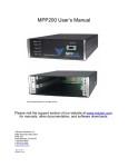
The Media Processing Platform (MPP) 1700 is a high density, rack mount blade chassis used in
VSI IPTV applications.
Slots 1-17 on the chassis can be filled with any VSI blade product. Slots 18 and 20 can be filled
with power supplies. At least one of the power supply slots must be filled, and for dual redundant
power supply support, both power supply slots must be populated.
1.2.1 MPP1700 Front Panel Slots
Power Supply
Slots
Blade Slots
1.3 Rack Mounting the MPP1700
Warning: Before installing the MPP1700, be sure to read the safety and equipment
information contained in this chapter.
Caution: Use proper electrostatic discharge (ESD) precautions when installing or removing
the MPP1700 to avoid damaging the unit’s circuitry.
The MPP1700 is designed to be mounted in a standard 19-inch rack and to be oriented such that
the card insertion, cabling and indicators are facing out the front of the rack. Only the AC power
connection is located on the back of the unit. It will utilize 3U of rack space, but space should be
left above and below the unit for proper cooling. See the sections that follow for cooling
requirements and information on installing blanking panels.
2
MPP1700 User’s Manual
In order to install the MP1700 on a 19-inch rack, you will need four screws and a screwdriver.
1. Locate the four holes, two per bracket, on the left and right mounting brackets attached to the
front of the chassis.
2. Lift the empty chassis and place it inside the rack. The mounting brackets of the MPP1700
must remain on the outside of the rack.
3. Attach with screws and tighten to secure the unit.
4. Connect the power cable to the rear of the unit. A power switch is provided near the AC
power connection so that it can be turned on when the unit is properly installed and ready for
operation.
1.4 Hardware Inventory
Your MPP1700 will be shipped with one US IEC Power Cable and one RS-232 cable.
1.5 Blade Installation and Removal
Note:
It is important that the module be properly aligned with the slot guides before it is inserted
into the appropriate slot on the chassis. It is recommended that the user’s line of sight be
level with the middle of the backplane in order to see both slot guides clearly.
Install a VSI blade into the chassis as follows:
Caution: Use proper ESD precautions when installing or removing a VSI blade to avoid
damaging the unit’s circuitry.
1. Slide the blade, open end first, into the desired slot on the chassis until it plugs into the
connector located on the backplane at the rear of the unit.
2. Use the bottom ejector handle to securely seat the blade into the chassis and to properly
mate the rear connectors. The handle should lock closed when properly inserted to secure
the unit.
3. Tighten the captive thumb screw located at the top of the blade to provide a more secure
mounting.
4. If desired, an additional Phillips screw can be installed through the handle.
5. The Status LED will blink once per second when the blade is properly installed, powered, and
operational.
3
MPP1700 User’s Manual
To remove a VSI blade:
1. Loosen the mounting screw at the top of the blade.
2. If installed, loosen the additional Phillips screw in the ejector handle.
3. Press the red tab on the bottom of the ejector handle to unlock the blade.
4. Pull down on the handle and pull the blade out of its slot away from the chassis.
1.6 Power Supply Installation
Warning: Before installing the power supply, be sure to read the safety and
equipment information contained in this chapter.
Caution: Use proper ESD precautions when installing or removing the power supply to
avoid damaging the unit’s circuitry.
Note:
Slots 18 and 20 can only be populated with a power supply module.
Note:
It is important that the module be properly aligned with the slot guides before it is inserted
into the appropriate slot on the chassis. It is recommended that the user’s line of sight be
level with the middle of the backplane in order to see both slot guides clearly.
To install a power supply:
1. Slide the module, open end first, into slot 18 or 20 on the chassis until it plugs into the power
connector located on the backplane at the rear of the unit.
2. Use the bottom ejector handle to securely seat the module into the chassis and to properly
mate the rear connectors. The handle should lock closed when properly inserted to secure
the unit.
3. Tighten the captive thumb screw located at the top of the module to provide a more secure
mounting.
4. If desired, an additional Phillips screw can be installed through the injector handle.
5. The Input OK LED will illuminate green when the supply is properly installed, power is
applied, and the system is operational.
6. The Fault LED will illuminate red if a fault condition is detected.
4
MPP1700 User’s Manual
To remove a power supply:
1. If tightened, loosen the captive thumb screw at the top of the front module.
2. If installed, loosen the additional Phillips screw in the ejector handle.
3. Press the red tab in the bottom injector/ejector handle to unlock the module.
4. Pull down on the handle and pull the module out of its slot away from the chassis.
1.7 Installing Blanking Panels
After all blade options have been installed, all empty slots must be populated with blanking
panels. Install blanking panels as follows:
Warning: Failure to populate empty slots with blanking panels will impede cooling
and may cause the MPP1700 to overheat. Failure to populate empty slots
with blanking panels will also negatively effect EMC radiation and immunity.
Note:
Blanking panels are available to cover each of the unused blade slots. A different panel is
used to cover an unused power supply slot than for the blade slots. Two standard blanking
panels can be used to cover a power supply slot if desired.
1. Place the blanking panel onto the face of the MPP1700.
2. Tighten the two captive screws on the front of the blanking panel.
1.8 Cooling
The MPP1700 has top and bottom vents in its cover to allow for proper cooling. These vents
must be left unobstructed. Airflow is directed out of the rear of the unit. These fan ports must also
be left unobstructed. Inproper restriction of air flow could result in unit failure or reduced
operational life. Thermal management of the equipment rack must be properly handled to avoid
possible problems.
1.9 MPP1700 Safety and Compliance
Rating Information:
Caution: 100-240V~, 50-60 Hz, 3A
Fuse Rating:
Caution: 250V, 3.15A, SlowBlow
5
MPP1700 User’s Manual
Fuse Replacement Caution:
Caution: For continued protection against fire, replace fuse with same type and rating.
Caution: Double pole/neutral fusing.
Safety Approvals:
UL Listed I.T.E. E257717
6