1
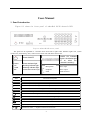
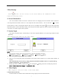
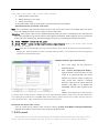
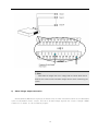
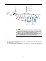
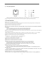
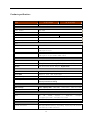
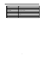
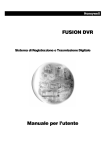
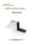
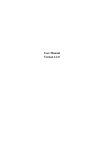
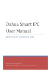
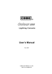
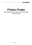
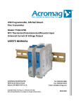
Embedded 24/32 channels Digital Video Recorder Function and technology characters Monitor Function: With 2 channels BNC output and 1 channel VGA display. Particular one channel with OSD menu display output and another real time monitor output. System offers modification for both channel position and image size. Shelter zones can be set by the user for raising the security level. Matrix Function: Embedded with 32*4 matrix output, each channel can be set to view the 32 channels alternately according to the time set. Record Function: Video compression with MPEG-4/H.264 changeless/changeable bit stream and changeable frame rate. Multiple recording modes: manual recording, schedule recording, alarm recording, motion detection recording, and pre-recording. Replay Function:Multiple channels available for replaying while the 24/32 channels are all recording the video & audio in real time. Achieve the development from only can replay in one channel. Designed for time schedule structure, system provides fast and accurate searches. Storage Function: Embedded SATA hard disks used, power for disks separately supplied according to the command, non working disks asleep in order to prolong the working term of the disks; UST2.0 high speed backup connection port; record data can be backup by multiple ways such as USB remote disks and network. Indicator Lights:Independent disk indicator lights reflect the working statuses of 6 disks directly, easier for user to check out the problem. Temperature Control Function: Fan and temperature control offered, speed of the fan changeable, heat extension controlled efficiently. Voice Communication:Voice communication function, LINE IN and LINE OUT ports on the front panel, bidirectional voice communication available. Alarm Function: Each channel has 192 independent motion detection areas, detection sensitivity (0~99) adjustable, 12 channels input from outside alarms, 3 channels alarms output for alarming linkage; functions as recording, switching on/off, voice and light, electronic map switch, P/T/Z pre-set position, send alarm massages and relative videos to authorized computers associated are available. Multiple alarms for password failure, video lost and video shelter are supported. Control Function: Compatible with multiple communication protocols to control the P/T/Z camera, ball, and matrix; Compatible with multiple alarm port communication protocols to start or stop the alarming devices; remote keyboard, particular keyboard are used to control the DVR. Network Function: Multiple channels monitoring, recording, data downloading, replaying, data searching and controlling in real time from distant network; parameters setup, modification and software update from distant network; P/T/Z camera control, alarming device control from a distant network; embedded with WEB SERVER, controlled 1 through the IE browser directly; supports stream protocols (RTP/RTCP,RTSP), network group display; adjusts the network stream bit automatically, adopts for all the network environment; supports network time synchronization; supports centralized management of the network alarming center. Management Safety: Three-level user rights, multiple passwords control to prevent data from being modified and deleted. Protect Function: Over current, voltage and short circuit protection circuit in the power supply incoming port. 2 LIST 1. PANEL INTRODUCTION....................................................................................................................... 4 2. REMOTE CONTROL.............................................................................................................................. 5 3.HOST STARTUP........................................................................................................................................ 7 4. SCREEN INFORMATION ...................................................................................................................... 7 5. SYSTEM LOGIN ...................................................................................................................................... 7 6. VIDEO REPLAY....................................................................................................................................... 7 7. P/T/Z CONTROL...................................................................................................................................... 8 8. CAMERA CONTROL .............................................................................................................................. 9 9. ALARM ELIMINATION ....................................................................................................................... 10 10. MANUALLY START/STOP RECORDING ....................................................................................... 10 1) Start recording..................................................................................................................................... 10 2) Stop recording...................................................................................................................................... 10 11. MANUAL TIME CHECKING............................................................................................................. 11 12. DATA BACKUP .................................................................................................................................... 11 13. SIMPLE SETUP.................................................................................................................................... 11 1) Format The Disk: ................................................................................................................................ 11 2) System Parameters Setup:.................................................................................................................. 12 3) Record Parameters Setup:.................................................................................................................. 12 Schedule recording setup:........................................................................................................... 13 Alarm recording setup ................................................................................................................ 13 Motion detection recording ........................................................................................................ 14 14. SIMPLE INSTALLATION GUIDE..................................................................................................... 15 1) Back panel of 32 channels DVR ......................................................................................................... 15 2) Audio input connection:...................................................................................................................... 16 3) Video output connection: .................................................................................................................... 16 4) Matching resistance: ........................................................................................................................... 16 5) Sensor input connection:..................................................................................................................... 16 6) Alarm linkage output connection....................................................................................................... 18 7) P/T/Z control connection .................................................................................................................... 19 8) RJ11 ports explanation ....................................................................................................................... 20 15.NORMAL QUESTIONS........................................................................................................................ 20 PRODUCT SPECIFICATION: ................................................................................................................. 22 3 Users Manual 1. Panel Introduction Figure 2-1 shows the front panel of embedded 24/32 channels DVR. Fig.2-1 24/32 CH DVR front panel The panel can be separated to 5 function areas from left to right: status indicator lights area, system control area, numeral keys area, video record control area and menu control area. 1-24/32 CH indicator lights(the relative light is on when the channel is working) Power ON/OFF ALARM Power indicator light Running indicator light Alarming indicator light HDD 6 SATA disks indicator light POWER RUN Microphone Earphone USB Title Voice input Voice output USB connector Function Description 0 ①Numeral Key “0”; 1 ①Numeral Key “1”;②Display channel 1 in single either full screen mode; 2 ①Numeral Key “2”;②Display channel 2 in single either full screen mode; 3~9 ①Numeral Key “3”~“9”;②Display channel 3 ~9 in single either full screen mode; Plus 10,used for single screen switch, followed by the numeral key Automatic scan, scan a single screen or multiple screens within a certain time Cancel alarm, either cancel the alarm voice or linkage output Multiple screens switch, 32, 25, 16, 13, 9, 6, 4 and single screen switch PTZ Choose and cancel PTZ control mode Preset ①Quick way to “PRESET INFORMATION”; ②Preset point under PTZ control mode Z/ ①Electronic zoom; ②-brightness under PTZ control mode 4 F/ ①Image freezing; ②+brightness under PTZ control mode F1/ ①Obligate;②Camera closer focus under PTZ control mode Backup/ ①Quick way to “VIDEO BACKUP”; ②Camera further focus under PTZ control mode F2/ ①Obligate; ②Zoom out the camera under PTZ control mode; Search/ ①Quick way to “VIDEO SEARCH”; ②Zoom in the camera under PTZ control mode; ①Start the current channel manual recording; ②Save the P/T/Z’s original position of the current channel; ③Disk directory inspect ■ ①Stop record of the current channel;②Stop replay; ③Call current channel’s P/T/Z back to the original position ①Start replay of the current channel; ②Back to normal speed play from fast forward, fast backward and slowly play mode; ③Play the video frame by frame under the pause mode;④Play the video by 1/2 of the normal speed; Pause the current replay Play forward the video as 2, 4, 8 times as the normal speed Play backward the video as 2, 4, 8 times as the normal speed Play the next video section Play the previous video section CONFIRM ESC Menu ①Same as “YES” under the menu or window status; ②Confirm/cancel motion detection area;③Set a shield area ①Same as “Cancel” under the menu or window status; ②Back to menu/window status from motion detection area set status; ③Quit motion diction area set status; ④Set/Cancel the silence mode; Enter system menu mode ① “UP” direction; ②Control P/T/Z moves upward under PTZ control mode; ③Set motion detection area moves upward; ④Set zoom in area moves upward ① “DOWN” direction;②Control P/T/Z moves downward under PTZ control mode; ③Set motion detection area moves downward; ④Set zoom in area moves downward ① “LEFT” direction;②Control P/T/Z moves leftward under PTZ control mode; ③Set motion detection area moves leftward; ④Playing backward as 2, 4, 8 times as the normal speed ① “RIGHT” direction;②Control P/T/Z moves rightward under PTZ control mode; ③Set motion detection area moves rightward; ④Playing forward as 2, 4, 8 times as the normal speed 2. Remote control Figure 2-2 shows the remote control of embedded 24/32 channels DVR 5 the remote control’s basic keys are almost similar with the front panel,except the following special keys. Special keys Function Description Select Input the Remote control’s address (000~999) P/Z Choose and cancel PTZ control mode SETUP ①10+;②Save the PTZ’s original position of the current channel under the PTZ control mode; SAVE Preset point under PTZ control mode RETURN Call current channel’s P/T/Z back to the original position ①Playing forward as 2, 4, 8 times as the normal speed;②Camera further focus under PTZ control mode ①Playing backward as 2, 4, 8 times as the normal speed;②Camera closer focus under PTZ control mode ①Play the next video section;② + brightness under PTZ control mode ①Play the previous video section;② - brightness under PTZ control mode ■ ①Stop record of the current channel;②Stop replay;③Zoom out the camera under PTZ control mode; ①Pause the current replay;②Zoom in the camera under PTZ control mode Multiple screens switch CANCEL ①Same as “Cancel” under the menu or window status; ②Back to menu/window status from motion detection area set status; ③Quit motion diction area set status; ④Set/Cancel the silence mode; 6 3.Host Startup Click button , the host startup. On the screen displays the information of disk inspection processing status. 4. Screen Information “UP” and “DOWN” buttons are used to control the cursor for changing the current channel. There would be a voice output from the monitor if there is a voice input from the current channel, user can click the “ ”(remote control) button or “ESC” (control panel) button if the voice is not needed. The symbol “ ” in front of the system date means the system is now in the silence mode, if click the previous button again, the system is back to the mode with voice, there is no need to login for this operation. 5. System Login User clicks any button expect “Numeral Keys” and “Screen Separate Buttons”, the system login window will be popped up. The following figure shows the user login window: Note: The maximum number of the system password is 6, here are the default passwords: ※ Manager——333333 ※ Operator——222222 ※ Browser——111111 Three times password input failure causes an alarm. If the user is not using the system, the keyboard of the system will be locked on for a certain while. Default: 10 minutes. Note: The lock time can be reset by setting “Keyboard automatic lockdown time” in “System menu→ Facility management→System parameters”. Modify password: user enter “System menu→User management→Modify password” to modify the password. Note: Please keep the manager’s password safe. 6. Video Replay While logged in, there are totally 3 video replay modes: 1).Main menu/Search files: Channel Number: the number of the channel that is being replayed; 0 means all the channels 7 Just search the events video: events video include: External alarm event videos Motion detection event videos Timing event videos Credit card number: input the card number, search records by the card number This function needs a particular card reader. Note: User is allowed to get maximum 5000 records for each search, the records exceed 5000 will not be listed. User may change the search criteria to get the expected video data. Indication: If the current video record is finished replaying while the system is searching for the video data, the next video record fits for the search criteria will be replayed continually. While replaying, user can operate the video such as fast forward play, fast backward play and pause by controlling the buttons on the panel. 2). Click “SEARCH” button on the panel 3). Click “PLAY” button in the record control area directly: Replay the latest video record of the current channel Note: While there are less than5000 records in the disk and click the “PLAY” button, the latest record of the current channel is being played. While the number of records is more than 5000 in the disk, it is not the latest record which is being played, but the latest in the listed 5000 records. Multiple channels replay simultaneously 1. First of all, replay the first channel as mentioned before; 2. Enter “System menu→Search Replay”, input the search criteria and choose a video record to be played through the second channel. For instance, if want to replay the video record from channel 5 through channel 2, input 05 in the search criteria of channel 2, the others is 0 as default, and CONFIRM. Operate other channels as the same. Note: The first channel can be replayed directly by clicking “PLAY” button, the other 3 channels can only be replayed through input the search criteria. Full screen mode and 4 screens mode can be switched by the “CONFIRM” button. While replaying, only the replayed video is visible, if the user wants to go back to the monitor mode, “STOP” button must be clicked to quit the replay mode. Demand for the earliest video record User can search for the earliest video record by entering “System menu→Data management→Earliest record”. This makes it easier to know how many days the DVR works. 7. P/T/Z control System offers the function of controlling the P/T/Z move horizontally or vertically. P/T/Z preset position and original position can be set while the P/T/Z is being controlling. 8 Note: The P/T/Z decoder parameters have to be set before the P/T/Z can be controlled. Operation steps: 1). User clicks “PTZ” (panel) button or “P/Z” (remote control) button on the channel which is connected to P/T/Z. 2). A symbol“ 3). User uses “ ”is displayed in the lower middle of the screen. ” and “ ” button to move the P/T/Z vertically. 4). User uses “ ” and “ ” button to move the P/T/Z horizontally. 5). If the user needs to save the current position of the P/T/Z, click “Preset” (panel) or “SAVE” (remote control) to save it as a pre-set position. 6).If the user needs to set the current position of the P/T/Z as an original position, click “ ” (panel) button or “SET” (remote control) button. 7). If the user needs to go back to the original position from the current position of the P/T/Z immediately, click “■”(panel) or “BACK/CANCEL”(remote control), system will call P/T/Z back to the original position. 8).If the user clicks “PTZ” (panel) or “P/Z” (remote control) button under the PTZ control mode, the system will quit the PTZ control and back the normal monitor mode.. 8. Camera Control This offers the zoom in/out function for the camera. User can set either pre-set position or original position of the P/T/Z while controlling the camera. Operation Steps: 1). Click “PTZ” (panel) or “P/Z” (remote control) under the P/T/Z control mode. 2). When the system enters the camera focus control mode, there will be a symbol “ ” displayed on the middle down of the screen. 3). Use “ ”/“ ” button to zoom in/out the camera’s focus. 4). Use “ ”/“ ” button to zoom in/out the image. 5).Use “ ”/“ ” button to change the color light/dark. 6).If the user needs to save the current position of the P/T/Z, click “ ”(panel) or “SAVE”(remote control) button and the system will save the current pre-set position for the P/T/Z. 7).If the user needs to set the current position as the P/T/Z’s original position, click “●” (panel) or “SET” (remote control) button, system will save the current position as an original position. 8). If the user needs to go back to the original position from the current position immediately, click “■” (panel) or “BACK”(remote control) button and system will call the P/T/Z back to the original position. 9). If the user clicks “PTZ” (panel) or “P/Z” (remote control) button under the light control mode, the system will quit the light control and back the normal monitor mode. 9 9. Alarm Elimination The function of alarm elimination offers the user to make acknowledgements of output alarms from the system. If the user clicks “ ” button when the alarm is on, the system will stop all the alarm output including the inside buzzer. Note: This function is only for eliminating the current alarms but not the future alarms, meanwhile other functions of the system such as recording will not be effected. 10. Manually START/STOP Recording 1) Start recording The system offers the user to start recording in a chosen channel. Different from auto recording, manual recording mode lasts forever until the user stops it. Operation steps: 1). Click “●” button on the current channel 2). System starts record on the current channel and a symbol “●” is displayed on the middle down of the screen. The quality of record can be set through “System Menu→Equipment Management→System Parameters Set”. 2) Stop recording User can control the system stop recording by this function while the system is recording. The recording modes such as manual recording, schedule recording, alarm recording and motion detection recording can all be stopped. Operation steps: While under the manual recording mode, if the user holds on click “■” button for 2 seconds, the current channel recording will be stopped, hold on for 5 seconds then all the channels will be stopped. When it is under schedule recording, alarm recording or motion detection alarm recording mode and the trigger source exists( for detailed trigger source, please reed “schedule recording”, “alarm recording”, “motion detection recording” sections), if the user holds on click “■” button for 2 seconds, the current channel recording will be stopped, hold on for 5 seconds then all the channels will be stopped, but when the trigger source exists again, the relative channels will start recording again. System calls the P/T/Z back to the original position if it has been changed during recording. 10 11. Manual Time Checking Operation steps: 1). Enter “System menu→Equipment Management→System Time” 2). A dialogue window displays the system time which can be modified by the numeral keys. 3). Click the “CONFIRM”/“CANCEL” button to save/ cancel the modification. 12. Data Backup This function saves the video data from the host to other storages through USB port. Operation steps: 1). Enter “Backup”Or“System Menu→Data Management→Data Backup” 2). Click “CONFIRM” button and a search window “Video data backup condition” popped up which is similar to the replay search function. 3). Click “CONFIRM” after finish inputting the search criteria of the expected data. 4). Click “CONFIRM” after finish choosing the expected data file. Note: Be sure that there are non MP4 format files in the USB storage, they might be deleted. 13. Simple Setup 1) Format The Disk: Enter “Equipment Management→Disk Management”, click “CONFIRM” to format the disk. 11 2) System Parameters Setup: 1). Power on auto-recording: NO; if it has being set “YES”, system is in manual recording mode no matter how the recording schedule is set. 2). Record overwrite: AUTO, which means the earliest record will be overwrote automatically when the space is full, meanwhile an information dialogue will be popped out. 3). Alarm buzzer: NO, the buzzer alarm occurs when there is an alarm input (external alarm, motion detection alarm) if it has been set “YES”. 4). Alarm screen switch: NO, the screen is switched to the alarmed channel when there is an alarm input from the channel(external alarm, motion detection alarm) and will be back after the alarm is finished. 3) Record Parameters Setup: 12 Schedule recording setup: Operation steps: 1).Choose “SCHEDULE RECORDING” through the menu. 2). Click “CONFIRM” to enter the schedule recording parameters setup menu, use “UP” and “DOWN” to control the cursor, “LEFT” and “RIGHT” to input or choose the parameters. 3). Channel number: video channel number of the DVR 4). Video record quality: bad, normal, good, better, best; default: good 5). Video frame rate: FULL、1/2F、1/4F、1/8F、1/16F;default:FULL 6). Video stream bit: CBR(changeless)or VBR(variable); default: CBR 7). Video time: Sun., Mon., Tue., Wed., Thurs., Fri., Sat. and FULL. Two periods of time can be set for each day, “FULL” means each day with the same time set. Default: schedule recording off; Set “OFF” to “ON” after finish setting each period of time. 8). If all the channels’ parameters wished to be the same when setting the schedule recording parameters, choose “ALL” button after set one channel’s parameters, system pops up a dialogue, when click “CONFIRM” then all the channels’ parameters have been set. Alarm recording setup Input port: external alarm input port; 24/32 channels DVR: 01-12 Output port: relay output port; 24/32 channels DVR: 3 Alarming time: linkage relays output time Recording time: linkage channels’ recording time 13 P/T/Z movement: linkage P/T/Z moves back to the pre-set position Recording channels: linkage recording channels, multiple channels available Alarm input type: the type of external alarm trigger, NO (normal open) or NC (normal closed) Motion detection recording Embedded DVR starts the motion detection recording if the image that has been detected by the camera is changed. In motion detection recording mode, user is allowed to set each channel’s motion detection sensitivity, motion detection area, P/T/Z movement, record time, video quality, alarm output port, alarm output time and also periods of time for alarm recording. Operation steps: 1). Choose “Motion detection recording” through the menu. 2). Click “confirm”, enter the motion detection recording menu, use “UP” and “DOWN” to control the cursor, “LEFT” and “RIGHT” to choose or set the particular value of the parameters as shown in the following figure: Motion detection alarm recording is basically based on the alarm recording which is particular for motion detection alarm. In this section, two parameters (detection sensitivity, detection area) will be introduced in detail. 3). Detection Sensitivity: The sensitivity of motion detection alarm when the system is detecting the images. The arrange of sensitivity is 00-99 with the lowest sensitivity 00. Default value:50; Consult value: 40-70. 4). Click “SETUP” and a dialogue of motion detection area setup will be popped up as shown in the following figure. 14 “Motion detection area” can only be set in the green area; the big green area except the white part is so-called “motion detection area” In this dialogue, user is allowed to click “UP”, “DOWN”, “LEFT” and “DOWN” to control the cursor, click “CONFIRM” to set or clear the area, click “CANCEL” to go back to the parameters setup window. 14. Simple installation guide 1) Back panel of 24/32 channels DVR The following figure shows the back panel appearance of 24/32 channels DVR. The height of the case is 2U,and the dimension of its body is 440×100×520(mm). The following figure shows the ports of audio input/output, video input/output and P/T/Z control input/output of 24/32 channels DVR. 15 2) Audio input connection: On the back panel of the DVR, there are BNC audio/video input connectors which can be connected to camera and audio input device directly. 3) Video output connection: DVR host has 2 channels CVBS simulated video output and 1 channel VGA output; both of BNC and VGA connectors can be connected to DVR or monitor directly; The assistant video output does not have OSD menu output but the main video output has. 4) Matching resistance: The matching resistance is between VGA and RS422; two switches are responsible for matching 120 ohm for sending and receiving. Turn down the switch means to avoid the resistance while turn on the switch means to parallel connect the resistance. The matching resisitance only has influence upon RS422 5) Sensor input connection: The voltage signal of the external sensor can be connected to the alarm input port of. By default, a “LOW” value voltage signal of the external senor causes an alarm input to the DVR, contrarily, a “HIGH” value voltage signal of the external senor causes no alarm input to the DVR. While the output of the sensor is connecting with the DVR as an input, the signal should be connected to “ALARM IN” port and earthing port to GND. For 24/32 channels DVR, the 16 up DB25 is used for audio input and the down DB25 is used for sensor signal. The definition of the ports is showed in the following figure. Table 8 Ports definition of up DB25 Table 9 Ports definition of down DB25 PIN# Port definition PIN# Port definition PIN# Port definition PIN# Port definition 1 AUDIO IN1 14 GND 1 ALARM IN1 14 GND 2 AUDIO IN3 15 AUDIO IN2 2 ALARM IN2 15 NO1 3 GND 16 AUDIO IN4 3 ALARM IN3 16 NC1 4 AUDIO IN5 17 GND 4 ALARM IN4 17 COM1 5 AUDIO IN7 18 AUDIO IN6 5 ALARM IN5 18 NO2 6 GND 19 AUDIO IN8 6 ALARM IN6 19 NC2 7 AUDIO IN9 20 GND 7 ALARM IN7 20 COM2 8 AUDIO IN11 21 AUDIO IN10 8 ALARM IN8 21 NO3 9 GND 22 AUDIO IN12 9 ALARM IN9 22 NC3 10 AUDIO IN13 23 GND 10 ALARM IN10 23 COM3 11 AUDIO IN15 24 AUDIO IN14 11 ALARM IN11 24 GND 12 GND 25 AUDIO IN16 12 ALARM IN12 25 GND 13 +12V 13 The following figure shows how to connect the ports: 17 Note DVR offers an output with +12V voltage and 3A current which can be used for most of the sensors and alarm output devices when constructing the system. 6) Alarm linkage output connection 24/32 channels DVR offers 3 groups of alarm control connectors which can be set as NO(normal open) or NC(normal close) status. All the 3 alarm linkage signals are output through a DB25 connector as shown in the following figure: 18 Note: When there is no output signal from the system, “NO” port and “COM” port keeps open, but “NC” port and “COM” port keeps closed; When there is an output signal from the system, “NO” port and “COM” port keeps closed, but “NC” port and “COM” port keeps open; 7) P/T/Z control connection DVR controls multiple P/T/Z movements through RJ11 and 422 bus thread and distinguish P/T/Z by the addresses set by a decoder. 001-256 P/T/Z addresses have being defined by a 24/32 channels DVR; any 24/32 of them can be selected for using. The following figure shows the connection sketch map. 19 8) RJ11 ports explanation Follow the sketch map and make the connecting lines. For the RJ11 ports, 1, and 2 are alternatively the positive and negative port of the sender while 3 and 4 are the positive, negative ports of the receiver; 15.Normal questions Q1:Why there is no image on the monitor? A1: First of all, check if the host case and monitor have been connected correctly and powered on. Presently, DVR has its own power switch, make sure it has been open. Q2:Why the real time monitor image is not clear? A2: Check if the connectors have been connected rightly, if they have been lax, then should be replaced or re-soldered. Check if the aperture and focus of the camera have been adjusted well. Also, can reset the lightness and contrast from the DVR system menu. Q3:Why the motion detection alarm does not work correctly, means while there is a person moving in the image but does not trigger the alarm? A3:The accuracy of the motion detection alarm is related to the image from the camera, try to set another sensitivity of the detection to test the camera and find the best sensitivity. The value is 40-70 by consult. Q4:Why the video records can not be overwrote automatically? A4: Reason one: “Auto overwrite record” has not been set on Reason two: Disk mistakes, need to format the disk. Q5:How many recording modes are available? A5:Schedule/motion detection/alarm/manual recording Q6:Why there is no audio information for one channel? A6:Check if the ports and the connecting lines work fine, if not, try to use another line. If the ports and the connecting lines are fine, check if the monitor works normally. Check if the silence button on the remote control has been clicked, if has, do it again. Q7:Why the remote control does not work? A7:Check if the battery is built in correctly and with enough electricity. Check if the remote control has been used correctly, if there is a symbol “F” on the left down corner of the video, click “F”. See if the control address of the remote control is the same as the address in the DVR, if not, then change the address to 000 or the address in DVR. Q8:What should I do if I hear the buzzer when starting the system? A8:This product is set to trigger the alarm when starting the system if there is a wrong operation or 20 parameter setting, so this buzzer is mainly because of no video input. Login as the manager and cancel the buzzer; Check if there is a read/write mistake of the disk, stop recording and format the disk if it has such a problem. Q9:Why can not control the movements of P/T/Z? A9:Check if the P/T/Z control parameters in DVR menu such as protocol, baud rate and the address have been set correctly. Check if the RS connecting lines(Tx+、Tx-) of the decoder are correct, and measure if there is a voltage change between the Tx+、Tx- lines(if the connection is correct and no voltage change between the lines, it might be the problem of the 485 control chip). Be sure that there are no above mistakes, then check the protocol, compare it with the protocol’s format from the decoder factory through the serial port. Q10:How to use USB to backup the data? A10:Firstly, connect the hard disk with the USB port, enter “System Menu→Data Management→ Data Backup”, select the expected data files. Note: If there are non MP4 format files in the disk, then they might be deleted while try to backup the data files, and the backup files in the remote disk can only be read by a particular software, otherwise the disk will not be recognized by the computer. 21 Product specification: MODEL Main processor 24 CH DVR(M) 32 CH DVR(M) High quality embedded MPU processor VIDEO Video Format PAL/NTSC Image Compression Standard MPEG4/H.264 Video Input 24 CH BNC (1.0Vp-p,75Ω) Video Output 2 CH BNC (1.0Vp-p,75Ω),1 CH VGA Matrix Output 4 CH BNC(1.0Vp-p,75Ω) 32 CH BNC (1.0Vp-p,75Ω) AUDIO Audio Compression Standard G.723/ADPCM Audio Input DB25,16 CH input(100mv-500mv,10KΩ) 1 MiniJack input Audio Output 1 CH BNC(100mv-500mv,600Ω) 1 MiniJack output(100mv-500mv,1KΩ) DISPLAY Resolution D1:704×576(PAL) 704×480 (NTSC) Video Standard PAL (625 threads,50f/s),NTSC (525 threads,60f/s) Division 1/4/6/9/13/16/25/36 images,Digital Zoom RECORDING Resolution CIF(352*288)PAL,CIF(352*240)NTSC Frame Rate 25FPS in real time,adjustable Image Quality Recording Mode 5 Levels (Low,Normal,Good,Fine,Super) Manual/Schedule/Event(Motion detection/Alarm Sensor)/Auto/Pre-recording HDD Basic storage 6HDD capacity Max.:500G/HDD,independent indicator LED Requirement 1CH audio:14.4M/Hour;1CH video: 35-1000M/Hour Alarm Input 12 CH alarm inputs , High/Low trigger(optional),extended I/O input Output 3 CH alarm outputs, 1A 24VDC/120VAC voltage OTHER System resources Multiple CH monitoring, recording, replaying and network controlling simultaneously 22 Network RJ45 USB devices 2 PTZ camera RS485/422,RJ11 Power supply AC100~240V 50/60Hz Power(no HDD devices) <70W Color Black Height 12.5 KG Dimensions (W×H×D) 440×100×520 mm 2U Operating environment 10~95% OH, -10℃~55℃ USB2.0 23