1
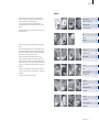
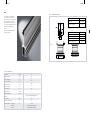
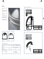
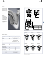
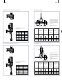
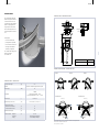
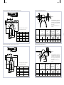
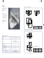
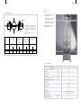
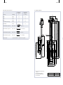
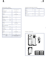
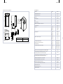
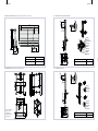
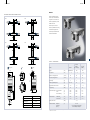
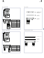
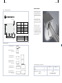
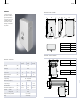
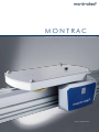
Montrac Increasing productivity thanks to flexible and intelligent intralogistics 10/2011 English edition MONTRATEC-REFERENCES 4 montrac Montrac in Use by ... «With montratec’s technology, we could customize the transport system according to our production needs, eliminating dust, reducing consumption and optimizing the entire production cycle.» Vincenzo Lioy, Managing Director, Triom Antistatic and low power consumption «With Montrac we have saved time, optimized production processes and the efficiency of labor, and freed up space.» Maurizio Romagnoli, owner of Tech-Pol s.r.l. Efficient and fully automated intralogistics «Based on a positive result gained in a project, we know we can find a suitable solution to satisfy the requirements in terms of compact dimensions, small footprint, compatibility with aseptic environments, reliability and high availability.» Thomas Otto, CEO of Vetter Pharma-Fertigung GmbH & Co. KG Unattended intralogistics in the clean room «We are very satisfied with the result and service of montratec. Currently we are planning the implementation of two more Montrac lines.» Ulrich Wilke, Production Manager of SEIKO Optical Europe Laboratory Flexibility for the future montrac 7 Contents Montratec manufactures modular components used to automate demanding production and logistic processes. In addition to conventional belt c onveyors, automation components, and the Quick-Set profile system, our range of products features the Montrac transport system. Montrac is an intelligent transport system for networking industrial production and logistic processes. Montratec, headquartered in Switzerland, has been pioneering advances in industrial automation since 1963. Solution Paths 8 Montrac-Configurator 12 Control System 14 Chaos Technology 16 Trac18 TracLink20 Traccurve22 Montrac is an intelligent conveyor system for industrial production and logistical processes. Montrac exemplifies total flexibility when it comes to conveyor technology, providing virtually limitless possibilities combined with user-friendly s implicity throughout the entire system. Montrac has been optimizing production processes and intralogistics in innovative companies worldwide for over a decade. The Montrac intra-logistic solution guarantees that products are arriving at the proper destination at the right time. More importantly, it takes the most efficient path. When one wants to increase productivity, the first thought is often to increase machinery. However, this is not always necessary! The quickest and most cost-effective way to increase your p roductivity is to streamline and automate your material flow. Tracswitch28 TracSWITCH ARENA 32 TracCrossing36 LIFT39 Shuttle51 While this is not always feasible with conventional conveyors, the Montrac transport system can help you implement your productivity objectives – simply, flexibly and profitably. Pallet55 «Let us be a part of your success, get on the right Trac!» Positioning Unit SupoTrac /Ergotrac57 60 TRACDOOR68 Frameworks70 Intelligent modules 82 TouchPanel84 LOGIBOX86 Power Supply 88 Special Components 91 Accessories97 Modification reserved 8 montrac montrac 9 SOLUTIONS FOR YOUR PRODUCTION SYSTEM RELIABILITY Are you planning a new production system or expanding an existing production facility? The Montrac monorail system provides you with fast and flexible solutions. Montrac is an intelligent transport system networking industrial production and logistic processes. Montrac is the most reliable system available for transporting your p roducts. Traditional conveyors’ heavy-wear items like belts and chains are single points of failure. Since a Shuttle can be easily removed from the production process without stopping the system, there is no production downtime when Montrac is transporting your goods. The Trac itself is a passive element and not subject to failure. The Shuttles and switches are the only active components in your system, and they were designed to be virtually maintenance-free. Envision your production and logistics in the future – Montrac can help you realize that vision today. Montrac will revolutionize your logistic and production workflow. SIMPLICITY Montrac was designed to be extraordinarily simple. It is comprised of very few components, making design and assembly very easy compared to ordinary conveyor systems. The Trac components are quick to assemble. Other than a straight cut, there are no machining processes required. The exclusive use of electronic components eliminates the need for pneumatic connections and complicated wiring. Chaos Technology greatly reduces cabling and programming. You will benefit from this simplicity not only during assembly but also when changing or expanding your conveying system. APPLICATION EXAMPLES Intra-logistics and assembly line In one of the largest engine plants in the world, production and logistics must be perfectly synchronized. Space is a premium and every square meter has to be optimized. The pistons are manufactured several hundred meters from final assembly. Montrac serves as both the transport system in the assembly line and as a fully automated delivery system to the final assembly area. For this application, Montrac was, by far, the least expensive and most effective solution. FLEXIBILITY Your needs are our primary focus. We designed Montrac to be flexible enough to implement tomorrow’s conveyance needs today! All Montrac components have the same basic design and are compatible with each other. So what you install now to meet today’s needs can be reused tomorrow to meet future needs. The bypasses, switches and curves are compact to fit in tight spaces and maneuver around obstacles. Montrac is flexible in ways that conventional conveyors could never be. Connecting injection molding machines and other machines One of the most successful manufacturers of headlights uses Montrac for connecting its injection molding machines to the protective coating process. Thanks to the completely antistatic properties, cleanliness u nparalleled flexibility of Montrac, the system paid for itself in less than 18 months. Testing while traveling A prominent manufacturer of tachometers uses Montrac in assembly. Each cluster has to go through a test station in the assembly line. Montrac makes it possible to start up the software and perform the testing during travel thanks to the additional 24 VDC electrical power supply on the Shuttle. The manufacturer was able to cut costs by eliminating several cost-intensive test stations. cleanroom Montrac is perfectly suited for cleanrooms. The shuttles are self-propelled and therefore have no dirty belts. There is no sliding friction to create particulate. Even its form reduces air turbulence. The standard components were designed for a class 1000 cleanroom. With minor adjustments we have reached class 100 according to US Federal standard 209E. 10 montrac montrac 11 PROFITABILITY & COST EFFICIENCY MONTRAC – FOR A CLEANER ENVIRONMENT Montrac’s latest developments are aimed at increasing the system’s efficiency. Montrac is not only attractively priced, it is also environmentally friendly. A conveyor belt system with 34 motors consumes $20,000 worth of electricity a year, whereas a comparable Montrac system only consumes $600. This equates to a significant reduction in environmental impact. Montrac is driven solely by electricity – there are no costly pneumatic components or connectors. Power is supplied directly through the conductor rails; this means there is very little to no cabling required. With Chaos Technology, programming and controls hardware is reduced or eliminated. Cost comparison over 6 years: Conventional conveyor system with 34 motors, 11 stations, and 48 pallets. Montrac with 24 Shuttles and 11 process stations. Conveyor belt An analogy using automobiles illustrates this point from a different perspective: a Montrac Shuttle would be able to travel more than once around the world (estimated distance of 26,600 km) using only two tanks of fuel. 1. Implementation costs 2. Investment in the system * – Project planning – Wiring – Valves – Assembly – Software Conveyor belt: 100 000 Euro 3. Maintenance costs* maintenance Montrac: 124 000 Euro electricity pneumatic system Conveyor belt Montrac 4 000 Euro 400 Euro 15 000 Euro 750 Euro 1 667 Euro 83 Euro total 1 year 20 667 Euro 1 233 Euro total 6 years 124 000 Euro 7 400 Euro Conveyor belt Montrac Comparis. Initial investment 100 000 Euro 124 000 Euro + 24 % Implementation 60 000 Euro 20 000 Euro – 66 % 7 400 Euro – 94 % 151 000 Euro – 46 % Service and maintenance over 6years 124 000 Euro Total cost 284 000 Euro * This cost comparison was conducted by a customer Montrac 12 montrac montrac 13 INTERACTIVE MONTRAC-CONFIGURATOR Using our free configuration tool, you can configure Montrac systems yourself and experiment with different layouts. This tool lets you easily adapt the path of the monorail to your facility to create the perfect solution for your specific needs and spatial restrictions. Your floor plan can be imported in 2D or 3D (DWG or DXF). The intuitive construction handles make it easy to design systems. The required control elements (IRMs & proximity switches) can be added with the click of a mouse. You can toggle between 2D and 3D views for a choice of layout views. There is also an integrated user’s manual. Naturally, it allows you to generate a bill of materials as well. Interested? Visit www.montratec.com for a closer look. 3D CONFIGURATION The screen is divided into a vertical menu bar, a large configuration window, and a function and selection view. The configuration window is where you configure the Montrac system in real time. The resulting system is shown as a realistic 3D rendering, or as a bill of materials. Simple spatial elements can be used to simulate an existing building element for planning purposes. Zones can be created where layouts can then be placed and referenced. The user’s manual is available in the upper toolbar. CONSTRUCTION HANDLES The Montrac components are accessible from a hierarchical dropdown menu and can be dragged into the configuration window. You can also double click on a piece of Trac to reveal the construction handle. The constructions handle is comprised of several small icons that represent straight Trac, TracCurves, and TracSwitches. Clicking on one of these icons drops in the next Trac section. Conflicts in the configuration are displayed in real time and the user is given solution options. AUTOMATIC PLACEMENT OF CONTROL ELEMENTS Intelligent Routing Modules (IRM) and the holders for proximity sensors can be positioned automatically with the click of two buttons. The offer view displays the bill of materials including item numbers. The IRM list includes the required IRM kits and functions in the correct sequence. LIBRARY WITH PRECONFIGURED SECTIONS The library provides commonly used, preconfigured layout sections including Trac, peripheries, and associated framework. These elements can be inserted into the configuration as complete assemblies by dragging & dropping them. Custom configurations can be added to the existing library. 14 montrac montrac 15 TRAVEL CONTROL WITH IRM & ISM The IRM & ISM (Intelligent Routing Modules & Intelligent Shuttle Modules) are used to control the Trac and Shuttles in a Montrac system. The IRM and ISM are infrared communication modules that exchange data allowing Shuttle, Trac, and work station to interact. The ISM Shuttle module, and IRM Trac module, communicate with each other. In addition to communicating with the ISM, the IRM can also control TracSwitchs and Crossings when programmed to operate autonomously. CONTROLLING THE TRAVEL SPEED The speed of the Shuttle is controlled by IRM and control cams positioned along the Trac. The IRM gives the start command which accelerates the Shuttle to the maximum speed of 30 m/min. There are three control cams that can be attached to the Trac to: – Decrease the speed to 12 m/min (AB-cam), – Accelerate to 30 m/min (B-cam), or – Bring the Shuttle to a stop (A-cam). INTERFACES There are three types of electrical connectors on the IRM: – Voltage supply, 24 VDC. – Digital inputs and outputs that are configured to specific functions (e. g. start Shuttle, detect Shuttle, lock Shuttle, sign off) for conventional operation with external control and/or for IRM logic functions including Chaos Technology. – RS232 serial interface, communication interface for reading and writing Shuttle identification numbers (group and ID), Shuttle control in networked systems, status indication, visualization and more. MONTRATEC IRM & ISM CONFIGURATION SOFTWARE The Montrac-Configurator can automatically determine and generate a list of IRM and corresponding kits required. The «montratec IRM/ISM Con figurator» software assigns and parameterizes specific functions «module types» to the IRM. There are 14 module types that are available from a drop-down menu. The range of functions includes everything from curve monitoring to autonomous actuation of TracSwitches, TracCrossings, and ShuttleLocks. This software can also be used to read and re-write Shuttle identification numbers. The latest version is available at www.montratec.com. CONNECTION BOXES AND CABLES An IRM is needed at each stopping point in the system. At the minimum, it serves to detect and start the Shuttles. The «IRM Basic» assembly serves this purpose. It consists of an IRM, a connection cable, an AB-cam (speed reduction), and an A-cam (stop). Various connection kits are available for specific uses: connection box (terminal box) for a single IRM, with or without proximity switch holder; connection box for two IRMs and a proximity switch holder; and connection box for an IRM and two proximity switch holders. 16 montrac montrac 17 CHAOS TECHNOLOGY Chaos Technology is a means of allowing the Shuttles to navigate a Montrac system without external controls. It originated from the concept of allowing each decision making point to operate independently and coordinating them by storing information on the Shuttle. CHAOS TECHNOLOGY COMPONENTS The IRM and ISM explained on page 10 are used to control the Trac and Shuttles with Chaos Technology. On the most basic level, The ISM and IRM as part presence detectors and start switches. The ISM (residing in the Shuttle) sends an «in position» output to the IRM (attached to the Trac) each time the Shuttle comes to a stop. This is then passed along via discrete I/O to your PLC. Once the work is complete, your controller sends a discrete signal to the IRM, and it passes the start command to the ISM. By allowing Chaos Technology to focus on logistic decisions, more attention can be given to optimizing the processes within the stations. ADDRESSING THE COMPONENTS In addition to detect and start, IRM and ISM can send and receive identification numbers (group and ID) that are saved in the Shuttle. When the Shuttle comes to a stop, the ISM sends the «in position» output along with the stored identification numbers. The IRMs uses this information internally to autonomous control of TracSwitches. At work stations, the information can be passed on to your controller via the serial connection. DECOUPLING TRAC AND PROCESSES The Montrac system is the logical connection between process stations. Chaos Technology uses rules direct traffic in a way that supplies stations with goods in an optimum fashion. With Chaos Technology, the Trac components can operate autonomously – interaction with the coordinating control system occurs exclusively in the process stations. Upon leaving a process station, the Shuttle is assigned identification n umbers based on the product’s status, which, in turn, defines the next process step. The Trac is controlled autonomously using these identification numbers. THE PRODUCT CONTROLS THE TRAC All process stations are numbered (e.g. consecutively). These numbers are «target addresses» corresponding to the stations to which the Shuttles are traveling. The principle of Chaos Technology is that upon completion of a process the Shuttle is given the next target address. All actuators configured for Chaos Technology react to the target address directing the Shuttle to the next station. This occurs within the IRM and does not require external controls. The address is simply the identification number. Addresses are stored in the Shuttle and can be changed as required. 18 montrac montrac 19 Trac Trac – dimensional drawing The monorail is made of colorless anodized aluminum extrusion. Along the inside of the Trac are the conductor rails and on outside are T-slots to which control modules can be placed. The conductor rails can also be outside and the control modules inside if needed TracRef. No. S X The Trac is compatible with the QuickSet framework system. 4 e2 = 55 e1 = 60 A 115 Y X 20 Y 20 View A [kg/m] 5.3 [mm2] 1957 Section modulus Wx[cm3] 37.7 Trac weight Cross-sectional area Section modulus Wy[cm ] 10.8 Moment of inertia Jx[cm4] 230 Moment of inertia Jy[cm4] 21.6 Length allowance [mm] 0.5 Torsion allowance [mm/m] 1 Straightness tolerance [mm/m] 1 3 aluminium, nickel-plated copper, plastic Material Rated voltage [VDC] 24 Current carrying capacity [A] 64 Ambient conditions: temperature [°C] 10 to 40 rel. humidity air purity 5%–85% (without condensation) normal workshop atmosphere xxxx lengths between 60 and 2960 mm are available 56926/xxxx (1 mm step) Guide profile, conductor rail and cover profile are included in the scope of delivery Guide profile 90416/xxxx Conductor rail 508346/xxxx Cover profile 91257/xxxx T-slot cover (L=3000 mm) View B 20 Trac – technical data 56926/2960 Trac accessories Ref. No. 20 40 B L = 2960 mm L1 20 56973 20 montrac montrac 21 TracLink TracLINK – dimensional drawing The TracLink is the connecting element between two Trac sections or between Trac and active components. This element provides the electrical connection for the conductor rails and allows for thermal expansion. The TracLink also provides the electric connection between elements. An internal 100k ohm resistor is built into the circuit between the Trac components (Trac, TracLink, TracCurve, etc.) and ground (ESD). 88 115 131 136 39.5 90 49 60 Ref. No. Optional cable and cable fastening for the power supply TracLink L = 40 mm 57949 TracEnd – dimensional drawing (Termination piece for open section) 10 115 9.5 Ø8 TracLink – technical data TracLink weight [kg] Material 0,25 40 aluminium, nickel-plated copper, plastic 60 Rated voltage [VDC] 24 Current carrying capacity [A] 64 Ambient conditions: temperature [°C] 10 to 40 Ref. No. rel. humidity 5%–85% (without condensation) TracEnd56788 air purity normal workshop atmosphere 22 montrac montrac 23 TracCurve TracCurve 90° – dimensional drawing Curved Trac elements are available in 90° or 45°. 115 There is no impact on Shuttles when traveling through a TracCurve. The cross-section of TracCurve is identical to the Trac. A 180° curve can be arranged using two 90° TracCurves. 4 40 The TracCurve R500 is used under certain special conditions, e.g. heavy product weight and/or extremely high sensitivity to v ibrations. 40 0 20 -0.5 260 The radius of 280 mm / 580 mm, gives Montrac unparalleled flexibility. TracCurveRef. No. 0 20 -0.5 40 20 90 ° R2 260 90° inside (conductor rail) 56095 90° outside (conductor rail) 56096 TracCurve 45° – dimensional drawing 0.25 0.25 0.25 115 0.25 1160 560 2x TracCurve 90° 2x TracCurve 90° R500 TracCurve – technical data 90° R500 45° R500 2.3 1.4 5.0 2.8 [VDC] 24 Current carrying capacity [A] 64 Ambient conditions: temperature rel. humidity air purity [°C] 10 to 40 5%–85% (without condensation) normal workshop atmosphere -0 0 .5 Rated voltage 20 aluminium, nickel-plated copper, plastic 0 20 -0.5 R2 Material 45° 40 [kg] 90° 20 TracCurve weight 40 45° TracCurveRef. No. 45° inside (conductor rail) 56097 45° outside (conductor rail) 56098 24 montrac montrac 25 Free space for shuttle with Pallet size of 200 x400, 200 x550, 300 x550 in a TracCurve 90° Free space for shuttle with Pallet size of 200 x300, 300 x 400 in a TracCurve 90° G G E 4 4 170 170 E A Pallet size A 200x400 200 x 550 300 x 550 AR350R380R410 BR200R300R330 300x400 C AR350R400 C 200x300 B Pallet size B E F 175275 E 105155 F 220220 G G I D D D C 6060 K BR90R10 F E 210310 Free space for shuttle with Pallet size of 200 x300, 300 x400 in a TracCurve 45° H G C 606049 D 276475423 E 105105155 F 220220231 G 210210310 H 322432489 I 233323104 K 42 152210 Free space for shuttles with Pallet size of 200 x400, 200 x550, 300 x550 in a TracCurve 45° G G E 4 4 170 170 E Pallet size Pallet size 200x300 300x400 C AR350R400 C 605756 D 275475422 E 105105155 F 220228230 G 210210310 H 606 9281031 I 170242 38 K 105233276 D I D C 6060 K BR90R10 300 x 550 BR490R800R875 A C B 200 x 550 AR350R380R410 B A 200x400 E F G D 175275 E 105155 F 220220 G 210310 E F H G 26 montrac montrac 27 Free space for shuttle in a TracCurve 90° R500 TracCurve 90° r500 – dimensional drawing G 4 170 115 E 40 4 0 40 20 -0.5 B Pallet size 200x300200x400 200x550 300 x 400300 x 550 A AR650R650R650R690R690 560 BR450R450R500R400R450 R52 K 90 ° C C 40 40 40 49 50 D 295295295381379 E 105105108155153 l D 0 F 520520517511512 20 -0.5 40 G 210210210310310 0 TracCurve R500Ref. No. 560 90° R500 inside (conductor rail) 58201 90° R500 outside (conductor rail) 58207 TracCurve 45° r500 – dimensional drawing H 576576619575622 F H E I K G 279279233255210 16 16 62 15 59 Free space for shuttle in a TracCurve 45° R500 G 40 4 170 115 E 4 186.5 0 .5 -0 20 Pallet size 200x300200x400 200x550 300 x 400300 x 550 40 B AR650R650R650R700R700 BR650R650R770R600R850 450.1 A C 62 60 60 60 60 l G 210210210310310 TracCurve R500Ref. No. 45° R500 inside (conductor rail) 58202 45° R500 outside (conductor rail) 58208 H 7727728917661013 E F H 0 20 -0.5 40 R520 E 105106105155155 F 521521521520520 D 45° K C D 275275275275275 G I K 233233184233134 42 42 91 42 141 28 montrac montrac 29 TracSwitch TracSwitch – dimensional drawing 115 252 115 122 –Y ou can order the TracSwitch pre-configured for a specific task. –Y ou can mount the conductor rails and configure the controller as required for your application. 122 110 87 192 Delivery options: 225 Flag 32 170 146 The TracSwitch diverts Shuttles from one Trac to two or merges two Tracs. Thanks to the small radius, bypasses and branches can be implemented in small spaces. The TracSwitch operates electrically and is powered directly from the conductor rails. Free space 150 mm Free space 150 mm 43 334.5 260 0 R22 127 R22 0 167 The «montratec Motor Configurator» software is available at www.montratec.com. 91 141 440 Ø 335 Ø 253 254 Ref. No. R220 TracSwitch58734 Flag for TracSwitch (optional) 57456 Overview of TracSwitch types TracSwitch-divide L TracSwitch-divide T TracSwitch-divide R Tracswitch – technical data [kg] Material Rated voltage aluminium, nickel-plated copper, steel, brass, plastic [VDC] Connections 24 (min. 22.8 / max. 28.8) 1 x RS232 3 x DIN (per used positions 1 x DIN) 4 x DOT (per used positions 1 x DOT + 1 x Error) Rotation angle [°] Rotation time (120°) Rotation time (240°) [sec] [sec] 1.2 Current carrying capacity: – between the Trac connections – on the moveable Trac section [A] [A] 64 2.5 Mechanical load capacity [N] 340* Ambient conditions: temperature rel. humidity air purity [°C] 10 to 40 5%–85% (without condensation) normal workshop atmosphere * corresponds to the weight of a fully laden 2-axel shuttle. 12 TracSwitch weight 3 x 120 TracSwitch-collect L TracSwitch-collect T 1.7 The desired TracSwitch type can be configured with the «montratec Motor Configurator» software. The latest version is available at www.montratec.com TracSwitch-collect R 30 montrac montrac 31 Run times TracSwitch straight on Free space for shuttles with pallet size of 200 x300, 200 x400, 200 x550 210 275* 114 166 170* 105 L1) E 80 1) of the shuttle for a falling signal from the sign off sensor. For a sign off of the shuttle for a rising signal from the sign off sensor, the values for L will need to be increased by 70 mm in each case.. 180 D C AB-Cam B Sign off 210 105 220 A * The clearance will need to be increased upward, depending on the load Pallet size 200x300 200x400 200x550 AR90R60R300 105 210 TracLink TracLink IRM A-Cam Standard Shuttle Standard Shuttle 200x300 platform 300x400 platform (alu) (alu) L1) = 40 mm L1) = 160 mm The measurements for L assume a sign off Standard and 2-axle Shuttle (rear axle empty) 300 x 550 platform (alu) L1) = 330 mm 2-axle Shuttle 300 x 550 platform (alu) L1) = 330 mm payloadpayloadpayloadpayload withoutmax.withoutmax.withoutmax.withoutmax. Passage at [s][s][s][s][s][s][s][s] B 60 60165 C 175275260 D 235335425 v= 30 m/min 2.12.32.32.62.62.92.72.9 E 220220445 v= 12 m/min 4.24.54.85.15.75.85.75.9 Free space for shuttles with pallet size of 300 x400, 300 x550 Run times TracSwitch Curve TracLink Sign off L1) 275* 114 166 170* 310 155 1) 80 E 180 B D C AB-Cam 220 310 155 A * The clearance will need to be increased upward, depending on the load Pallet size 300x400 300x550 AR10R300 155 310 TracLink IRM A-Cam Standard Shuttle Standard Shuttle 200x300 platform 300x400 platform (alu) (alu) L1) = 125 mm L1) = 225 mm The measurements for L assume a sign off of the shuttle for a falling signal from the sign off sensor. For a sign off of the shuttle for a rising signal from the sign off sensor, the values for L will need to be increased by 70 mm in each case.. Standard and 2-axle Shuttle (rear axle empty) 300 x 550 platform (alu) L1) = 375 mm 2-axle Shuttle 300 x 550 platform (alu) L1) = 375 mm payloadpayloadpayloadpayload withoutmax.withoutmax.withoutmax.withoutmax. Passage at [s][s][s][s][s][s][s][s] B 60200 C 275225 D 425335 v= 30 m/min 2.02.22.22.42.52.82.62.7 E 220480 v= 12 m/min 4.04.24.44.65.25.45.45.5 32 montrac montrac 33 TracSwitch arena TracSwitch arena – dimensional drawing The TracSwitch Arena either diverts Shuttles into a bypass or allows them to continue on the main Trac. The TracSwitch Arena makes it possible to perform a complete bypass with a single component. The TracSwitch Arena is electrically operated and is powered directly from the conductor rails. 122 159 R519 537.3 45° 5 The «montratec Motor Configurator» software is available at www.montratec.com. 30 160 22 –Y ou can mount the conductor rails and configure the controller as required for your application. Free space 150 mm R519 – You can order the TracSwitch pre-configured for a specific task. 122 537.7 Ø 335 Ø 277 465.3 R519 Delivery options: Free space 150 mm 225 87 110 115 192 Ref. No. TracSwitch Arena 600 58879 Overview TracSwitch arena – Positions and Types Position 1 Position 2 Position 3 Tracswitch arena – technical data TracSwitch Arena weight [kg] Material Rated voltage 13.5 aluminium, nickel-plated copper, steel, brass, plastic [VDC] 24 1 x RS232 3 x DIN (per used positions 1 x DIN) 4 x DOT (per used positions 1 x DOT + 1 x Error) Connections Rotation angle [°] Rotation time (60°, 150°, 210°) [sec] Current carrying capacity: – between the Trac connections – on the moveable Trac section [A] [A] 64 2.5 Mechanical load capacity [N] 340* Ambient conditions: temperature rel. humidity air purity [°C] 10 to 40 5%–85% (without condensation) normal workshop atmosphere * corresponds to the weight of a fully laden two-axel shuttle Basis Basis Basis TracSwitch Arena L 60, 150, 210 TracSwitch Arena R Pos. 1 (4) Pos. 1 (4) 60°= 0.5s, 150° =1s, 210°=1.5s IRM 1 Pos. 2 IRM 1 Pos. 3 IRM 2 The desired TracSwitch Arena type can be configured with the «montratec Motor Configurator» software. The latest version is available at www.montratec.com. Pos. 4 is equal to Pos. 1 360° turned. Pos. 2 Pos. 3 IRM 2 34 montrac montrac 35 Run times TracSwitch Arena straight on 80 AB-Cam 270 210 105 130 C L1) 280 114 166* 170* Free space for shuttles with pallet size of 200 x300, 200 x400, 200 x550 IRM TracLink A-Cam TracLink 1) of the shuttle for a falling signal from the sign off sensor. For a sign off of the shuttle for a rising signal from the sign off sensor, the values for L will need to be increased by 70 mm in each case.. 424 Sign off D A B C * The clearance will need to be increased upward, depending on the load Pallet size 105 220 200x300 200x400 200x550 AR350R350R380 280 BR90R490R800 E 210 2-axle Shuttle 300 x 550 platform (alu) L1) = 330 mm payloadpayloadpayloadpayload withoutmax.withoutmax.withoutmax.withoutmax. Passage at [s][s][s][s][s][s][s][s] 235335475 D 424590715 v= 30 m/min 1.82.02.02.32.32.62.42.7 E 220606928 v= 12 m/min 3.74.14.34.85.05.65.35.6 Run times TracSwitch Arena straight on TracLink 80 280 114 166* Standard and 2-axle Shuttle (rear axle empty) 300 x 550 platform (alu) L1) = 330 mm C Free space for shuttles with pallet size of 300 x400, 300 x550 170* Standard Shuttle Standard Shuttle 200x300 platform 300x400 platform (alu) (alu) L1) = 40 mm L1) = 160 mm The measurements for L assume a sign off AB-Cam 270 L1) 180 155 TracLink IRM A-Cam A D 424 1) A-Cam Sign off B AB-Cam * The clearance will need to be increased upward, depending on the load C 310 C Pallet size 155 220 280 E 310 300x400 300x550 AR400R410 BR440R875 Standard Shuttle Standard Shuttle 200x300 platform 300x400 platform (alu) (alu) L1) = 125 mm L1) = 225 mm The measurements for L assume a sign off of the shuttle for a falling signal from the sign off sensor. For a sign off of the shuttle for a rising signal from the sign off sensor, the values for L will need to be increased by 70 mm in each case.. Standard and 2-axle Shuttle (rear axle empty) 300 x 550 platform (alu) L1) = 375 mm 2-axle Shuttle 300 x 550 platform (alu) L1) = 375 mm payloadpayloadpayloadpayload withoutmax.withoutmax.withoutmax.withoutmax. Passage at [s][s][s][s][s][s][s][s] C 335475 D 590757 v= 30 m/min 1.71.92.02.22.32.62.42.7 E 6061031 v= 12 m/min 3.64.04.14.44.85.35.05.4 36 montrac montrac 37 Traccrossing Delivery options: – You can order the TracCrossing pre-configured for a specific task. 192 –Y ou can mount the conductor rails and configure the controller as required for your application. 520 110 105 225 110 The TracCrossing makes it possible for two lanes to intersect each other at a right angle and is powered directly from the conductor rails. 115 TracCrossing – dimensional drawing Free space 150 mm Free space 150 mm 43 260 520 260 The «montratec Motor Configurator» software is available at www.montratec.com. Ref. No. TracCrossing58864 Free space for shuttles with pallet width 200, 300 A 170* B Traccrossing – technical data Material aluminium, nickel-plated copper, steel, brass, plastic [VDC] 24 1 x RS232 2 x DIN (per used positions 1 x DIN) 3 x DOT (per used positions 1 x DOT + 1 x Error) Connections Rotation angle [°] 1,2 Rotation time (90°)[sec] 1.4 1,7 Current carrying capacity: – between the Trac connections – on the moveable Trac section [A] [A] 64 2.5 Mechanical load capacity [N] 340* Ambient conditions: temperature rel. humidity air purity [°C] 10 to 40 5%–85% (without condensation) normal workshop atmosphere * corresponds to the weight of a fully laden two-axel shuttle A B B Rated voltage 12 4 [kg] A TracCrossing weight * The clearance will need to be increased upward, depending on the load Free space 200x ... 300 x ... A 210310 B 105155 38 montrac montrac 39 LIFT Run times TracCrossing The lift transports Shuttles vertically for the following tasks: Sign off L1) –C onnection of two or more systems with different working heights AB-Cam 80 – T ransport of Shuttles from a station to a ceiling system and vice versa. 1) TracLink TracLink IRM A-Cam Standard Shuttle Standard Shuttle 200 x 300 platform 300x400 platform (alu) (alu) L1) = 80 mm L1) = 180 mm The measurements for L assume a sign off of the shuttle for a falling signal from the sign off sensor. For a sign off of the shuttle for a rising signal from the sign off sensor, the values for L will need to be increased by 70 mm in each case.. Standard and 2-axle Shuttle (rear axle empty) 300 x 550 platform (alu) L1) = 350 mm It is mandatory that safety guards be installed around the lift. 2-axle Shuttle 300x550 platform (alu) L1) = 350 mm payloadpayloadpayloadpayload withoutmax.withoutmax.withoutmax.withoutmax. Passage at [s][s][s][s][s][s][s][s] v = 30 m/min 2.12.42.32.62.72.92.72.9 v = 12 m/min 4.34.54.85.15.75.85.75.9 LIFT – technical data Weight basic structure [kg] 75 per additional meter [kg] 14 [mm] 595 Min. position of the Trac from ground Max. stroke [mm] 5330 Max. permitted load [kg] 34 Max. speed [m/s] 2 1.5 Max. acceleration with 17 kg load [m/s ] 5 Max. acceleration with 34 kg load [m/s2] 2.5 Max. positions 7 Drive Motor rated power drive motor [W] 550 Protective class IP 54 Encoder system resolver Return system external measurement system Reference point initiator external inductive proximity switch PNP Noise pressure level [dBA] Motor operating temperature [°C] < 66 65 40 montrac montrac 41 LIFT – dimensional drawing Cycle time [s] pallet length Shuttle 300 mm 4.5 6.3 Shuttle 400 mm 4.8 6.3 Shuttle 550 mm 5.0 6.3 Two-Axle Shuttle (rear axle empty) 550 mm 5.0 6.3 32.5 Two-Axle Shuttle 550 mm 5.3 6.5 38.1 Travel time lift up to 17 kg capacity, stroke ≤ 0.45 m Travel time lift up to 17 kg capacity, stroke > 0.45 m stroke in m – 0.45 + 0.6 = travel time [s] 1.5 Travel time lift up to 34 kg capacity, stroke ≤ 0.9 m Travel time lift up to 34 kg capacity, stroke > 0.9 m stroke in m – 0.9 + 1.2 = travel time [s] 1.5 159 5 √stroke in m · 2 = travel time [s] 530 157 40 85 Dimen120 sion (X) = 375 (min. 120) 69.5 850 (min. 595) 120 153 232.5 T– F –134 = 651 40 Lower edge of 80 40 running edge 74 Higher edge Trac (T) = 595 * Shuttle pull into the lift, the lift moves, shuttle drives out and the lift proceeds back 10 8 = Cycle time of the shuttle + 2 x travel time Lift = total cycle time Magnetic tape 10 120 286 68 218 32.5 136 Carrier 8 cable fastening =_ stroke1)/ 2–7.5 = 492.5 2.5 185 300 330 390 570 700 1) Stroke in the example dimensional drawing = 1000 mm. To top edge of shuttle pallet 900 mm When ordering, specify bottom position and maximum stroke. Ref. No. Lift56976 L+F = 2000 80 109 118 TP96 = L – 80 = 1855 73.7 Trac section (L) = stroke1) + X + 560 = 1680 √stroke in m · 2 = travel time [s] 263 183 Travel time for cycle * 613.5 300 Foot (F) = 65 Forwards into lift backwards out or vice verse [s] Magnetic tape = stroke1) + 135 = 1135 Forwards into lift, forwards out [s] 10 80 15 Cycle time of the shuttle in the LIFT 42 montrac montrac 43 Control set for lift 58562 – technical data switch cabinet to Lift chaos technology LCT – technical data Servo positioning controller (9300 type EVS9322-EP) Rated current Rated current with mains filter [A] 3 x 380 ... 480V / 50 Hz / 60 Hz 2.5 Rated current [VAC] Rated power [W] 3 x 400 ... 480V / 50 Hz / 60 Hz 800 Protective class IP 21 24VDC (–0% +15%); 5A Installation type vertical Protective class IP 20 Weight [kg] 32 Installation type vertical (switch cabinet) Measurements (H x W x D) [mm] 600 x 380 x 350 Auxiliary voltage supply Weight [kg] 3.5 Brake unit (9350 type EMB9352-E) Supply voltage [VDC] 270 ... 775 Peak current for 60s [ADC] 42 Max. continuous current [ADC] 25 Protective class IP 20 Installation type vertical (switch cabinet) Weight [kg] 2.2 Rated voltage [VDC] 500 Peak current for 60s [ADC] 42 Max. continuous current [ADC] 25 Mains filter (type EZN3A1500H003) Installation type vertical (switch cabinet) Weight [kg] 1.15 Ambient conditions: temperature rel. humidity air purity [°C] 10 to 50 humidity class F without cond. (with rel. humidity of 85%) normal workshop atmosphere switch cabinet LCT – dimensional drawing 600 IP 10 380 350 400 397 Protective class Switch cabinet LCTRef. No. Version 1, 2–3 Level 58558 Version 1, 4–7 Level 58560 44 montrac montrac 45 fastening to switch cabinet LCT Description X SLL-55-40 600 545 380 340 Accessories Lift SP-64D-40 DEK-40 DP-40 L=600 16 380 Slot insert 4-kt. M8 16 16 A (8x) Ø 8 4.6 (8x) Ø 4.5 A–A 16 397 X A 57463 Complete connecting Trac L 57457 Fall guard 59422 Box for fall guard 57644 Stop 57629 Trac with damping 57958 IRM Basic (with Y-cable, AB-cam and A-cam) 56936 A- and AB-cam set 90759 5 meter 520319 10 meter 520320 20 meter 520321 5 meter 520322 10 meter 520323 20 meter 520324 10 meter 57470 15 meter 57614 20 meter 57615 7-wire supply cable (for 24 VDC) 10 meter 520360/10000 Supply voltage, servo regulator connection 15 meter 520360/15000 and external control 20 meter 520360/25000 2-wire supply cable (for Trac power supply) 10 meter 520361/10000 15 meter 520361/15000 20 meter 520361/25000 Return system line Cable for measurement system Fastening Ref. No. to switch cabinet LCT 59620 Ref. No. Complete connecting Trac R Motor line 352 Options Control set for lift (see operating instruction: control set BA-100092) 58562 Switch cabinet (Lift LCT Chaos Technology variante 1, 2–3 level see operating instruction: switch cabinet LCT BA-100091) 58558 Switch cabinet (Lift LCT Chaos Technology variante 2, 4–7 level see operating instruction: switch cabinet LCT BA-100091) 58560 Operating module Keypad XT (min. 1 piece per lift) 520325 PC system USB bus adapter (if customer requires) 520326 Profibus Bus module (if customer requires) 520445 PC system bus adapter RS 232 (if customer requires) 520393 Mounting bracket for wall 57910 Monting bracket for QS-Frame 57911 QS-Framework for Lift 57912 46 montrac montrac 47 Dimensional diagram of LIFT in a bypass (Shuttle 300) Dimensional diagram of LIFT in a TracSwitch (Shuttle 300) min. 627 40 1 260 359 1 700 40 359 260 min. 627 min. 582 560 1 700 40 260 359 min. 582 Accessories per levelRef. No. 560 467 Accessories per levelRef. No. 2020 2540 Complete connecting Trac R 57463 Complete connecting Trac L 57457 IRM Basic 2, piece (with Y-cable, AB-cam and A-cam) 56936 Dimensional diagram of LIFT in a bypass (Shuttle 400 / Shuttle 500) min. 627 40 260 40 A 359 1 1 700 40 359 A 40 260 min. 582 Complete conn. Trac R or Complete conn. Trac L 57463 IRM Basic (with Y-cable, AB-cam and A-cam) 56936 A-cam and AB-cam Set 90759 } 1267 1360 57457 Dimensional diagram of LIFT in a TracSwitch (Shuttle 400 / Shuttle 550) Pallet size min. 627 400 mm 550 mm Pallet size 400 mm 550 mm A 100230 A 100230 B 23002560 B 14071537 C 28203080 C 15001630 560 1 700 40 359 40 A 260 min. 582 Accessories per levelRef. No. 560 467 Accessories per levelRef. No. B C Complete connecting Trac R 57463 Complete connecting Trac L 57457 IRM Basic 2, piece (with Y-cable, AB-cam and A-cam) 56936 Complete conn. Trac R or Complete conn. Trac L 57463 IRM Basic (with Y-cable, AB-cam and A-cam) 56936 A-cam and AB-cam Set 90759 } B C 57457 48 montrac montrac 49 Complete connecting trac L (complete connecting trac R mirror-inverted) max. 500 min. 230 20 LIFT – fastening to a Quick-Set structure 359 294 65 max. 400 min. 300 X Y 115 40 55 EV-3-40 AK-66-40 LP-66-40 x295 SLL-55-40 SLL-55-40 KW-40 AK-66-40 SLL-55-40 KW-40 SLL-55-40 Y max. 200 min. 110 131 X 37.5 Complete connecting Trac R 57463 Complete connecting Trac L 57457 Ref. No. Monting bracket for QS-Frame 57911 LIFT – fastening to a wall 414 205 1653 1573 1550 196 max. 500 min. 230 180 934 414 1000 66 QS-Framework for Lift (without means of protection) 60 Ref. No. 60 700 260 180 260 56 X 735 max. 200 min. 110 Y 381 66 60 BW-40 AK-66-40 SLL-55-40 LP-66-40 Z LP-66-40 AK-66-40 SLL-55-40 KW-40 SLL-55-40 Ref. No. 60 700 823 955 163 163 1540 260 180 260 Y 300 381 66 1140 1008 114 Z 80 80 507 100 66 200 Example dimensional drawing for a lift to top edge of shuttle pallet 900 mm, stroke 1000 mm X 66 1460 max. 400 min. 300 Mounting bracket for wall 57910 50 montrac montrac 51 Shuttle Mounting options for fall guard and stop Lift X Shuttles are intelligent transport vehicles. They are available with a single-axle drive or two-axle drive. Lift Z Shuttles are propelled by a 24 volt brushless DC motor. Maximum speed is 30 m/min. Maximum permissible load is 25 kg. Each Shuttle is equipped with a sensor that prevents collisions with obstacles or other Shuttles. Lift T Lift C Shuttle – technical data Fall guard Box 65 18.5 Ø6 Ø8 9.5 50 53.5 18.5 Shuttle Stop 56 115 5 55 65 180 12.5 12.5 300/400/500 550 550 Stop precision [mm] ± 1.0 ± 1.0 ± 1.0 Maximum running speed Vmax[m/min] 30 30 30 Reduced running speed Vmin[m/min] 12 12 12 17 17 34 Shuttle weight without pallet[kg] 3.8/4.1/4.6 6.2 9.0 Longitudinal axis static moment[Nm] <=2 <=4 <=4 24 24 24 0.08 0.80 2.24 0.08 0.80 2.24 0.16 1.16 4.48 0.85 1.40 0.85 1.40 0.80 1.10 Supply voltage [kg] [VDC] Current consumption: when at standstill [A] at Vmax[A] when accelerating [A] Ref. No. Ø 4.5 [mm] Total weight 65 Ø 35 without load2)[sec] with max load2)[sec] Fall guard 59422 Acceleration time: Box for fall guard 57644 Noise pressure level [dBA] Ambient conditions: temperature rel. humidity air purity [°C] Stop57629 Trac with damping 57958 Two-Axle Shuttle 3 Length 1) 65 Shuttle 3 Two-Axle Shuttle 3 (rear axle empty) 1) 2) Weight of Shuttle + pallet + payload, see load limits on page 53. Until 0.95 x Vmax is reached. < 59 10 to 40 5% – 85% (without condensation) normal workshop atmosphere 52 montrac montrac 53 Shuttle 3 – dimensional drawing Shuttle 3 – Load limits 15 200 / 300 165 157 mn = payload (17 kg – ms – mp) (transported parts including their carriers on the pallet) mp = pallet weight (see table page 55) 200 9 300 / 400 / 550 ms = Shuttle weight (see table page 51) 20 170 / 270 / 420 65 Shuttle 3Ref. No. Shuttle 2000 U for pallet length 300 mm 54793 GU for pallet length 300 mm 54794 U for pallet length 400 mm 54795 GU for pallet length 400 mm 54796 U for pallet length 550 mm 54797 GU for pallet length 550 mm 54798 Other Shuttle length on request 138 Two-axle shuttle 3 – dimensional drawing Two-axle shuttle 3 (rear axle empty) – Load limits 157 165 15 200 / 300 mn = payload (17 kg – ms – mp) mp = pallet weight (see table page 55) 200 9 ms = 6.2 kg 20 550 400 65 Two-Axle Shuttle 3Ref. No. U 54799 GU 54800 U (rear axle empty) 54801 GU (rear axle empty) 54802 Shuttle 2000 138 Other Shuttle length on request 54 montrac montrac 55 Pallet Two-axle shuttle 3 – Load limits mn = payload (34 kg – ms – mp) mp = pallet weight (see table page 55) ms = 9 kg The pallets fit on top of the S huttle and are the platform on which your parts rest. The pallets are available in various sizes between 200 x 300 mm and 300 x 550 mm. The number and location of the positioning prisms is a customer-specific choice. Scope of delivery: – Includes the 4 inserts that mate to the Shuttle – The milling for positioning prisms and special tooling should be done by the customer. The production drawing for milling the pallets for the prisms can be found on our website at www.montratec.com/support/ service forms. If requested, the prisms can also be set by montratec AG. Pallet – technical data Pallet weight 200 mm x 300 mm [kg] 2.5 200 mm x 400 mm [kg] 3.3 300 mm x 400 mm [kg] 5.0 200 mm x 550 mm [kg] 4.6 300 mm x 550 mm [kg] 6.9 56 montrac montrac 57 SupoTrac / Ergotrac Pallet – dimensional drawing 15 The SupoTrac serves as a product support at machining stations to prevent the shuttle from being influenced by outside forces. It is not suitable for stations with press operations. The SupoTrac makes no claims concerning ergonomics or safety regulations for manual workstations. Sleeve inserts Pallet A (4 sleeve inserts) max. number prismsRef. No. 200x300x15 mm 5 91677 200x400x15 mm 8 56947 300x400x15 mm 8 91683 200x550x15 mm 12 56948 300x550x15 mm 12 56949 Special sizes on request min. 55 min. 40 B SupoTrac is fastened to an existing Trac. ErgoTracs replace a normal Trac piece of 1160 mm in length. The ShuttleLock prevents the Shuttle from moving during m anual operations. The ShuttleLock can be powered directly from the conductor rails and is the included in the delivery of the SupoTrac and ErgoTrac. Accessories for palletsRef. No. Prisms Prism for pallets 46300 Sleeve insert set 91811 Standard dimensions Single pallet 200 x 300 mm Multiple pallet 200 x 300 mm (max. 6 prisms) Single pallet 200 x 400 mm Single pallet 300 x 400 mm Multiple pallet 200 x 400 mm Multiple pallet 300 x 400 mm (max. 8 prisms) SupoTrac/ Ergotrac – technical data Single pallet 200 x 550 mm Single pallet 300 x 550 mm Multiple pallet 200 x 550 mm Multiple pallet 300 x 550 mm (max. 12 prisms) SupoTrac ErgoTrac 3.4 8 25 Weight [kg] Tilt angle [°] – Ambient conditions: temperature rel. humidity air purity [°C] 10 to 40 5% – 85% (without condensation) normal workshop atmosphere 58 montrac montrac 59 Minimal Trac length SupoTrac SupoTrac – dimensional drawing 81 Pallet size B 81 L L 200 x 300 191220 = 300 x 400 287320 200 x 550 191500 300 x 550 287500 Pallet length L min. 300550 SupoTrac (with ShuttleLock)Ref. No. 400850 for pallet width 200 and 300 5501300 56933 ErgoTrac – dimensional drawing 1160 280 599 L 280 81 = B L 245 Pallet size 419 200 x 300 191220 200 x 400 191320 300 x 400 287320 ErgoTrac (with ShuttleLock)Ref. No. for pallet width 300 and 400 B 73 115 150 183 223 35 = 81 56952 = L min. B 245 200 x 400 191320 60 montrac montrac 61 Positioning Unit 2/3 Positioning Unit Single EPV – dimensional drawing The Positioning Unit positions pallets precisely (± .02 mm) and/or provides additional support for processes. B A C A 157 197 49 There are versions for single and multiple positioning. Both versions are available in various sizes corresponding to the standard platform dimensions. A D A–A F 300 mm 400 mm 550 mm A 204304204 B 416516416 C 357457607 D 136150180 E 314414314 F 227327350 E Pallet length Ref. No. 552905529255294 Positioning Unit Multiple MPV – dimensional drawing B A 49 157 A D A–A Positioning Unit 2/3 – technical data (pneumatic) Weight Positioning – horizontal plane (x- and y-direction) – vertical plane (z-direction) 300 mm 300 mm 400 mm 400 mm 550 mm 550 mm single multiple single multiple single multiple [kg] [mm] [mm] Drive medium Ambient conditions: temperature rel. humidity air purity 11.6 ± 0.02 ± 0.2 12.6 ± 0.03 ± 0.2 12.8 ± 0.02 ± 0.2 14.7 ± 0.03 ± 0.2 14.6 ± 0.02 ± 0.2 5 µm filtered, oiled or unoiled [°C] 10 to 40 5% – 85% (without condensation) normal workshop atmosphere 16.8 ± 0.03 ± 0.2 Pallet length 300 mm 400 mm 550 mm A 204304204 B 416516416 C 427607807 D 150180300 E 314414314 Ref. No. 552915529355295 E Positioning Unit for pallet length 197 C A 62 montrac montrac 63 Permitted forces and torques on the shuttle pallet in the Positioning Unit Minimum Positioning Unit Trac length MZ FXE FYE FYE FXE MY MX = X FZ L min. FZE Y Rated pressure 5 bar (aluminum pallet sealed in PV) 200 x 300 Pallet dimensions in mm 200 x 400 300 x 400 200 x 550 300 x 550 MXadm. single positioning [Nm] 5 610.57 13 multiple positioning [Nm] 5 610.57 13 MYadm. single positioning [Nm] 5 9 1113.518 multiple positioning [Nm] 34.56.58 11 MZadm. single positioning [Nm] 15.522 2223.523.5 multiple positioning [Nm] 55555 FXEadm. single positioning [N]135135135135135 multiple positioning [N]135135135135135 – FXEadm. single positioning [N]135135135135135 multiple positioning [N]135135135135135 FYEadm. single positioning [N]400400400400400 multiple positioning [N]400400400400400 – FYEadm. single positioning [N]400400400400400 multiple positioning [N]400400400400400 FZadm. single positioning[N]30003000200030002000 multiple positioning [N]30003000200030002000 FZEadm. single positioning [N]100010005001000500 multiple positioning [N]400400150400150 = 55 mm / Ymin = 25 mm The specified values cause the Shuttle pallet to shift max. 0.3 mm toward the force vector. Xmin = PV Ref.-No. Pallet size Lmin 55290 200 x300 mm single 650 mm 55291 200 x300 mm multiple 720 mm 55292 200 x400 mm single 55293 200 x400 mm multiple 55292 300 x400 mm single 55293 300 x400 mm multiple 1100 mm 55294 200 x550 mm single 1400 mm 55294 200 x550 mm multiple 1600 mm 55294 300 x550 mm single 1400 mm 55294 300 x550 mm multiple 1600 mm 950 mm 1100 mm 950 mm 64 montrac montrac 65 Cycle time of the shuttle in the Positioning Unit Multiple MPV Cycle time of the shuttle in the Positioning Unit Single EPV c d b c d a a c Travel direction Travel direction Cycle time d in the Positioning Unit Single EPV Cycle time b in the Positioning Unit Multiple MPV Shuttle 3 cycle time with pallet alum. payload cycle time with pallet aluminium unloaded with max. load Pallets 200 x 300 mm step size b [mm] c adhered by distance sensor[s] c = 180 mm adhered by Stop/Start Device[s] 2.85 2.88 2.90 2.92 Pallets 300 x 400 mm c adhered by distance sensor c = 180 mm adhered by Stop/Start Device [s] [s] 3.07 3.09 3.12 3.11 Pallets 200 x 550 mm c adhered by distance sensor c = 180 mm adhered by Stop/Start Device [s] [s] 3.32 3.31 3.34 3.32 Pallets 200 x 550 mm (Two-Axle Shuttle 3 rear axle empty) c adhered by distance sensor c = 180 mm adhered by Stop/Start Device [s] [s] 3.39 3.36 3.44 3.40 [s] [s] 3.49 3.44 3.55 3.51 Pallets 200 x 550 mm (Two-Axle Shuttle 3) c adhered by distance sensor c = 180 mm adhered by Stop/Start Device Time measurement: From the start command of the control device up to the presence signal of the control device in the positioning unit (without locking time and unlocking time) a Two-Axle-Shuttle 3 (rear axle empty) cycle time with pallet alum. payload Two-Axle-Shuttle 3 cycle time with pallet alum. payload without [s] max. [s] without [s] max. [s] without [s] max. [s] 44 0.80 0.82 0.81 0.85 0.78 0.82 46 0.81 0.83 0.83 0.86 0.80 0.84 48 0.82 0.85 0.84 0.88 0.81 0.85 50 0.84 0.86 0.86 0.90 0.82 0.87 52 0.85 0.88 0.87 0.91 0.84 0.88 54 0.86 0.89 0.89 0.93 0.85 0.90 56 0.88 0.90 0.90 0.94 0.86 0.91 58 0.89 0.92 0.92 0.96 0.88 0.93 60 0.90 0.93 0.93 0.97 0.89 0.94 62 0.92 0.95 0.95 0.99 0.90 0.95 64 0.93 0.96 0.96 1.01 0.92 0.97 66 0.94 0.98 0.98 1.02 0.93 0.98 68 0.96 0.99 0.99 1.04 0.94 1.00 70 0.97 1.00 1.01 1.05 0.96 1.01 72 0.98 1.02 1.02 1.07 0.97 1.03 74 1.00 1.03 1.04 1.09 0.98 1.04 76 1.01 1.05 1.05 1.10 1.00 1.06 78 1.02 1.06 1.07 1.12 1.01 1.07 80 1.03 1.07 1.08 1.13 1.02 1.09 82 1.05 1.09 1.10 1.15 1.04 1.10 84 1.06 1.10 1.11 1.16 1.05 1.12 86 1.07 1.12 1.13 1.18 1.06 1.13 88 1.09 1.13 1.14 1.20 1.08 1.15 90 1.10 1.15 1.16 1.21 1.09 1.16 95 1.43 1.45 1.42 1.42 1.47 1.49 Time measurement: From the start command of the control device up to the presence signal of the control device in the positioning unit (without locking time and unlocking time) 66 montrac montrac 67 b d a a c b a a d a c Travel direction Travel direction Cycle time b in the Positioning Unit Multiple MPV (continuation) Cycle time d in the Positioning Unit Multiple MPV Shuttle 3 cycle time with pallet alum. payload step size b [mm] Two-Axle-Shuttle 3 (rear axle empty) cycle time with pallet alum. payload Two-Axle-Shuttle 3 cycle time with pallet alum. payload Shuttle 3 (200 x 300) cycle time with pallet alum. payload distance a [mm] without [s] a Shuttle 3 (300 x 400) cycle time with pallet alum. payload Shuttle 3 (200 x 550) cycle time with pallet alum. payload Two-Axle-Shuttle 3 (rear axle empty) cycle time with pallet alum. payload Two-Axle-Shuttle 3 cycle time with pallet alum. payload max. [s] without [s] max. [s] without [s] max. [s] without [s] max. [s] without [s] max. [s] without [s] max. [s] without [s] max. [s] without [s] max. [s] 100 1.44 1.45 1.43 1.43 1.47 1.49 55 2.3 2.3 2.4 2.4 2.4 2.5 2.4 2.5 2.4 2.5 105 1.44 1.46 1.44 1.44 1.47 1.50 60 2.3 2.4 2.4 2.4 2.5 2.5 2.4 2.5 2.4 2.5 110 1.44 1.47 1.45 1.46 1.47 1.50 65 2.3 2.4 2.4 2.4 2.5 2.5 2.5 2.6 2.5 2.6 115 1.45 1.48 1.46 1.47 1.47 1.50 70 2.4 2.5 2.4 2.5 2.5 2.5 2.5 2.6 2.5 2.6 120 1.45 1.49 1.47 1.48 1.47 1.51 75 2.4 2.5 2.5 2.5 2.5 2.6 2.5 2.6 2.5 2.6 130 1.46 1.51 1.49 1.51 1.48 1.51 80 2.5 2.5 2.5 2.6 2.5 2.6 2.6 2.7 2.6 2.7 140 1.47 1.52 1.51 1.53 1.48 1.52 85 2.5 2.6 2.5 2.6 2.6 2.6 2.6 2.7 2.6 2.7 150 1.48 1.54 1.54 1.56 1.48 1.52 90 2.6 2.6 2.6 2.6 2.6 2.6 2.6 2.7 2.6 2.7 160 1.48 1.56 1.56 1.58 1.49 1.53 95 2.6 2.6 2.6 2.7 2.6 2.7 2.7 2.8 2.7 2.8 170 1.50 1.57 1.58 1.61 1.49 1.54 100 2.6 2.7 2.6 2.7 2.6 2.7 2.7 2.8 2.7 2.8 180 1.51 1.59 1.60 1.63 1.49 1.54 105 2.6 2.7 2.6 2.7 2.7 2.8 2.7 2.8 190 1.52 1.61 1.62 1.66 1.50 1.55 110 2.7 2.7 2.6 2.7 2.8 2.8 2.7 2.8 200 1.53 1.62 1.65 1.68 1.50 1.55 115 2.7 2.8 2.7 2.7 2.8 2.9 2.8 2.9 210 1.59 1.67 1.70 1.74 1.58 1.61 120 2.7 2.8 2.7 2.8 2.8 2.9 2.8 2.9 220 1.62 1.70 1.74 1.77 1.60 1.65 125 2.7 2.8 2.7 2.8 2.8 2.9 2.8 2.9 230 1.65 1.73 1.77 1.79 1.63 1.69 130 2.7 2.8 2.7 2.8 2.8 2.9 2.8 2.9 240 1.69 1.76 1.80 1.82 1.66 1.73 135 2.7 2.9 2.9 3.0 2.9 3.0 250 1.72 1.79 1.83 1.85 1.69 1.77 140 2.8 2.9 2.9 3.0 2.9 3.0 260 1.76 1.83 1.86 1.88 1.72 1.81 145 2.8 2.9 2.9 3.0 2.9 3.0 270 1.79 1.86 1.86 1.91 1.75 1.84 150 2.8 3.0 3.0 3.1 2.9 3.0 280 1.82 1.89 1.92 1.93 1.78 1.88 155 2.9 3.0 3.0 3.1 2.9 3.0 290 1.86 1.92 1.95 1.96 1.81 1.92 160 2.9 3.0 3.0 3.1 3.0 3.1 300 1.89 1.95 1.98 1.99 1.84 1.96 165 2.9 3.0 3.0 3.1 3.0 3.1 170 2.9 3.0 3.1 3.1 3.0 3.1 175 2.9 3.0 3.1 3.1 3.0 3.1 180 3.0 3.0 3.1 3.2 3.0 3.1 Time measurement: From the start command of the control device up to the presence signal of the control device in the positioning unit (without locking time and unlocking time) Time measurement: From the start command of the control device up to the presence signal of the control device in the positioning unit (without locking time and unlocking time) 68 montrac montrac 69 TRACDOOR TracDoor – type overview The TracDoor makes it possible to pass through a Montrac line or access workstations within the line. It has its own frameworks; these have to be ordered separately. They are available in various sizes (single- and dual-sided) for a person or a small forklift. The TracDoor opens horizontally like a gate, and can be locked, unlocked, and opened manually. 2000 The direction of the opening and the position of the turning point can be freely selected. 1055 Included in the scope of delivery are two sign-on and sign-off sensors and a green warning lamp. 986 clear width: 925 406 341 2 1 Ref. No. Framework 1 (page 81) 92064 TracDoor single L = 2000 mm Framework 2 (page 81) 92066 56953 3000 The direction of the opening can be freely selected. 1055 1055 clear width: 1850 [mm] Material ± 2.0 aluminium, nickel-plated copper, plastic Rated voltage [VDC] 24 Current carrying capacity: – between the Trac connections – on the moveable Trac section [A] [A] 64 2.5 [°C] 10 to 40 5%–85% (without condensation) normal workshop atmosphere Ambient conditions: temperature rel. humidity air purity 406 406 1 983 Length tolerance of the TracDoor 981 TracDoor – technical data 1 Ref. No. TracDoor double L = 3000 mm 56954 Framework 1 (page 81) 92064 70 montrac montrac 71 Quick-set frameworks QS framework for Trac/ tabletop Quick-Set is a specially designed framework system that easily attaches to all montratec components including Montrac. 56 55 90 The frameworks are modular designed the same as the travel section. SP-64E-40 64 20 Ø 4.5 4.6 8 16 16 16 Ø8 Ref. No. Trac/tabletop 54819 QS framework for TracLink / tabletop 82 90 56 SP-64E-40 64 Quick-set frameworks – technical data Material Ambient conditions: temperature[°C] rel. humidity air purity 8 16 16 16 aluminium, nickel-plated copper, steel, brass, plastic 10 to 40 5%–85% (without condensation) normal workshop atmosphere Ø 4.5 4.6 Ø8 Ref. No. 20 TracLink/tabletop 57431 72 montrac montrac 73 QS framework 1-foot support Trac 80.5 652 652 200 2.5 2.5 QS framework 2-foot support Trac –Trac 489 80.5 Ref. No. 900 mm to top edge of shuttle pallet 1-foot support with floor anchor bracket (FW) Ref. No. 91565 2-foot support with FW Trac –Trac QS framework 1-foot support TracLink 91569 QS framework 2-foot support TracLink – TracLink 90 727 80 727 602 602 192 45 45 900 mm to top edge of shuttle pallet 560 489 900 mm to top edge of shuttle pallet 80 560 626 900 mm to top edge of shuttle pallet Ref. No. Ref. No. 1-foot support with FW for TracLink 2-foot support with FW 56817 58298 74 montrac montrac 75 QS framework 2-foot support TracLink– Trac 735 80.5 727 602 652 735 652 192 200 2.5 2.5 QS framework 4-foot support 494 560 80 80.5 494 560 626 489 560 900 mm to top edge of shuttle pallet 900 mm to top edge of shuttle pallet 626 626 Ref. No. Ref. No. 2-foot support with FW TracLink to Trac 58299 4-foot support with FW 58301 QS framework support for ErgoTrac QS framework 3-foot support to TracLink (for long sections) 238 250 0 280 30 172 0 214 24 80.5 167 2.5 727 184 140 80.5 900 mm to top edge of shuttle pallet 346 173 304 504 2.5 90 Ref. No. Ref. No. 3-foot support with FW for TracLink Support for ErgoTrac 57948 58594 76 montrac montrac 77 QS framework Type L (e.g. support for a TracCurve 90°) QS framework for double TracSwitch 280 560 602 727 80 80.5 80.5 184 504 504 2.5 2.5 12 184 653 1210 1186 346 280 1054 214 1120 280 560 280 900 mm to top edge of shuttle pallet 280 346 280 900 mm to top edge of shuttle pallet Ref. No. Ref. No. QS Framework type L with FW QS Framework for double TracSwitch with FW 56818 56826 QS framework for TracSwitch Arena QS framework Type T (e.g. 2x TracCurve 90°/ TracSwitch/TracCrossing) 639 900 mm to top edge of shuttle pallet 727 525 Ref. No. 45 56584 80 900 mm to top edge of shuttle pallet Ref. No. QS Framework type T with FW 602 727 184 154.6 ° 343.7 45° 280 568 80 214 280 225.6 626 560 80 494 560 80 80.5 184 504 727 602 45 2.5 700 QS Framework for TracSwitch Arena with FW 57671 78 montrac montrac 79 QS framework for TracCurve 180° R500 QS framework for TracCurve 90° R500 1221 1089 184 735 653 403 602 623 727 184 80.5 345 235 496 80 735 639 525 727 727 587 140 335.6 504 880 2.5 926.7 885 992 509 425 80 123 748 580 194 Ref. No. QS Framework for TracCurve 90° R500 mit FW 409.5 900 mm to top edge of shuttle pallet 1340 1160 900 mm to top edge of shuttle pallet 819 425 80.5 184 1160 Ref. No. QS Framework for TracCurve 180° R500 with FW 58580 58642 715 QS framework for TracCurve 45° R500 Set to fasten for PV 2/3 SP-64D-40 614 580 A 184 X 123 194 900 mm to top edge of shuttle pallet QS Framework for TracCurve 45° R500 mit FW 8161616 64 430 291 12 735 727 525 80.5 A 16 A X Ref. No. 257 12 16 A B 514 8161616 2.5 64 330 (191) 327 X 448 SP-64D-40 B Ø 4.5 EPV 200 x300 136 EPV 200 x400 150 X EPV 200 x550 180 EPV 300 x400 150 MPV 200x300 150 EPV 300 x550 180 MPV 200x400 180 MPV 300x400 180 MPV 200x550 300 MPV 300x550 300 Ref. No. 58589 B Pallet size 200 56846 Ø 4.5 Ref. No. Pallet size 300 56847 B 80 montrac montrac 81 QS framework for PV-2/3, pallet width 200 mm QS framework 1 for TracDoor 136 267.5 EPV 200 x400 150 260.5 EPV 200 x550 180 245.5 MPV 200x300 150 260.5 MPV 200x400 180 245.5 MPV 200x550 300 185.5 394 900 mm to top edge of shuttle pallet X Y 900 mm to top edge of shuttle pallet 767 Y EPV 200 x300 MPV = multiple positioning Ref. No. Ref. No. Pallet width 200 mm with FW 737 735 653 504 80.5 X 635 350.5 Y EPV = single positioning 340 406 767 605 671 460 727 184 80.5 504 738.5 2.5 191 2.5 340 QS Framework 1 for TracDoor (2000/3000) with FW 91586 QS framework for PV-2/3, pallet width 300 mm 92064 QS framework 2 for TracDoor 605 671 635 900 mm to top edge of shuttle pallet 900 mm to top edge of shuttle pallet X Y EPV 300 x400 150 260.5 EPV 300 x550 180 245.5 MPV 300x400 180 245.5 MPV 300x550 300 185.5 767 EPV = single positioning MPV = multiple positioning 350.5 Y 653 275 341 560 767 X 560 494 Y 727 504 80.5 727 184 80.5 504 738.5 2.5 191 2.5 440 Ref. No. Ref. No. 737 Pallet width 300 mm with FW 91588 QS Framework 2 for TracDoor (2000) with FW 92066 82 montrac montrac 83 Intelligent Routing Module IRM / Intelligent shuttle Module ISM Intelligent Routing Module – dimensional drawing The IRM (Intelligent Routing Module) and ISM (Intelligent Shuttle Module) are communication modules for exchanging data between Shuttles, Trac elements, and the control system. 102 11 The ISM is included with the Shuttle and communicates between Shuttle and Trac. Intelligent Routing Module IRMRef. No. The ISM Shuttle module commu nicates with various IRM Trac modules via infrared signals. 36 The IRM Trac module can autonomously control a TracSwitch, TracCrossing, or TracCurve. It also provides a communication interface between the Trac and your control system. The communication between your control system and an IRM takes place either via pre-defined connector pins or by means of the serial interface on the IRM. IRM Basic (with Y-cabel, AB-cam and A-cam)* 56936 Basic Kit (IRM)* (Box single, cable for supply) 56937 Curve Kit (IRM)* (Proximity switch holder, box single, cable for supply) 56938 Double Module Kit (IRM)* (Proximity switch holder, box double, cable for supply) 56939 Double Sensor Kit (IRM)* (2x Proximity switch holder, box double, cable for supply) 56940 * explanations see page 15 control cams dimensional drawing 36 Travel direction «U» Intelligent Routing Module – technical data Assembly gauge Art.-Nr. 92008 Voltage supply [VDC] rated voltage 24 (18–30 VDC) Current consumption [mA] 25 (at 24 VDC) Max. load current [A] min. 130 45 Travel direction «GU» 2 identical proved 10-wire JST plugs 1 x RS232 3 x DIN 3 x DOT Connections Temperature: 1 (at 24 VDC), outputs short-circuit proof 15 operation storage, transport [°C] [°C] –10 to +70 –30 to +80 Dimensions [mm] 102 x 36 x 11 (length x width x height) Weight [g] 33 24 Assembly gauge Art.-Nr. 92008 45 min. 130 15 84 montrac montrac 85 TouchPanel TouchPanel – dimensional drawing The TouchPanel is an input device used to equip manual workstations. The operator uses the intuitive touchscreen to enter the next station to be approached. The principle is based on chaos technology. 58282 64 TouchPanel without IO’s 58223 8 Ref. No. TouchPanel with IO’s (8 Inputs, 8 Outputs) The TouchPanel with digital IOs can also be used as a small c ontrol unit. 40 30 190 17.5 30 12.5 Fastening suggestion for TouchPanel The TouchPanel can be mounted in any position. Mounting is performed using Quick-Set fastening elements on the dovetail on the rear side. TouchPanel – technical data TouchPanel without IO's TouchPanel with IO's Weight [kg] 1.7 1.7 Input voltage [VDC] 24 24 Current consumption (at 24 VDC) [mA] 165 165 Min. input voltage Inputs [VDC] – 20 Max. input voltage Inputs [VDC] – 28 Current consumption per Input [mA] – 5 Output voltage Outputs [VDC] – input voltage Max. output voltage per Output [mA] – 500 Material aluminium, nickel-plated copper, steel, plastic, rubber Protective class Ambient conditions: temperature rel. humidity air purity IP 40 [°C] 10 to 40 5% – 85 % (without condesation) normal workshop atmosphere 150 125 90 120 86 montrac montrac 87 Logibox LogiBox – dimensional drawing 90 The LogiBox is a small control unit with eight digital inputs and eight digital outputs. In addition, two IRMs can be read and written via the RS-232 interfaces. 8 The LogiBox continues with the idea of chaos technology. For example, the LogiBox can control a dual switch. Other project-specific solutions can also be realized. 150 204 AP-40 L=150 mm The number, type and position of the screwed cable glands are project specific and determined by the project manager. 120 160 40 Ref. No. LogiBox59172 Fastening suggestion for LogiBox The LogiBox can be mounted in any position. Mounting is by means of Quick-Set fastening elements on the dovetail on the rear side. Logibox – technical data Weight [kg] 0.6 Input voltage [VDC] 24 Current consumption (at 24 VDC) [mA] 50 (without Outputs) Min. input voltage Inputs [VDC] 20 Max. input voltage Inputs [VDC] 28 Current consumption per Input [mA] 5 Output voltage Outputs [VDC] input voltage Max. output voltage per Output [mA] 500 Material aluminium, nickel-plated copper, steel, brass, plastic Protective class Ambient conditions: temperature rel. humidity air purity IP 20 [°C] 10 to 40 5%–85% (without condensation) normal workshop atmosphere 88 montrac montrac 89 Power supply Power supply unit with wall cabinet Power Supply ON 8 210 45.5 20 460 20 500 500 8 460 The electrical power supply unit mainly consists of a 24 VDC power supply, short-circuit protection, and an emergency stop. It is connected to the conductor rails on the Trac to power the Shuttles, TracSwitches, TracCrossings, TracLocks, IRMs, and proximity switches. Power Supply OFF 25.5 Main Switch Switch-disconnector (kill switch) VCF02 ) (4x Pushbutton flat red 1NC XB4-BA42 Ø 8.7 Ref. No. Power supply unit 40A 60506 Power supply unit 60A 60507 Power supply unit 2x40A* 60508 * Use always with IsolationTrac ISOLATIONTRAC – DIMENSIONAL DRAWING Power supply – technical data 20 [Hz] 50 ... 60 Operating range 115 380 ... 500V / 47 ... 63Hz Switch-on current [A] Input power at rated load [kW] Harmonic wave filter 25 2 x 25 2 x 25 1.25 1.9 2.5 56946 Ref. No. 506859 260 20 24V ... 28.8V adjustable 660 20 ± 1–3% of set value [A] Output voltage ripple [mV] Current limitation adjustable 10–110% [A] Temperature:operation storage, transport [°C] [°C] 40 60 2 x 40 < 200 < 200 < 200 max. 44 max. 66 max. 2 x 44 0 to 50 -25 to 85 Humidity class according to DIN 40040 F (no condensation) Cooling natural air cooling 305 DC output voltage at 20 190 Control accuracy of output voltage IsolationTrac 660 DC/DC converter separate integrated passive filter according to EN/IEC 61000-3-2 DC output voltage 56945 Including DC/DC converter 16 3 x 400 IsolationTrac 300 160 Mains frequency [VAC] Ref. No. 115 2 x 40 A supply (48 axles) 131 Input voltage 60 A supply (36 axles) 20 190 160 40 A supply (24 axles) 300 260 90 montrac montrac 91 SPECIAL ACCESSORY – RFID-Shuttle fastening to Power supply With the RFID shuttle, the transported product (not the shuttle as before) determines the route through the transport system. SLL-55-40 DP-40 L=500 Slot insert M6 DEK-40 SP-64D-40 DP-40 L=750 Attached to the product on the shuttle is a tag or transponder containing an identification with the route through the Montrac system. 460 444 The RFID shuttle provides added automation streamlining of the material flow. 4.6 (8x) Ø 8 A–A A 16 X (8x) Ø 4.5 X 16 16 16 A AccessoryRef. No. Fastening set for power supply 60692 Cable for Supply 10 m 57577 Cable for Supply 30 m 57578 RFID-Shuttle – technical data Transponder Ambient conditions: temperature rel. humidity air purity labels of standard ISO 15693 [°C] 10 to 40 5%–85% (without condensation) normal workshop atmosphere 92 montrac montrac 93 SPECIAL ACCESSORY – Shuttle with additional power supply SPECIAL ACCESSORY – Shuttle with conveyor belt 24V/3A can be available on the shuttle. The 2-axle shuttle with empty rear axle serves as the basis. A conveyor belt adapted to requirements is permanently mounted to the shuttle. By means of an added power collector built into the rear axle, the power can be used for the components on the shuttle. This means that each shuttle travels with a loader and unloader and that some handling stations are no longer needed. The shuttle with power supply has many applications in various sectors: for example for autonomous loading and unloading of the shuttle with conveyor belt. The power supply of the conveyor belt is provided directly by the shuttle (24V/3A). Shuttle with additional power supply – technical data Rated voltage [VDC] 24 Rated current [A] 3 Ambient conditions: temperature rel. humidity air purity [°C] 10 to 40 5%–85% (without condensation) normal workshop atmosphere Shuttle with conveyor belt – technical data Rated voltage [VDC] Ambient conditions: temperature rel. humidity air purity [°C] 24 10 to 40 5%–85% (without condensation) normal workshop atmosphere 94 montrac montrac 95 SPECIAL ACCESSORY – FlexTrac SPECIAL ACCESSORY – SCALE MODULE With the FlexTrac, Montrac can manage certain height differences (e.g. between machines and processing stations) without having to use an elevator. montratec AG has developed a SupoTrac with a built-in high-precision scale from the Eilersen company. As the Shuttle drives in the SupoTrac, the pallets are lifted and weighed with accuracy to within 1/10 gram – no impact or vibration. This module is used in intralogistic applications as well as to verify processes in assembly systems. Depending on the application, different incline angles are p ossible. scales module – technical data FlexTrac – technical data Rated voltage [VDC] Ambient conditions: temperature rel. humidity air purity [°C] 24 10 to 40 5%–85% (without condensation) normal workshop atmosphere Rated voltage [VDC] Ambient conditions: temperature rel. humidity air purity [°C] 24 10 to 40 5%–85% (without condensation) normal workshop atmosphere 96 montrac montrac 97 SPECIAL ACCESSORY – Shuttle for heavy loads Accessories For loads up to 50 kg, a so-called heavy-weight shuttle has been developed. The new shuttle has reinforced carriage and profiles and runs at controlled speed. Accessories for TracSwitch and TracCrossing Ref. No. Configuration by montratec CPC connection cable Flag for TracSwitch 56935 506157 57456 The latest «montratec Motor Configurator» software version is available at www.montratec.com. Accessories for Positioning unit PV 2/3 Ref. No. Adjustment gauge B = 200 mm 55386 Adjustment gauge B = 300 mm 55387 Precision spirit level L = 200 mm 506339 Accessory – stop/start control element Ref. No. Holder for signal transmitter 45428 Straight A-cam 47200 Curved A-cam (for outside T-groove) 47201 Curved A-cam (for inside T-groove) 90822 Curved A-cam R500 (for outside T-groove) 58646 Curved A-cam R500 (for inside T-groove 58644 Complete A-cam L = 21...44 mm Shuttle for heavy loads – technical data Rated voltage [VDC] Ambient conditions: temperature rel. humidity air purity [°C] 24 10 to 40 5%–85% (without condensation) normal workshop atmosphere 90730/21...44 B-cam 45314 AB-cam 45315 A- and AB-cam set 90759 Curved A- and AB-cam set (for outside T-groove) 91516 Curved A- and AB-cam set (for inside T-groove) 91517 Curved A- and AB-cam set R500 (for outside T-groove) 58647 Curved A- and AB-cam set R500 (for inside T-groove) 58648 Complete AB-cam for TracCurve 91045 Electric switchable cam «off» (currentless retracded for Shuttle visible) 57023 Electric switchable cam «on» (currentless extended for Shuttle invisible) 57024 AB and A-cam flag 57020 AB-cam flag 58183 B-cam flag 58184 A-cam flag for PV «U» 57008 A-cam flag for PV «GU» 57442 98 montrac montrac 99 Accessories Accessories for IRM Ref. No. Ref. No. IRM Configuration by montratec 56944 Proximity switch Ø6.5 mm, PNP, pluggable 508843 Configuration device IRM 58693 Proximity switch M8, PNP, pluggable 508845 Assembly gauge 92008 Proximity switch Ø6.5 mm, PNP, with cable 508842 5m connecting cable with straight plug, M8x1 504610 5m connecting cable with angled plug, M8x1 504929 SMC cylinder switch including fastening, pluggable 505509 Festo cylinder switch including fastening, pluggable 506885 D-M9PZ, cylinder switch with cable 5m (PV-2/3) 506879 The latest «IRM / ISM Configurator» software version is available at www.montratec.com Ref. No. Cable for IRM box power supply 57184 Box Single 56984 Cable for Supply 10 m 57577 Box Double 56985 Cable for Supply 30 m 57578 PC connection cable 57579 The IRM can be configured using the 57579 PC connection cable via the box. The latest «IRM / ISM Configurator» software version is available at www.montratec.com ShuttleLock Ref. No. ShuttleLock Proximity switch M4, PNP with cable and plug S8 56925 520292 Proximity switch compatibility, connection cable, cylinder switch Accessories for Quick-Set framework Ref. No. Segment anchor M 12x80/5 proximity switch Ref. No. Components 507557 connecting cable Ref. No. cylinder switch Ref. No. 508842 508845 520292 504610 504929 506879 506885 Cable guide KFM-40, L=2000 mm 45229N2000 Holder for signal transmitter – 1x – – 1x – – Cable guide KFM-40, L=0025 mm 45229N0025 PV 2/3 1x – – – – 2x – SupoTrac – – 1x – – – – ErgoTrac – – 1x 2x – – 2x TracDoor – 1x – 1x – – – ShuttleLock – – 1x – – – – montratec AG | Zielmattenring 6 | CH-4563 Gerlafingen Phone +41 32 556 68 00 | Fax +41 32 556 68 99 [email protected] | www.montratec.com 508978 06.10 e FLEXIBILITY FOR INNOVATORS ON LY