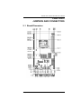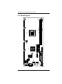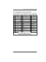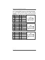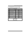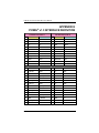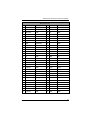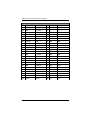
1
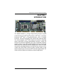
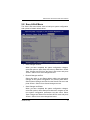
Product User Manual $;,207(. and enterprise branch and head offices www.enochsystems.com SHB108 1-877-722-1116 [email protected] Copyright © 2013 Enoch Systems, LLC, Enoch Systems and the Enoch Systems logo are trademarks or registered trademarks of Enoch Systems, LLC and/or its affiliates in the U.S. and other countries. Third-party trademarks mentioned are the property of their respective owners. All rights reserved. SHB108 Series LGA1155 Socket Intel® Xeon® / Intel Core™i7 / Core™i5 / Core™i3 / Processor PICMG® 1.3 Full-Size CPU Card User’s Manual Disclaimers This manual has been carefully checked and believed to contain accurate information. Axiomtek Co., Ltd. assumes no responsibility for any infringements of patents or any third party’s rights, and any liability arising from such use. Axiomtek does not warrant or assume any legal liability or responsibility for the accuracy, completeness or usefulness of any information in this document. Axiomtek does not make any commitment to update the information in this manual. Axiomtek reserves the right to change or revise this document and/or product at any time without notice. No part of this document may be reproduced, stored in a retrieval system, or transmitted, in any form or by any means, electronic, mechanical, photocopying, recording, or otherwise, without the prior written permission of Axiomtek Co., Ltd. Caution If you replace wrong batteries, it causes the danger of explosion. It is recommended by the manufacturer that you follow the manufacturer’s instructions to only replace the same or equivalent type of battery, and dispose of used ones. Copyright 2011 Axiomtek Co., Ltd. All Rights Reserved November 2011, Version A1 Printed in Taiwan II ESD Precautions Computer boards have integrated circuits sensitive to static electricity. To prevent chipsets from electrostatic discharge damage, please take care of the following jobs with precautions: Do not remove boards or integrated circuits from their anti-static Packaging until you are ready to install them. Before holding the board or integrated circuit, touch an unpainted portion of the system unit chassis for a few seconds. It discharges static electricity from your body. Wear a wrist-grounding strap, available from most electronic Component stores, when handling boards and components. Trademarks Acknowledgments Axiomtek is a trademark of Axiomtek Co., Ltd. ® Windows is a trademark of Microsoft Corporation. AMI are trademarks of American Megatrend Inc. IBM, PC/AT, PS/2, VGA are trademarks of International Business Machines Corporation. ® Intel® Core™ Xeon Desktop Processor, Intel® Core™ i3 LGA1155 Desktop Processor, Intel® Core™ i5 LGA1155 Desktop Processor, Intel® Core™ i7 LGA1155 Desktop Processor, are trademarks of Intel Corporation Winbond is a trademark of Winbond Electronics Corp. Other brand names and trademarks are the properties and registered brands of their respective owners. III Table of Contents CHAPTER 1 INTRODUCTION ..................................................................... 1 1.1 Specifications....................................................................... 2 1.2 Utilities Supported................................................................ 4 CHAPTER 2 JUMPERS AND CONNECTORS ............................................ 5 2.1 Board Dimension ................................................................. 5 2.2 Board Layout ....................................................................... 6 2.3 Jumper Settings ................................................................... 7 2.3.1 COM1 Mode Select Jumpers for RS232/422/485 (JP2, JP3, JP4) ..................................................................................... 7 2.3.2 Audio Ampliier Jumper (JP1) ............................................... 8 2.3.3 Clear ME Jumper (JP6) ....................................................... 8 2.3.4 PS/2 Power Jumper (JP7) ................................................... 8 2.4 Connectors .......................................................................... 9 2.4.1 SMBUS Connector (CN1) .................................................. 10 2.4.2 Floppy Disk Port Connector (CN2) .................................... 11 2.4.3 Internal USB Connectors (CN3,CN4,CN5,CN6) ................ 12 2.4.4 LAN2 LED Connectors (CN7) ............................................ 13 2.4.5 LAN1 LED Connectors (CN8) ............................................ 13 2.4.6 DB15 CRT Connector (CN10) Co-layout with CN11 .......... 14 2.4.7 Display Port Connector (CN11) Co-layout with CN10........ 14 2.4.8 Front Panel Connector (CN12) .......................................... 15 2.4.9 PS/2 Keyboard, Mouse Connectors (CN13, CN14) ........... 16 2.4.10 External USB Port Connectors (CN17, CN18) .................. 16 2.4.11 RS232/422/485 Pin Assignment (COM1) .......................... 17 2.4.12 COM Port RS-232 Pin Assignment (COM2) ...................... 18 ® 2.4.13 Intel HD Audio Digital Header (AUDIO1) ......................... 18 2.4.14 ATX 8 Pin 12V IN Connector (ATX1) ................................. 19 2.4.15 A CPU fan is always needed for cooling CPU heat (FAN1)19 2.4.16 System & Auxiliary Fan Connectors (FAN2, FAN3) .......... 19 2.4.17 Ethernet RJ-45 Connectors (LAN1, LAN2) ........................ 20 2.4.18 Parallel Port Connector (PRINT1) Print Port Connector .... 21 2.4.19 SATA Connectors (SATA1 ,SATA2 ,SATA3 ,SATA4 ,SATA5 , SATA6) .............................................................................. 22 CHAPTER 3 HARDWARE INSTALLATION .............................................. 23 3.1 Installing the Processor ..................................................... 23 3.2 Installing the Memory ......................................................... 32 CHAPTER 4 HARDWARE DESCRIPTION ................................................ 33 4.1 Microprocessors ................................................................ 33 4.2 BIOS .................................................................................. 33 4.3 System Memory ................................................................. 33 IV 4.4 4.5 I/O Port Address Map ........................................................ 34 Interrupt Controller (IRQ) Map ........................................... 35 CHAPTER 5 AMI BIOS UTILITY ................................................................ 37 5.1 Starting .............................................................................. 37 5.2 Navigation Keys ................................................................. 37 5.3 Main Menu ......................................................................... 39 5.4 Advanced Menu ................................................................. 40 5.5 Chipset Menu ..................................................................... 50 5.6 Boot Menu ......................................................................... 54 5.7 Security Menu .................................................................... 56 5.8 Save & Exit Menu .............................................................. 57 APPENDIX A WATCHDOG TIMER ........................................................... 60 Watchdog Timer Setting ....................................................................... 60 APPENDIX B PCI IRQ ROUTING ............................................................. 62 ® PICMG PCI IRQ Routing ..................................................................... 62 APPENDIX C CONFIGURING SATA FOR RAID FUNCTION ................... 63 APPENDIX D D.1 D.2 D.3 D.4 iAMT SETTINGS ................................................................ 76 Entering MEBx ................................................................... 76 Set & Change Password .................................................... 77 Intel® iAMT Settings .......................................................... 79 iAMT Web Console ............................................................ 84 ® APPENDIX E PICMG v1.3 INTERFACE DEFINITION ............................ 86 V MEMO: VI SHB108 LAG1155 Full-Size SBC User’s Manual CHAPTER 1 INTRODUCTION The SHB108 PICMG ® 1.3 full-size Single Board Computer supports ® ® ® LAG1155 socket for Intel Xeon processor, Intel Core™ i3 Desktop ® Processor, Intel Core™ i5 Desktop Processor, Core™ i7 Desktop Processor with 32nm technology and Transfer Rate 1066/1333 MHz. ® The board integrates Intel C206 chipset that delivers outstanding system performance through high-bandwidth interfaces, multiple I/O functions for interactive applications and various embedded computing solutions. There are two 240-pin DDR3 DIMM sockets for dual channel DDR3 1066/1333, maximum memory capacity up to 16GB. The board also features dual Gigabit Ethernet, two SATA-6.0Gb/s and four SATA3.0Gb/s and SATA RAID 0/1/5/10 by PCH. Fourteen USB 2.0 high ® speed compliant ports and built-in Intel HD Audio Digital Header can achieve the best stability and reliability for industrial applications. Introduction 1 SHB108 LAG1155 Full-Size SBC User’s Manual 1.1 Specifications CPU Intel® Core™ i3 Desktop Processor Intel® Core™ i5 Desktop Processor Intel® Core™ i7 Desktop Processor Intel® Xeon® Processor System Chipset Intel® C206 CPU Socket LAG1155 Socket DRAM Transfer Rate 1066/1333 MHz BIOS AMI BIOS via SPI interface with socket System Memory Two 240-pin DDR3 1066/1333 DIMM sockets Maximum up to 16GB DDR3 memory(1*8GB per channel) L1, L2, L3 Cache: integrated in CPU Onboard Multi-I/O 2 Parallel Port: one 26-pin 2.54-pitch box-header, SPP/EPP/ECP supported Serial Port: one for RS-232/422/485 with 10-pin, 2.54-pitch boxheader (COM1) and one port for RS-232 with 10-pin, 2.54-pitch box-header (COM2) Floppy controller: one 34-pin, 2.54-pitch box-header supports two drives (1.44MB for each) Introduction SHB108 LAG1155 Full-Size SBC User’s Manual USB Interface Ten USB ports compliant with USB Spec. Rev. 2.0 (2 ports on rear I/O, 8 ports on board, 4 ports to SHB connector-C golden fingers) Onboard Graphic Intel® Arrandale integrated Graphic processing unit processors which goes with C206 chipset with,VGA,DisplayPort (co-lay with VGA) Memory Size --Intel® DVMT 5.0 supported; preallocated memory for frame buffer option as OS option: Windows XP: * For Total System Memory < 1GB, Graphics sharing memory = 128 MB Maximum; * For 1 GB to 1.5 GB Total System Memory, Graphics sharing memory = 512 MB Maximum; * For 1.5 GB to 2 GB Total System Memory, Graphics sharing memory = 768 MB Maximum; * For 2 GB and Above Total System Memory, Graphics sharing memory = 1GB Maximum. Windows Vista: * Graphics sharing memory max to 0.5* (OS Ram Size – 512) Resolution -- Analog output -- the analog port utilizes an integrated 400MHz 24-bit RAMDAC that can directly drive a standard progressive scan analog monitor up to a resolution of 2048x1536 pixels with 32-bit color at 75 Hz Analog Output Interface -- CRT from DAC output via 15-pin DSub connector on the edge; CRT always ON supported Ethernet The LAN1/LAN2 are Intel 82579LM with iAMT 7.0 / Intel 82574L Ethernet controller support 10/100/1000 Mb/s Serial ATA Two Serial ATA-6Gb/s and Four Serial ATA-3Gb/s performance and SATA RAID 0/1/5/10 by C206 Introduction 3 SHB108 LAG1155 Full-Size SBC User’s Manual Audio 10-pin 2.54 pin-header (Intel® HD Audio Digital Header) Hardware Monitoring Monitoring temperatures, voltages, and cooling fan status Watchdog Timer Reset Supported (1-255 level) Dimensions 338mm x 126mm Expansion interface: 1 PCI-E x16 1 PCI-E x4(or 4 PCI-E x1) 4 PCI NOTE: All specifications and images are subject to change without notice. 1.2 Utilities Supported ® Intel C206 Utility and Drivers VGA Drivers Ethernet Utility and Drivers RAID Utility iAMT Utility and Drivers TPM Utility 4 Introduction SHB108 LAG1155 Full-Size SBC User’s Manual CHAPTER 2 JUMPERS AND CONNECTORS 2.1 Board Dimension Jumpers And Connectors 5 SHB108 LAG1155 Full-Size SBC User’s Manual 2.2 Board Layout ATX1 240 33 33 31 31 29 27 29 25 27 23 25 21 23 19 21 17 19 15 17 13 15 11 13 9 11 9 7 7 5 5 3 3 1 1 AW U R 1 CN1FAN2FAN3COM2 BK 121 121 JP6 CN6 CN2 LAN1 10 2 10 2 9 1 9 1 A Y C C G C A Y A A G C LAN2 AUDIO JP1 1 1 C CN3 C N CN11 N 4 CN12 5 SATA1SATA3SATA5 COM1 PRINT1 SATA2 SATA4SATA6 A BU L N BU AY AU AN AR AL AG AJ AC AE AA J U21 CN14 CN18 JP7 CN17 CN13 CN10 W E G C A AY DIMM2 35 35 AK 240 37 37 1 20 57 50 40 30 20 10 1 DIMM1 39 39 Y Jumpers And Connectors 6 40 40 U23 FAN1 K A SHB108 LAG1155 Full-Size SBC User’s Manual 2.3 Jumper Settings Proper jumper settings configure the SHB108 to meet your application purpose. We are herewith listing a summary table of all jumpers and default settings for onboard devices, respectively. Jumper Description Jumper Setting JP2 COM1 Mode Selection : RS-232 Short 3-5 , 4-6 JP3 COM1 Mode Selection : RS-232 Short 3-5 , 4-6 JP4 COM1 Mode Selection : RS-232 Short 1-2 JP1 Audio Amplifier Selection : Disable Short 1-3 , 2-4 JP6 Clear ME : Normal Short 1-2 JP7 PS/2 Power Selection : 5VSBY Short 2-3 2.3.1 COM1 Mode Select Jumpers for RS232/422/485 (JP2, JP3, JP4) These jumpers select the COM1 port’s communication mode to operate RS-232 or RS-422/485 Function Jumper Setting JP2 JP3 JP4 RS-232 (Default) RS-422 RS-485 Jumpers And Connectors 7 SHB108 LAG1155 Full-Size SBC User’s Manual 2.3.2 Audio Ampliier Jumper (JP1) Function Jumper Setting Disable (Default) Enable 2.3.3 Clear ME Jumper (JP6) You may need to use this jumper to clear the ME if incorrect ME settings. Function Jumper Setting Normal (Default) Clear ME 2.3.4 PS/2 Power Jumper (JP7) You may need to ues this jumper to into S3 situation in WinXP. Function Jumper Setting 5V 5VSBY (Default) 8 Jumpers And Connectors SHB108 LAG1155 Full-Size SBC User’s Manual 2.4 Connectors Connectors connect this board with other parts of the system. Loose or improper connection might cause problems. Make sure all connectors are properly and firmly connected. Here is a summary table shows you all connectors on the board. Connector Label SMBUS CN1 Floppy Connecter CN2 USB Port 6/7 CN3 USB Port 8/9 CN4 USB Port 12/13 CN5 USB Port 10/11 CN6 LAN2 External LED CN7 LAN1 External LED CN8 VGA Port CN10 Display Port (BOM Option) CN11 Axiomtek Front Panel CN12 Keyboard CN13 Mouse CN14 USB Port 5 CN17 USB Port 4 CN18 COM1 Connector COM1 COM2 Connector COM2 Audio Connector AUDIO1 ATX Connecter ATX1 CPU FAN FAN1 SYS FAN FAN2 AUX FAN FAN3 RJ45 (WG82579LM) LAN1 Jumpers And Connectors 9 SHB108 LAG1155 Full-Size SBC User’s Manual Connector RJ45 (WG82574L) Label LAN2 Print Connecter PRINT1 SATA 0 6.0Gb(SATA3) SATA1 SATA 1 6.0Gb(SATA3) SATA2 SATA Port 2 SATA3 SATA Port 5 SATA4 SATA Port 3 SATA5 SATA Port 4 SATA6 2.4.1 SMBUS Connector (CN1) Connector SMBUS CN1 is for SMBUS interface support. Pin 10 Signal 1 CLOCK 2 N.C 3 GND 4 DATA 5 +5V Jumpers And Connectors SHB108 LAG1155 Full-Size SBC User’s Manual 2.4.2 Floppy Disk Port Connector (CN2) The board provides a 34-pin header type connector, CN2, supporting up to two floppy drives. The floppy drives may be any one of the following types: 5.25" 360KB/1.2MB and 3.5" 720KB/1.44MB/2.88MB. Pin Signal Pin Signal Pin Signal 1 GND 2 Drive Density Select 3 GND 4 No connector 5 GND 6 No connector 7 GND 8 Index# 9 GND 10 Motor enable A# 11 GND 12 No connector 13 GND 14 Drive select A# 15 GND 16 No connector 17 GND 18 Direction# 19 GND 20 STEP# 21 GND 22 Write data# 23 GND 24 Write gate# 25 GND 26 Track 0 # 27 GND 28 Write protect# 29 No connector 30 Read data# 31 GND 32 Head selection# 33 No connector 34 Disk change# Jumpers And Connectors 11 SHB108 LAG1155 Full-Size SBC User’s Manual 2.4.3 Internal USB Connectors (CN3,CN4,CN5,CN6) The 10-pin standard Universal Serial Bus (USB) connectors, CN3/4/5/6, on this board are for installing versatile USB interface peripherals. Pin Signal Pin Signal 1 USB_PWR 2 USB_PWR 3 USB6- 4 USB7- 5 USB6+ 6 USB7+ 7 GND 8 GND CN3 10 GND Pin Signal Pin Signal 1 USB_PWR 2 USB_PWR 3 USB8- 4 USB9- 5 USB8+ 6 USB9+ 7 GND 8 GND CN4 10 GND Pin Signal Pin Signal 1 USB_PWR 2 USB_PWR 3 USB12- 4 USB13- 5 USB12+ 6 USB13+ 7 GND 8 GND CN5 10 GND 12 Jumpers And Connectors SHB108 LAG1155 Full-Size SBC User’s Manual Pin Signal Pin Signal 1 USB_PWR 2 USB_PWR 3 USB10- 4 USB11- 5 USB10+ 6 USB11+ 7 GND 8 GND CN6 10 GND 2.4.4 LAN2 LED Connectors (CN7) Pin Signal 1 + 3.3V 2 LINK_ACT LED(-) 3 100, Low Active 4 +3.3V 5 1000, Low Active 2.4.5 LAN1 LED Connectors (CN8) Pin Signal 1 + 3.3V 2 LINK_ACT LED(-) 3 4 5 100, Low Active +3.3V 1000, Low Active Jumpers And Connectors 13 SHB108 LAG1155 Full-Size SBC User’s Manual 2.4.6 DB15 CRT Connector (CN10) Co-layout with CN11 CN10 is a DB15 connector commonly used for the CRT Monitor. Pin Signal Pin Signal Pin Signal 1 Red 2 Green 3 Blue 4 N.C 5 GND 6 DETECT 7 GND 8 GND 9 VCC 10 GND 11 N.C 12 DDC DATA 13 Horizontal Sync 14 Vertical Sync 15 DDC CLK 5 1 10 15 6 11 2.4.7 Display Port Connector (CN11) Co-layout with CN10 CN11 is a Standard Display Port Connector co-layout with CN10. Pin 14 Signal 1 DPB_LANE0 2 GND 3 DPB_LANE0# 4 DPB_LANE1 5 GND 6 DPB_LANE1# 7 DPB_LANE2 8 GND 9 DPB_LANE2# 10 DPB_LANE3 11 GND CN24 Jumpers And Connectors SHB108 LAG1155 Full-Size SBC User’s Manual Pin Signal 12 DPB_LANE3# 13 Detect Pin 14 GND 15 DPB_AUX 16 GND 17 DPB_AUX# 18 DPB_HPDE 19 GND 20 +3.3V 2.4.8 Front Panel Connector (CN12) Power LED This 3-pin connector denoted as Pin 1 and Pin 5 connects the system power LED indicator to such a switch on the case. Pin 1 is assigned as +, and Pin 5 as -. The Power LED lights up when the system is powered ON. Pin 3 is defined as GND. External Speaker and Internal Buzzer Connector Pin 2, 4, 6 and 8 can be connected to the case-mounted speaker unit or internal buzzer. While connecting the CPU card to an internal buzzer, please short pins 2-4; while connecting to an external speaker, you need to set pins 2-4 to Open and connect the speaker cable to pin 8 (+) and pin 2 (-). ATX Power On/Off Button This 2-pin connector denoted as Pin 9 and 10 connects the front panel’s ATX power button to the CPU card, which allows users to control ATX power supply to be power on/off. Jumpers And Connectors 15 SHB108 LAG1155 Full-Size SBC User’s Manual System Reset Switch Pin 11 and 12 can be connected to the case-mounted reset switch that reboots your computer instead of turning OFF the power switch. It is a better way to reboot your system for a longer life of the system’s power supply. HDD Activity LED This connection is linked to hard drive activity LED on the control panel. LED flashes when HDD is being accessed. Pin 13 and 14 connect the hard disk drive to the front panel HDD LED, Pin 13 assigned as -, and Pin 14 as +. 2.4.9 PS/2 Keyboard, Mouse Connectors (CN13, CN14) The board provides theMouse (CN14)/ Keyboard (CN13) interface with a 5-pin connecter. Pin Signal 1 Clock 2 DATA 3 No connector 4 GND 5 +5V / 5VSBY 2.4.10 External USB Port Connectors (CN17, CN18) The 4-pin standard Universal Serial Bus (USB) port connector on the board is for the installation of peripherals supporting the USB interface. Pin 16 Signal 1 USB_POWER 2 USB - 3 USB + 4 GND 1 2 3 4 Jumpers And Connectors SHB108 LAG1155 Full-Size SBC User’s Manual 2.4.11 RS232/422/485 Pin Assignment (COM1) The serial interface for the board consists of COM1 support for RS232 and COM1 for RS-232/RS-422/RS-485. Pin Signal Name RS-232 RS-422 RS-485 1 Data Carrier Detect (DCD) TX- DATA- 2 Data Set Ready (DSR) No connector No connector 3 Receive Data (RXD) TX+ DATA+ 4 Request to Send (RTS) No connector No connector 5 Transmit Data (TXD) RX+ No connector 6 Clear to Send (CTS) No connector No connector 7 Data Terminal Ready (DTR) RX- No connector 8 Ring Indicator (RI) No connector No connector 9 Ground (GND) GND GND 10 Disconnect(NI) NI NI Jumpers And Connectors 17 SHB108 LAG1155 Full-Size SBC User’s Manual 2.4.12 COM Port RS-232 Pin Assignment (COM2) COM2 Serial Port 10-pin (Box-header) Connector Pin Assignment list Pin Signal Pin Signal 1 Data Carrier Detect (DCD) 2 Data Set Ready (DSR) 3 Receive Data (RXD) 4 Request to Send (RTS) 5 Transmit Data (TXD) 6 Clear to Send (CTS) 7 Data Terminal Ready (DTR) 8 Ring Indicator (RI) 9 Ground (GND) 10 Disconnect(NI) 2.4.13 Intel® HD Audio Digital Header (AUDIO1) Pin 18 Signal Pin Signal 1 MIC IN 2 GND 3 LINE_IN_L 4 GND 5 LINE_IN_R 6 GND 7 LINE_OUT_L 8 GND 9 LINE_OUT_R 10 GND Jumpers And Connectors SHB108 LAG1155 Full-Size SBC User’s Manual 2.4.14 ATX 8 Pin 12V IN Connector (ATX1) You can connect it to the ATX12V power supply for CPU Core Voltage. Pin Signal 1 GND 2 GND 3 GND 4 GND 5 +12V 6 +12V 7 +12V 8 +12V 2.4.15 A CPU fan is always needed for cooling CPU heat (FAN1) The CPU fan connector FAN1 provides power to the CPU fan. Pin Signal 1 Ground 2 +12V 3 Rotation Detection 4 Speed Control 2.4.16 System & Auxiliary Fan Connectors (FAN2, FAN3) You can connect the system cooling fan cable to FAN2/FAN3 for system cooling fan power. Pin Signal 1 GND 2 +12V 3 Rotation Detection Jumpers And Connectors 19 SHB108 LAG1155 Full-Size SBC User’s Manual 2.4.17 Ethernet RJ-45 Connectors (LAN1, LAN2) The RJ-45 connectors LAN1 and LAN2 are for Ethernet. To connect the board to 100-Base-T or 1000-Base-T hub, just plug one end of the cable into LAN1 and connect the other end (phone jack) to a 100Base-T hub or 1000-Base-T hub. Pin 20 Signal 1 Tx+ (Data transmission positive) 2 Tx- (Data transmission negative) 3 Rx+(Data reception positive) 4 RJ-1(For 1000 base T-Only) 5 RJ-1(For 1000 base T-Only) 6 Rx- (Data reception negative) 7 RJ-1(For 1000 base T-Only) 8 RJ-1(For 1000 base T-Only) A Active LED B Speed LED A B 87654321 Jumpers And Connectors SHB108 LAG1155 Full-Size SBC User’s Manual 2.4.18 Parallel Port Connector (PRINT1) Print Port Connector This board has a multi-mode parallel port to support: Standard Mode: IBM PC/XT, PC/AT and PS/2 are compatible with bi-directional parallel port. Enhanced Mode: Enhance parallel port (EPP) is compatible with EPP 1.7 and EPP 1.9 (IEEE 1284 compliant). High Speed Mode: Microsoft and Hewlett Packard extended capabilities port (ECP) is IEEE 1284 compliant. Pin Signal Pin Signal 1 Strobe# 2 Auto Form Feed# 3 Data 0 4 Error# 5 Data 1 6 Initialize# 7 Data 2 8 Printer Select In# 9 Data 3 10 GND 11 Data 4 12 GND 13 Data 5 14 GND 15 Data 6 16 GND 17 Data 7 18 GND 19 Acknowledge# 20 GND 21 Busy 22 GND 23 Paper Empty# 24 GND 25 Printer Select 26 N.C Jumpers And Connectors 21 SHB108 LAG1155 Full-Size SBC User’s Manual 2.4.19 SATA Connectors (SATA1 ,SATA2 ,SATA3 ,SATA4 ,SATA5 , SATA6) These SATA connectors are for high-speed SATA interface ports and they can be connected to hard disk devices. Pin 22 Signal 1 GND 2 SATA_TX+ 3 SATA_TX- 4 GND 5 SATA_RX- 6 SATA_RX+ 7 GND Jumpers And Connectors SHB108 LAG1156 Full-Size SBC User’s Manual CHAPTER 3 HARDWARE INSTALLATION ® Before installing the processor, please access Intel website for more detail information Processor Integration Video (LGA1155): http://www.intel.com/support/tw/processors/sb/CS-030860.htm . 3.1 Installing the Processor The LGA1155 processor socket comes with a cover to protect the processor. Please install the processor into the CPU socket step by step as below: Step1 Opening the Socket: Disengage load lever by releasing down and out on the hook. This will clear retention tab. Rotate load lever to open position at approximately 135°. Rotate load plate to open position at approximately 150°. NOTE: Apply pressure to corner with right-hand thumb when opening or closing load lever - otherwise lever will bounce back (as a mouse trap) causing bent contacts. Hardware Installation 23 SHB108 LAG1155 Full-Size SBC User’s Manual Step2 Removing the socket protective cover: Place thumb against the front edge of the protective cover and rest index finger on the rear grip to maintain control of the cover. Lift the front edge of the protective cover to disengage from the socket. Keep control of the cover by holding the rear grip with index finger. Lift protective cover away from the socket, being careful not to touch the electrical contacts. NOTE: Vertical removal is NOT recommended, as it requires higher force and can lead to socket contact damage. Caution: Never Touch Fragile Socket Contacts to Avoid Damage and Do Not Touch Processor Sensitive Contacts at Any Time During Installation. 24 Hardware Installation SHB108 LAG1156 Full-Size SBC User’s Manual Step3 Processor installation: Lift processor package from shipping media by grasping the substrate edges. Scan the processor package gold pads for any presence of foreign material. If necessary, the gold pads can be wiped clean with a soft lint-free cloth and isopropyl alcohol. Scan the processor package gold pads for any presence of foreign material. If necessary, the gold pads can be wiped clean with a soft lint-free cloth and isopropyl alcohol. Locate connection 1 indicator on the processor which aligns with connection 1 indicator chamfer on the socket, and notice processor keying features that line up with posts along socket walls. Hardware Installation 25 SHB108 LAG1155 Full-Size SBC User’s Manual Grasp the processor with thumb and index finger along the top and bottom edges. (Do not touch the Orientation Notches.) The socket will have cutouts for your fingers to fit into (see image below). Carefully place the processor into the socket body vertically (see image below). NOTE: Tilting or roughly shifting it into place can damage socket contacts. Caution: Do not use a vacuum pen for installation. 26 Hardware Installation SHB108 LAG1156 Full-Size SBC User’s Manual Verify that package is within the socket body and properly connected to orientation keys. Close the socket (see image below): A. Gently lower the load plate. B. Make sure load plate's front edge slides under the shoulder screw cap as the lever is lowered. C. Latch the lever under the top plate's corner tab, being cautious not to damage the motherboard with the tip of the lever. Hardware Installation 27 SHB108 LAG1155 Full-Size SBC User’s Manual Close the socket (see image below): A Gently lower the load plate. B Make sure load plate's front edge slides under the shoulder screw cap as the lever is lowered. C Catch the lever under the top plate's corner tab being cautious not to damage the motherboard with the tip of the lever. 28 Hardware Installation SHB108 LAG1156 Full-Size SBC User’s Manual Step4 Fan heatsink handling: 1. Orientate the CPU cooling fan to fixing holes on the board. 2. Screw the CPU cooling fan onto the board. 3. Make sure the CPU fan is plugged to the CPU fan connector. Hardware Installation 29 SHB108 LAG1155 Full-Size SBC User’s Manual Step5 Removing the processor: Open the socket: A. Disengage the load lever. B. Open the load plate. Remove the Processor package, holding along the top and bottom edges, or by using a vacuum pen. Maintain Processor horizontal and remove Processor with a vertical motion to avoid damaging the socket contacts. Place the processor in a specially designed tray or ESD retainer for storage. Do not place directly on table resting on gold lands. Assemble LGA1155 socket protective cover: A Hold protective cover at 45 degree angle to the LGA1155 Socket B Carefully lower protective cover on hinge side first, to contact with the outside wall of the LGA1155 Socket: 30 Hardware Installation SHB108 LAG1156 Full-Size SBC User’s Manual i. Engage protective cover retention features to outside of LGA1155 Socket, AND align 2 cover corners to socket corners (This step is critical to avoid Bent Contact Damage!) ii. Lower protective cover to attach to the LGA1155 Socket on Shoulder screw side Perform Visual and Tactile verification that protective cover is properly seated in the LGA1155 Socket: *Hold cover and move gently "side to side" to feel the play within the cover and the LGA1155 Socket. Close the socket load plate and engage the load lever (see image below). Hardware Installation 31 SHB108 LAG1155 Full-Size SBC User’s Manual 3.2 Installing the Memory The board supports four 240-pin DDR3 DIMM memory sockets with maximum memory capacity up to 16GB. Please follow steps below to install the memory modules: Push down latches on each side of the DIMM socket. Align the memory module with the socket that notches of memory module must match the socket keys for a correct installation. Install the memory module into the socket and push it firmly down until it is fully seated. The socket latches are levered upwards and clipped on to the edges of the DIMM. Install any remaining DIMM modules. 32 Hardware Installation SHB108 LAG1156 Full-Size SBC User’s Manual CHAPTER 4 HARDWARE DESCRIPTION 4.1 Microprocessors ® ® ® ™ ™ The SHB108 Series supports Intel Xeon / Intel Core i7 / Core i5 / ™ Core i3 / processors, which make your system operated under ® Windows XP and Linux environments. The system performance depends on the microprocessor. Make sure all correct settings are arranged for your installed microprocessor to prevent the CPU from damages. 4.2 BIOS The SHB108 Series uses AMI Plug and Play BIOS with a single 32Mbit SPI Flash. 4.3 System Memory The SHB108 Series supports two 240-pin DDR3 DIMM sockets for a maximum memory of 16GB DDR3 SDRAMs. The memory module can come in sizes of 2GB and 4GB or 1*8GB per channel. Hardware Description 33 SHB108 LAG1155 Full-Size SBC User’s Manual 4.4 I/O Port Address Map ® ™ ™ ™ The Intel Core i7 / Core i5 / Core i3 processors can communicate via I/O ports. There are total 1KB port addresses available for assignment to other devices via I/O expansion cards Address 000-01F 020-02D, 024-025 028-029, 02C-02D 02E-02F 030-031, 034-035 038-039, 03C-03D 040-043, 050-053 060 061 062-066 070-077 080-091 092 093-09F 0A0-0BF 0C0-0DF 0F0 0F8-0FF 170-177 1F0-1F7 376 378-37F 380-38F 3A0-3AF 3B0-3BF 3C0-3CF 3D0-3DF 3F6 3F8-3FF 2F8-2FF 34 Devices DMA controller #1 Interrupt controller #1 Forwarded to LPC(LPC Super I/O ) Interrupt controller #2 Timer/Counter (8254) Forwarded to LPC (Microcontroller) NMI Forwarded to LPC (Microcontroller) Real time clock, NMI DMA page register Processor I/F(Reset Generator) DMA page register Interrupt controller #2 DMA controller #2 Processor I/F Math processor Forward to SATA (SATA Controller) Forward to SATA (SATA Controller) Forward to SATA(SATA Controller) Parallel Port (LPT) SDLC #2 SDLC #1 MDA video card EGA card CGA card Forward to SATA(SATA Controller) Serial port #1 (COM1) Serial port #2 (COM2) Hardware Description SHB108 LAG1156 Full-Size SBC User’s Manual 4.5 Interrupt Controller (IRQ) Map The SHB108 Series is a 100% PC compatible control board. It consists of 16 interrupt request lines, and four out of them can be programmable. The mapping list of the 16 interrupt request lines is shown as the following table. IRQ Parity check error IRQ0 System Timer Output IRQ1 Keyboard IRQ2 Interrupt rerouting from IRQ8 through IRQ15 IRQ3 Serial port #2 IRQ4 Serial port #1 IRQ5 PCI Device Share IRQ6 Floppy Disk Controller IRQ7 Parallel port IRQ8 Real time clock IRQ9 ACPI Controller IRQ10 PCI Device Share IRQ11 PCI Device Share IRQ12 PS/2 Mouse IRQ13 Math coprocessor IRQ14 SATA Primary (Legacy Mode) IRQ15 SATA Secondary (Legacy Mode) 3C0-3CF EGA card 3D0-3DF CGA card 3F6 Forward to SATA(SATA Controller) 3F8-3FF Serial port #1 (COM1) 2F8-2FF Serial port #2 (COM2) Hardware Description 35 SHB108 LAG1155 Full-Size SBC User’s Manual MEMO: : 36 Hardware Description SHB108 LAG1156 Full-Size SBC User’s Manual CHAPTER 5 AMI BIOS UTILITY This chapter provides users with detailed description how to set up basic system configuration through the AMIBIOS8 BIOS setup utility. 5.1 Starting To enter the setup screens, follow the steps below: Turn on the computer and press the <F2> key immediately. After you press the <F2> key, the main BIOS setup menu displays. You can access the other setup screens from the main BIOS setup menu, such as the Chipset and Power menus. 5.2 Navigation Keys The BIOS setup/utility uses a key-based navigation system called hot keys. Most of the BIOS setup utility hot keys can be used at any time during the setup navigation process. These keys include <F1>, <F2>, <Enter>, <ESC>, <Arrow> keys, and so on. NOTE: Some of navigation keys differ from one screen to another. AMI BIOS Utility 37 SHB108 LAG1155 Full-Size SBC User’s Manual Left/Right Up/Down The Left <Arrow> keys allow you to select a setup screen. The Up and Down <Arrow> keys allow you to select a setup screen or sub-screen. + Plus/Minus The Plus and Minus <Arrow> keys allow you to change the field value of a particular setup item. Tab 38 The <Tab> key allows you to select setup fields. F1 The <F1> key allows you to display the General Help screen. F2 The <F2> key allows you to Load Previous Values. F3 The <F3> key allows you to Load Optimized Defaults. F4 The <F4> key allows you to save any changes you have made and exit Setup. Press the <F4> key to save your changes. Esc The <Esc> key allows you to discard any changes you have made and exit the Setup. Press the <Esc> key to exit the setup without saving your changes. Enter The <Enter> key allows you to display or change the setup option listed for a particular setup item. The <Enter> key can also allow you to display the setup sub- screens. AMI BIOS Utility SHB108 LAG1156 Full-Size SBC User’s Manual 5.3 Main Menu When you first enter the Setup Utility, you will enter the Main setup screen. You can always return to the Main setup screen by selecting the Main tab. There are two Main Setup options. They are described in this section. The Main BIOS Setup screen is shown below. System Date/Time Use this option to change the system date and time. Highlight System Date or System Time using the <Arrow> keys. Enter new values through the keyboard. Press the <Tab> key or the <Enter> keys to move between fields. The date must be entered in MM/DD/YY format. The time is entered in HH:MM:SS format. AMI BIOS Utility 39 SHB108 LAG1155 Full-Size SBC User’s Manual 5.4 Advanced Menu Launch PXE OpROM Use this item to enable or disable the Boot ROM function of the onboard LAN chip when the system boots up. Launch Storage OpROM This item can set enable or disable the storage device option ROM with CF device. The Advanced menu also allows users to set configuration of the CPU and other system devices. You can select any of the items in the left frame of the screen to go to the sub menus: ACPI Settings Trusted Computing CPU Configuration SATA Configuration Intel IGD SWSCI OpRegion USB Configuration Super IO Configuration H/W Monitor AMT Configuration For items marked with “”, please press <Enter> for more options. 40 AMI BIOS Utility SHB108 LAG1156 Full-Size SBC User’s Manual ACPI Settings You can use this screen to select options for the ACPI Configuration, and change the value of the selected option. A description of the selected item appears on the right side of the screen. ACPI Sleep State Allow you to select the Advanced Configuration and Power Interface (ACPI) state to be used for system suspend. Here are the options for your selection, S1 (CPU Stop Clock), S3 (Suspend to RAM) and Suspend Disable AMI BIOS Utility 41 SHB108 LAG1155 Full-Size SBC User’s Manual Trusted Computing You can use this screen to select options for the Trusted Computing, and change the value of the selected option. A description of the selected item appears on the right side of the screen. TPM SUPPORT Use this item to control the Trusted Platform Module (TPM) function. 42 AMI BIOS Utility SHB108 LAG1156 Full-Size SBC User’s Manual CPU Configuration This screen shows the CPU Configuration, and you can change the value of the selected option. Hyper-threading Use Hyper-threading function to enable or disable the CPU Hyper-threading. Active Processor Cores This feature controls the number of cores to enable in each processor package. Intel Virtualization Technology Allows a hardware platform to run multiple operating systems separately and simultaneously, enabling one system to virtually function as several systems. AMI BIOS Utility 43 SHB108 LAG1155 Full-Size SBC User’s Manual SATA Configuration You can use this screen to select options for the SATA Configuration, and change the value of the selected option. A description of the selected item appears on the right side of the screen. SATA Mode Use this item to choose the SATA operation mode. Here are the options for your selection, IDE Mode, AHCI Mode and RAID Mode. Serial-ATA Controller 0 Use this item to control the onboard SATA controller. Here are the options for your selection, Compatible, Enhanced and Disable. Serial-ATA Controller 1 Use this item to control the onboard SATA controller. Here are the options for your selection, Enhanced and Disabled. 44 AMI BIOS Utility SHB108 LAG1156 Full-Size SBC User’s Manual Intel IGD SWSCI OpRegion The Intel IGD SWSCI OpRegion allows users to change the integrated graphic device settings. DVMT/FIXED Memory Allow you to allocate a fixed amount of system memory as graphics memory. Here are the options for your selection, 128MB, 256MB and Maximum DVMT. AMI BIOS Utility 45 SHB108 LAG1155 Full-Size SBC User’s Manual USB Configuration You can use this screen to select options for the USB Configuration, and change the value of the selected option. A description of the selected item appears on the right side of the screen. Legacy USB Support Use the legacy usb support bios option to enable USB mouse and USB keyboard support. Normolly if this option is not enable, any attach usb mouse or USB keyboard does not become available until a USB compatible operation system is full booted with all USB drivers loaded.When this option is enable, any attach USB mouse or USB keyboard can control the system even when there is no USB driver loaded onto the system. EHCI Hand-off This is a workaround for OSes without EHCI hand-off support. The EHCI ownership change should be claimed by EHCI driver. 46 AMI BIOS Utility SHB108 LAG1156 Full-Size SBC User’s Manual Super IO Configuration You can use this screen to select options for the Super IO Configuration, and change the value of the selected option. A description of the selected item appears on the right side of the screen. For items marked with “”, please press <Enter> for more options. Floppy Disk Controller Configuration You can use this screen to select options for the Floppy Configuration, and change the value of the selected option. Serial Port 1 Configuration This option specifies the base I/O port address and Interrupt Request address of serial port 1. The Optimal setting is 2F8/IRQ3. Serial Port 2 Configuration This option specifies the base I/O port address and Interrupt Request address of serial port 1. The Optimal setting is 3F8/IRQ4. AMI BIOS Utility 47 SHB108 LAG1155 Full-Size SBC User’s Manual Parallel Port Configuration This item allows you to determine the Parallel Port Mode and I/O address for onboard parallel port. H/W Monitor This screen shows the Hardware Health Configuration, and a description of the selected item appears on the right side of the screen Smart Fan Function This item can enable or disable the Smart Fan function. Smart Fan Mode Configuration This item can adjust the CPU/System/Auxiliary Fan speed automatically in accordance with the current CPU/System temperature that can prevent the system overheating. The Auxiliary Fan also in accordance with current CPU temperature. There are these options Manual Mode and Thermal Cruise Mode. 48 AMI BIOS Utility SHB108 LAG1156 Full-Size SBC User’s Manual AMT Configuration You can use this screen to select options for the Intel AMT Configuration, and change the value of the selected option. A description of the selected item appears on the right side of the screen. AMT You can enable this item to support AMT (active management technology) function to follow up the procedure for the access to AMI program screen. Unconfigure AMT/ME Use this item to unconfigure the AMT/ME settings. AMI BIOS Utility 49 SHB108 LAG1155 Full-Size SBC User’s Manual 5.5 Chipset Menu The Chipset menu allows users to change the advanced chipset settings. You can select any of the items in the left frame of the screen to go to the sub menus: North Bridge South Bridge ME Subsystem For items marked with “”, please press <Enter> for more options. 50 AMI BIOS Utility SHB108 LAG1156 Full-Size SBC User’s Manual North Bridge Use the north bridge chipset menu to configure the northbridge chipset. Initate Graphic Adapter Use the initate graphic adapter option to select graphic controller used as the primary boot device. This item can enable or disable the Smart Fan function. IGD Memory Use the IGD memory option to specify the amout of system memory that can be used by the internal graphic device. PEG Force Gen2 Use the PEG Force Gen2 option to enable or disable PCI Express Graphic device. AMI BIOS Utility 51 SHB108 LAG1155 Full-Size SBC User’s Manual South Bridge Use the Southbridge chipset menu to configure the Southbridge chipset. GbE Controller Use the GbE Controller option to enable or disable GbE Controller.Before disabling the GbE controller, the AMT function must be disabled. The default is “Enabled”. Azalia HD Audio Use the Azalia HD Audio option to enable or disable higt definition audio controller. Azalia Internal HDMI Codec Use the Azalia Internal HDMI Codec option to enable or disable internal HDMI codec for higt definition audio. USB Configuration You can use the option to enable or disable all the USB Configuration. 52 AMI BIOS Utility SHB108 LAG1156 Full-Size SBC User’s Manual ME Subsystem ® Use the ME Subsystem menu to configure the Intel Management Engine(ME) configuration options. It is strongly recommended that you do not modify these options unless you are an advanced user. MEBx Mode Use the MEBx Mode option to configure the MEBx Mode options. AMI BIOS Utility 53 SHB108 LAG1155 Full-Size SBC User’s Manual 5.6 Boot Menu The Boot menu allows users to change boot options of the system. You can select any of the items in the left frame of the screen to go to the sub menus: Setup Prompt Timeout Bootup NumLock State Quet Boot CSM16 Module Verison GateA20 Active Boot Option Priorities Bootup NumLock State Use the bootup numlock state option to secify if the number lock setting must be modified during boot up. Use this item to enable or disable the Quite Boot state. The default setting is disabling. 54 AMI BIOS Utility SHB108 LAG1156 Full-Size SBC User’s Manual Quite Boot Use this item to enable or disable the Quite Boot state. The default setting is disabling. Gate 20 Active Upon request –Gate 20 can be disable using bios sevice.ALWAYS do not allow disabling GA20,this option is useful when any RT code is executed above 1MB.Choice :upon request, ALWAYS. Bootup NumLock State Use this item to select the power-on state for the NumLock. The default setting is on. AMI BIOS Utility 55 SHB108 LAG1155 Full-Size SBC User’s Manual 5.7 Security Menu The Security menu allows users to change the security settings for the system. Administrator Password This item indicates whether an administrator password has been set. If the password has been installed, Installed displays. If not, Not Installed displays. User Password This item indicates whether a user password has been set. If the password has been installed, Installed displays. If not, Not Installed displays. 56 AMI BIOS Utility SHB108 LAG1156 Full-Size SBC User’s Manual 5.8 Save & Exit Menu The Save & Exit menu allows users to load your system configuration with optimal or failsafe default values. Save Changes and Exit When you have completed the system configuration changes, select this option to leave Setup and return to Main Menu. Select Save Changes and Exit from the Save & Exit menu and press <Enter>. Select Yes to save changes and exit. Discard Changes and Exit Select this option to quit Setup without making any permanent changes to the system configuration and return to Main Menu. Select Discard Changes and Exit from the Save & Exit menu and press <Enter>. Select Yes to discard changes and exit. Save Changes and Reset When you have completed the system configuration changes, select this option to leave Setup and reboot the computer so the new system configuration parameters can take effect. Select Save Changes and Reset from the Save & Exit menu and press <Enter>. Select Yes to save changes and reset. AMI BIOS Utility 57 SHB108 LAG1155 Full-Size SBC User’s Manual Discard Changes and Reset Select this option to quit Setup without making any permanent changes to the system configuration and reboot the computer. Select Discard Changes and Reset from the Save & Exit menu and press <Enter>. Select Yes to discard changes and reset. Save Changes When you have completed the system configuration changes, select this option to save changes. Select Save Changes from the Save & Exit menu and press <Enter>. Select Yes to save changes. Discard Changes Select this option to quit Setup without making any permanent changes to the system configuration. Select Discard Changes from the Save & Exit menu and press <Enter>. Select Yes to discard changes. Restore Defaults It automatically sets all Setup options to a complete set of default settings when you select this option. The Optimal settings are designed for maximum system performance, but may not work best for all computer applications. In particular, do not use the Optimal Setup options if your computer is experiencing system configuration problems. Select Restore Defaults from the save & Exit menu and press <Enter>. Restore User Defaults Use the restore user default option to restore the user defaults to all the setup option. Save as User Defaults Use the save as user default option to save the changes done so far as users default. 58 AMI BIOS Utility SHB108 LAG1156 Full-Size SBC User’s Manual MEMO : AMI BIOS Utility 59 SHB108 LAG1155 Full-Size SBC User’s Manual APPENDIX A WATCHDOG TIMER Watchdog Timer Setting After the system stops working for a while, it can be auto-reset by the Watchdog Timer. The integrated Watchdog Timer can be set up in the system reset mode by program. Using the Watchdog Function Start Un-Lock WDT :O 2E 87 ; Un-lock super I/O O 2E 87 ; Un-lock super I/O Set WDT Function O 2E 2D O 2F 20 Select Logic device O 2E 07 O 2F 08 Activate WDT :O 2E 30 O 2F 01 Set Second or Minute O 2E F5 O 2F N N=00 or 08(See below table) Set base timer 60 Watchdog Timer SHB108 LAG1156 Full-Size SBC User’s Manual :O 2E F6 O 2F M=00, 01, 02 FF(Hex) ,Value=0 to 255 WDT counting re-set timer :O 2E F6 O 2F M ; M=00,01,02,…FF(See below table) IF No re-set timer : WDT time-out, generate RESET IF to disable WDT : O 2E 30 O 2F 00; Can be disable at any time N=00 M= 00h: Time-out Disable 01h: Time-out occurs after 1 second 02h: Time-out occurs after 2 second 03h: Time-out occurs after 3 second ………………………....................................... FFh: Time-out occurs after 255 second N=08 M= 00h: Time-out Disable 01h: Time-out occurs after 1 minute 02h: Time-out occurs after 2 minutes 03h: Time-out occurs after 3 minutes FFh: Time-out occurs after 255 minutes Watchdog Timer 61 SHB108 LAG1155 Full-Size SBC User’s Manual APPENDIX B PCI IRQ ROUTING PICMG® PCI IRQ Routing 62 Device ID Slot Int PCI Slot 0 31 0 BCDA PCI Slot 1 30 1 CDAB PCI Slot 2 29 2 DABC PCI Slot 3 28 3 ABCD PCI IRQ Routing SHB108 LAG1156 Full-Size SBC User’s Manual APPENDIX C CONFIGURING SATA FOR RAID FUNCTION Configuring SATA Hard Drive(s) for RAID Function (Controller: Intel® C206) Please follow up the steps below to configure SATA hard drive(s): (1) Install SATA hard drive(s) in your system. (2) Enter the BIOS Setup to configure SATA controller mode and boot sequence. (3) Configure RAID by the RAID BIOS. (4) Create a floppy disk for the SATA controller driver. (5) Install the SATA controller driver during the OS installation. Before you begin the SATA configuration, please prepare: (a) Two SATA hard drives (to ensure optimal performance, it is recommended that you use two hard drives with identical model and capacity). If you do not want to create RAID with the SATA controller, you may prepare only one hard drive. (b) An empty formatted floppy disk (c) Windows XP setup disk 1. Installing SATA hard drive(s) in your system Connect one end of the SATA signal cable to the rear of the SATA hard drive, and the other end to available SATA port(s) on the board. Then, connect the power connector of power supply to the hard drive. Configuring SATA for RAID Function 63 SHB108 LAG1155 Full-Size SBC User’s Manual 2. Configuring SATA controller mode and boot sequence by the BIOS Setup You have to make sure whether the SATA controller is configured correctly by system BIOS Setup and set up BIOS boot sequence for the SATA hard drive(s) (2)-1-1 Turn on your system, and then press the Del button to enter BIOS Setup during running POST (Power-On Self Test). If you want to create RAID, just go to the Advanced Settings menu/IDE configuration, select the Configure SATA#1 as, and press <Enter> for more options. 64 Configuring SATA for RAID Function SHB108 LAG1156 Full-Size SBC User’s Manual (2)-1-2 A list of options appears, please select RAID. Configuring SATA for RAID Function 65 SHB108 LAG1155 Full-Size SBC User’s Manual (2)-2 Set CDROM for First Boot Device under the Boot Settings menu to boot CD-ROM after system restarts. 66 Configuring SATA for RAID Function SHB108 LAG1156 Full-Size SBC User’s Manual (2)-3 Save and exit the BIOS Setup. (3) Configuring RAID by the RAID BIOS Enter the RAID BIOS setup utility to configure a RAID array. Skip this step and proceed to Section 4 if you do not want to create a RAID. (3)-1 After the POST memory testing and before the operating system booting, a message "Press <Ctrl-I> to enter Configuration Utility" shows up, accordingly, press <CTRL+ I> to enter the RAID BIOS setup utility. Configuring SATA for RAID Function 67 SHB108 LAG1155 Full-Size SBC User’s Manual (3)-2 After you press <CTRL+ I>, the Create RAID Volume screen will appear. If you want to create a RAID array, select the Create RAID Volume option in the Main Menu and press ENTER. 68 Configuring SATA for RAID Function SHB108 LAG1156 Full-Size SBC User’s Manual (3)-3-1 After entering the CREATE VOLUME MENU screen, you can type the disk array name with 1~16 letters (letters cannot be special characters) in the item “Name”. (3)-3-2 When finished, press ENTER to select a RAID level. There are three RAID levels, RAID0, RAID1 and RAID5 & RAID10. Select a RAID level and press ENTER. Configuring SATA for RAID Function 69 SHB108 LAG1155 Full-Size SBC User’s Manual (3)-4 Set the stripe block size. The KB is the standard unit of stripe block size. The stripe block size can be 4KB to 128KB. After the setting, press ENTER for the array capacity. (3)-5 After setting all the items on the menu, select Create Volume and press ENTER to start creating the RAID array. 70 Configuring SATA for RAID Function SHB108 LAG1156 Full-Size SBC User’s Manual (3)-6 When prompting the confirmation, press “Y“ to create this volume, or “N“ to cancel the creation. After the creation is completed, you can see detailed information about the RAID Array in the DISK/VOLUME INFORMATION section, including RAID mode, disk block size, disk name, and disk capacity, etc. Configuring SATA for RAID Function 71 SHB108 LAG1155 Full-Size SBC User’s Manual Delete RAID Volume If you want to delete a RAID volume, select the Delete RAID Volume option in Main Menu. Press ENTER and follow on-screen instructions. Please press [ESC] to exit the RAID BIOS utility. Now, you can proceed to install a SATA driver controller and the operating system. (4) Making a SATA Driver Disk To install the operating system onto a serial ATA hard disk successfully, you need to install the SATA controller driver during the OS installation. Without the driver, the hard disk may not be recognized during the Windows setup process. First of all, please format a blank floppy disk. Secondly, follow up these steps below to produce a SATA driver disk. Users can insert the Driver CD and the formatted blank floppy disk in another system. And then, please copy all of file of the f6flpy32 folder in the Driver CD to a floppy disk. NOTE: Please copy all of file of the f6flpy64 folder, if installing 64-bit Windows Operating System. 72 Configuring SATA for RAID Function SHB108 LAG1156 Full-Size SBC User’s Manual (5) Installing the SATA controller driver during the OS installation Now, the SATA driver disk is ready, and BIOS settings configured, you can proceed to install Windows 2000/XP onto your SATA hard drive using the SATA driver. Here is an example for Windows XP installation. (5)-1 Restart your system to boot the Windows 2000/XP Setup disk, and press F6 button as soon as you see the message "Press F6 if you need to install a 3rd party SCSI or RAID driver". After pressing the F6 button, there will be a few moments for some files being loaded before next screen appears. Configuring SATA for RAID Function 73 SHB108 LAG1155 Full-Size SBC User’s Manual (5)-2 When you see the screen below, insert the floppy disk containing the SATA driver and press “S”. 74 Configuring SATA for RAID Function SHB108 LAG1156 Full-Size SBC User’s Manual (5)-3 If the Setup correctly recognizes the driver of the floppy disk, a controller menu will appear below. Use the ARROW keys to select Intel® ICH8R/ICH9R/ICH10R/DO/PCH SATA RAID Controller and press ENTER. Then it will begin to load the SATA driver from the floppy disk. Note: If a message on the screen saying that one or some file(s) cannot be found, please check the floppy disk or copy the correct SATA driver again from the driver CD. Configuring SATA for RAID Function 75 SHB108 LAG1155 Full-Size SBC User’s Manual APPENDIX D iAMT SETTINGS ® ® The Intel Active Management Technology (Intel iAMT) has decreased a major barrier to IT efficiency that uses built-in platform capabilities and popular third-party management and security applications to allow IT a better discovering, healing, and protection their networked computing assets. In order to utilize Intel iAMT you must enter the ME BIOS (CTRL + P during system startup), change the ME BIOS password, and then ® select “Intel iAMT” as the manageability feature. D.1 Entering MEBx 1. You must go to BIOS TO start iAMT function. 2. Exit from BIOS after starting iAMT, and press Ctrl+P to enter MEBx Setting. It is better to press Ctrl+P before the screen popping out. 76 iAMT Settings SHB108 LAG1156 Full-Size SBC User’s Manual D.2 Set & Change Password You will be asked to set a password when first log in. The default password is ‘admin’. Change Password 1. You will be asked to change the password before setting ME iAMT Settings 77 SHB108 LAG1155 Full-Size SBC User’s Manual 2. You must confirm your new password while revising. (as Remark 1) The new password must contain: (example: !!11qqQQ) (default value)Eight characters One upper case One lower case One number One special symbol, such as ! 、 $ or ; , (、 " , excepted) Underline ( _ ) and space are valid characters for password, but they won’t make higher complexity. 78 iAMT Settings SHB108 LAG1156 Full-Size SBC User’s Manual D.3 Intel® iAMT Settings ® Select Intel iAMT Configuration and press <ENTER>. ® 1. Key in the Host Name. If Intel iAMT set to ‘DHCP‘, the Host name must be identical to the operating system mechanic. iAMT Settings 79 SHB108 LAG1155 Full-Size SBC User’s Manual 2. Select TCP/IP to get into Network interface, and set it to ‘ENABLED’; into DHCP Mode, and set it to ‘DISABLED’ (as Remark 2) ; into Domain name, and set the Intel Management Engine domain name, such as ‘AMT.intel.com’. (3-1) (3-2) 80 iAMT Settings SHB108 LAG1156 Full-Size SBC User’s Manual you can make th Remark 2 DHCP Mode ‘DISABLED‘: if DHCP Mode is disabled, e following settings: IP address Subnet mask iAMT Settings 81 SHB108 LAG1155 Full-Size SBC User’s Manual Default Gateway address Preferred DNS address 82 iAMT Settings SHB108 LAG1156 Full-Size SBC User’s Manual Alternate DNS address Domain name 4 Exit from MEBx after completing the iAMT settings. iAMT Settings 83 SHB108 LAG1155 Full-Size SBC User’s Manual D.4 iAMT Web Console 1. From a web browser, please type http://(IP ADDRESS):16992, which connects to iAMT Web. Example: http://10.1.40.214:16992 2. To log on, you will be required to type in username and password for access to the Web. USER: admin (default value) PASS: (MEBx password) 84 iAMT Settings SHB108 LAG1156 Full-Size SBC User’s Manual 3. Enter the iAMT Web. 4 Click Remote Control, and select commands on the right side. 5. When you have finished using the iAMT Web console, close the Web browser iAMT Settings 85 SHB108 LAG1155 Full-Size SBC User’s Manual APPENDIX E PICMG v1.3 INTERFACE DEFINITION ® x16 PCIe Connector A Side B x16 PCIe Connector C Side A Side B Side A 1 N.C N.C 1 USB0P GND 2 GND GND 2 USB0N GND 3 N.C N.C 3 GND USB1P 4 N.C N.C 4 GND USB1N 5 N.C WAKE# 5 USB2P GND 6 PWRBT# PME# 6 USB2N GND 7 PWRGD PSON# 7 GND USB3P 8 SHB_RST# PERST# 8 GND USB3N 9 USBOC0# GND CFG0 CFG1 9 10 CFG2 CFG3 10 GND USBOC1# 11 RSVD GND 11 USBOC2# GND 12 GND N.C 12 GND USBOC3# 13 b_PETp0 GND 13 N.C GND 14 b_PETn0 GND 14 N.C GND 15 GND b_PERp0 15 GND N.C 16 GND b_PERn0 16 GND N.C 17 b_PETp1 GND 17 N.C GND 18 b_PETn1 GND 18 N.C GND 19 GND b_PERp1 19 GND N.C 20 GND b_PERn1 20 GND N.C 21 b_PETp2 GND 21 N.C GND 22 b_PETn2 GND 22 N.C GND 23 GND b_PERp2 23 GND N.C 24 GND b_PERn2 24 GND N.C 25 b_PETp3 GND 25 N.C GND 26 b_PETn3 GND 26 N.C GND Mechanical Key 86 PICMG v1.3 Interface Definition SHB108 LAG1156 Full-Size SBC User’s Manual Mechanical Key 27 GND b_PERp3 27 GND N.C 28 GND b_PERn3 28 GND N.C 29 REFCLK0+ GND 29 N.C GND 30 REFCLK0- GND 30 N.C GND 31 GND REFCLK1+ 31 N.C N.C 32 RSVD REFCLK1- 32 N.C N.C 33 REFCLK2+ GND 33 N.C N.C 34 REFCLK2- GND 34 N.C GND 35 GND REFCLK3+ 35 N.C GND 36 RSVD REFCLK3- 36 GND N.C 37 REFCLK4+ GND 37 GND N.C 38 REFCLK4- GND 38 N.C GND 39 GND N.C 39 N.C GND 40 RSVD N.C 40 GND N.C 41 N.C GND 41 GND N.C 42 N.C GND 42 +3.3V +3.3V 43 GND N.C 43 +3.3V +3.3V 44 GND N.C 44 +3.3V +3.3V 45 a_PETp0 GND 45 +3.3V +3.3V 46 a_PETn0 GND 46 +3.3V +3.3V 47 GND a_PERp0 47 +3.3V +3.3V 48 GND a_PERn0 48 +3.3V +3.3V 49 a_PETp1 GND 49 +3.3V +3.3V 50 a_PETn1 GND 50 +3.3V +3.3V 51 GND a_PERp1 51 GND GND 52 GND a_PERn1 52 GND GND 53 a_PETp2 GND 53 GND GND 54 a_PETn2 GND 54 GND GND 55 GND a_PERp2 55 GND GND 56 GND a_PERn2 56 GND GND 57 a_PETp3 GND 57 GND GND PICMG v1.3 Interface Definition 87 SHB108 LAG1155 Full-Size SBC User’s Manual Mechanical Key 58 a_PETn3 GND 58 GND GND 59 GND a_PERp3 59 +5V +5V 60 GND a_PERn3 60 +5V +5V 61 a_PETp4 GND 61 +5V +5V 62 a_PETn4 GND 62 +5V +5V 63 GND a_PERp4 63 GND GND 64 GND a_PERn4 64 GND GND 65 a_PETp5 GND 65 GND GND 66 a_PETn5 GND 66 GND GND 67 GND a_PERp5 67 GND GND 68 GND a_PERn5 68 GND GND 69 a_PETp6 GND 69 GND GND 70 a_PETn6 GND 70 GND GND 71 GND a_PERp6 71 GND GND 72 GND a_PERn6 72 GND GND 73 a_PETp7 GND 73 +12V +12V 74 a_PETn7 GND 74 +12V +12V 75 GND a_PERp7 75 +12V +12V 76 GND a_PERn7 76 +12V +12V 77 N.C GND 77 +12V +12V 78 +3.3V +3.3V 78 +12V +12V 79 +3.3V +3.3V 79 +12V +12V 80 +3.3V +3.3V 80 +12V +12V 81 +3.3V +3.3V 81 +12V +12V 82 RSVD RSVD 82 +12V +12V 88 PICMG v1.3 Interface Definition SHB108 LAG1156 Full-Size SBC User’s Manual X8 PCIe Connector B 1 2 3 4 5 6 7 8 9 10 11 Side B +5Vaux GND a_PETp8 a_PETn8 GND GND a_PETp9 a_PETn9 GND GND N.C X8 PCIe Connector D Side A +5Vaux N.C GND GND a_PERp8 a_PERn8 GND GND a_PERp9 a_PERn9 GND 1 2 3 4 5 6 7 8 9 10 11 Side B INTB# INTD# GND REQ3# REQ2# PCI_RST# REQ1# REQ0# N.C GND N.C Side A INTA# INTC# N.C GNT3# GNT2# GNT1# GNT0# SERR# +3.3V N.C GND Chanical Key 12 GND N.C 12 CLKC CLKD 13 a_PETp10 GND 13 GND +3.3V 14 a_PETn10 GND 14 CLKA CLKB 15 GND a_PERp10 15 +3.3V GND 16 GND a_PERn10 16 AD31 GND 17 18 19 20 21 22 23 24 25 26 27 28 GND GND a_PERp11 a_PERn11 GND GND a_PERp12 a_PERn12 GND GND a_PERp13 a_PERn13 17 18 19 20 21 22 23 24 25 26 27 28 +3.3V AD30 AD28 GND AD26 AD24 +3.3V AD22 AD20 N.C AD18 AD16 a_PETp11 a_PETn11 GND GND a_PETp12 a_PETn12 GND GND a_PETp13 a_PETn13 GND GND PICMG v1.3 Interface Definition AD29 N.C AD27 AD25 GND C/BE3# AD23 GND AD21 AD19 +5V AD17 89 SHB108 LAG1155 Full-Size SBC User’s Manual Chanical Key 29 30 31 32 33 34 35 36 37 38 39 40 41 42 43 44 45 46 a_PETp14 a_PETn14 GND GND a_PETp15 a_PETn15 GND GND N.C N.C GND GND GND GND GND +12V +12V +12V GND GND a_PERp14 a_PERn14 GND GND a_PERp15 a_PERn15 GND N.C GND GND GND GND GND +12V +12V +12V 29 30 31 32 33 34 35 36 37 38 39 40 41 42 43 44 45 46 C/BE2# PCI_PRST# IRDY# DEVSEL# LOCK# PERR# GND PAR N.C GND AD15 AD13 GND AD11 AD08 GND AD07 AD04 GND FRAME# TRDY# +5V STOP# GND C/BE1# AD14 GND AD12 AD10 GND AD09 C/BE0# GND AD06 AD05 GND Mechanical Key 47 +12V 48 +12V 49 +12V +12V +12V +12V 47 GND 48 AD03 49 AD00 AD02 AD01 GND Note: Please contact your vendor to get the backplane design guide if it’s required. The backplane design guide is NDA required. 90 PICMG v1.3 Interface Definition