1
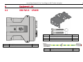
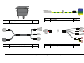
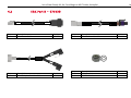
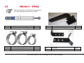
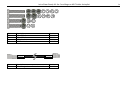
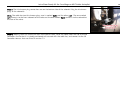
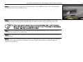
Leica Steer Ready Kit
Installation Manual
Tractor Model:
Case Magnum MX Trimble Autopilot™
Auto-steer Retrofitted
Version 1.2.0
English
Leica Steer Ready Kit for Case Magnum MX Trimble Autopilot
2
Introduction
Purchase
Congratulations on your purchase of a new Leica Steer Ready Kit.
This manual contains important safety directions as well as instructions for installing the product and operating it.
Refer to the Safety Directions for further information. Read carefully through the Installation Manual before you begin
operation of machinery.
The Leica Steer Ready Kit is to be used solely in combination with Leica mojoRTK system. Therefore it’s mandatory to
also observe the directions and instructions contained in the Leica mojoRTK User Manual.
To ensure safety when using the system, please also observe the directions and instructions contained in the User
Manual and Safety Handbook issued by the:
• Agricultural machinery manufacturer.
This manual describes how to install the Leica Steer Ready Kit. Even if you have installed other Leica Geosystems
products before, we recommend you read this manual to ensure correct installation of this product.
Product Identification
The model and serial number of the Leica Steer Ready Kit are indicated on the packaging. Please enter them here, and
always refer to this information when you need to contact your agency or Leica Geosystems authorized service
workshop.
Make:
______________________
Model:
______________________
Serial No.:
______________________
Symbols
Symbols used in this manual have the following meanings:
Type
Description
Indicates an imminently hazardous situation which, if not avoided, will result in death or
serious injury.
Indicates a potentially hazardous situation or an unintended use which, if not avoided,
could result in death or serious injury.
Indicates a potentially hazardous situation or an unintended use which, if not avoided,
may result in minor or moderate injury and / or appreciable material, financial and
environmental damage.
Important paragraphs which must be adhered to in practice as they enable the product
to be used in a technically correct and efficient manner.
Note - The absence of specific alerts does not mean that there are no safety risks involved.
Leica Steer Ready Kit for Case Magnum MX Trimble Autopilot
3
Leica Steer Ready Kit for Case Magnum MX Trimble Autopilot
4
Table of Contents
1
PRODUCT OVERVIEW ................................................................................................................... 6
2
PRE-INSTALLATION VEHICLE PREPARATION .................................................................................... 7
3
SYSTEM DESCRIPTION.................................................................................................................. 7
4
EQUIPMENT LIST ......................................................................................................................... 8
4.1 SRK PART A – 676035 ............................................................................................................................ 8
4.2 SRK PART B – 676038 ...........................................................................................................................10
4.3 SRK PART C – 676022 ...........................................................................................................................11
5
CONTROLLER INSTALLATION ...................................................................................................... 13
5.1 SR CONTROLLER BRACKET MOUNTING ...........................................................................................................13
6
INSTALLING THE STEERING SENSOR ............................................................................................ 15
6.1 MOUNTING THE STEERING SENSOR ................................................................................................................15
7
7.1
7.2
7.3
7.4
7.5
7.6
7.7
7.8
7.9
ROUTING THE WIRING ............................................................................................................... 18
CONNECTING TO THE SR CONTROLLER ............................................................................................................18
ROUTING THE HYDRAULIC VALVE CABLE ..........................................................................................................19
ROUTING THE IN-CAB HARNESS ....................................................................................................................21
ROUTING THE WHEEL ANGLE SENSOR HARNESS ................................................................................................23
INSTALLING THE ENGAGE SWITCH ..................................................................................................................24
ROUTING THE OVERRIDE HARNESS ................................................................................................................25
ROUTING THE POWER CABLE........................................................................................................................26
WIRING CHECK ........................................................................................................................................26
SECURE CABLE HARNESSES .........................................................................................................................26
8
WIRING HARNESS DIAGRAM ....................................................................................................... 27
9
SAFETY DIRECTIONS .................................................................................................................. 28
9.1
9.2
9.3
9.4
9.5
GENERAL ...............................................................................................................................................28
INTENDED USE.........................................................................................................................................28
LIMITS OF USE .........................................................................................................................................29
RESPONSIBILITIES .....................................................................................................................................29
HAZARDS OF USE .....................................................................................................................................30
Leica Steer Ready Kit for Case Magnum MX Trimble Autopilot
5
Leica Steer Ready Kit for Case Magnum MX Trimble Autopilot
6
1
Product Overview
Benefits
The Leica Steer Ready Kit is the first step in getting your equipment Leica mojoRTK ready.
It consists of a Steer Ready Controller & associated Wiring Harness, brackets and bolts which will form the foundation
of your new auto-steer solution.
The Leica Steer Ready Kit is designed to be used in conjunction with the Leica mojoRTK console. The installation of a
Leica mojoRTK console is not included in this manual. Please refer to your local dealer or the relevant manual for further
details on this product.
The Leica Steer Ready Kit is suitable for all Case Magnum MX tractors which have been retrofitted with Trimble Autopilot
valves. Certain vehicle variations and non-standard modifications may affect some cable lengths. Extension cables may
be required, see your local Leica Dealer.
This installation manual will provide the necessary steps to successfully install the Leica Steer Ready Kit.
To understand the user
manual
Use only original parts
To ease the use of this manual please observe the following advice:
Relating to all pictures and schematics, they are to be seen as reference only. There may be slight deviations from the
actual looks of the Leica Steer Ready Kit. These deviations are caused by individual applications and have no impact on
the function capabilities of the Leica Steer Ready Kit.
Leica Geosystems original spare parts are especially designed for the Leica Steer Ready Kit. They live up to the high
design standards for safety and reliability. We advise you, that components or parts, not provided by Leica Geosystems
for the Leica Steer Ready Kit should not be used because they might jeopardize the safety and function of the Leica
Steer Ready Kit. We therefore can not be responsible for such redesign or adaptations. Any obstinate changes on our
Leica Steer Ready Kit void the company warranty. In addition conformity declaration or local authority regulations could
be voided. This also applies to the removal of factory applied seals.
The Leica Steer Ready Kit supports you and improves your efficiency, while working in the field. The responsibility for
quality and work related results rests as always with the driver. As common with most all machinery the basic rule
applies. The more exact the system is adjusted, calibrated and operated the higher the quality of results will be.
2
Pre-Installation Vehicle Preparation
1. Park the vehicle on a hard, level surface and block the front and rear wheels.
2. Align the steering wheels straight ahead.
3. Remove all dirt and trash from the areas of the vehicle where the Leica Steer Ready Kit will be installed.
4. Lower the 3 point hitch to its lowest point. Consult the Tractor’s Operator’s Manual for assistance.
Note: The left and right hand sides of the vehicle are referenced while standing behind the vehicle, facing the normal
direction of travel.
3
General
System Description
The Leica Steer Ready Kit is capable of interfacing to existing actuators and sensors to steer vehicles like tractors and
other self propelled machines in agriculture and forestry applications.
The Leica Steer Ready Kit is composed of the Steer Ready Controller and associated cabling. The Leica Steer Ready Kit
is designed to interface to the Leica mojoRTK system via CAN bus.
The Leica Steer Ready Kit is designed to assist the machine operator to use the equipment more efficiently.
Even when relying on the function of the Leica Steer Ready Kit the driver is still responsible for observation of the
machine and the surrounding area. He should shut down or assume manual steering control in dangerous situations. To
shut down the Leica Steer Ready Kit turn off the power switch so that the light is off.
Leica Steer Ready Kit for Case Magnum MX Trimble Autopilot
7
Leica Steer Ready Kit for Case Magnum MX Trimble Autopilot
4
Equipment List
4.1
SRK Part A – 676035
Qty
1
2
2
Qty
1
Description
Steer Ready Controller
Description
Universal Bracket
M6 x 60mm Bolt
M6 Star Washer
8
Part #
676173
Part #
676171
Qty
1
Description
CAN Extension Cable
Part #
676030
Qty
1
Description
Engage Switch
Part #
676191
Qty
1
Description
mojoRTK SRK ISO-C Cable
Part #
676591
STEERING
OVER RIDE
Cab Interior
676172
TO CAB
EXTERIOR
CAN BUS
# 676186
POWER IN
Wheel Angle
Sensor
ENGAGE &
POWER
SWITCH
Hydraulic
Valve
676172
Qty
1
Description
Wiring Harness – SR Controller
Part #
676172
Qty
1
Description
In-Cab Wiring Harness
Leica Steer Ready Kit for Case Magnum MX Trimble Autopilot
Part #
676186
9
Leica Steer Ready Kit for Case Magnum MX Trimble Autopilot
4.2
SRK Part B – 676038
676178
Power Cable
Qty
1
10
676178
Power Cable
676033
Override Cable
Description
Case Power Cable
676033
Override Cable
Part #
676178
Qty
1
Description
Trimble Override cable
Part #
676033
Qty
1
1
Description
M8 Nyloc Nut
M8 Flat Washer
Part #
Part #
676181
181
676 F T
LE
676181
Hydraulic Cable
676
RIG 181
HT
Qty
1
Description
Trimble Hydraulic Valve Cable
4.3
SRK Part C – 676022
SRK Open kits do not include these components.
For more information consult your dealer.
Qty
1
Description
Linear Sensor 250mm
Part #
676001
Qty
1
1
Description
Worm Drive Clamp 32-50mm
Worm Drive Clamp 70-90mm
Part #
676003
676002
Qty
1
Qty
1
Description
Linear Sensor Mounting Bracket
Description
Linear Sensor Shaft End Brackets
Leica Steer Ready Kit for Case Magnum MX Trimble Autopilot
Part #
676004
Part #
676008
11
Leica Steer Ready Kit for Case Magnum MX Trimble Autopilot
Qty
2
2
8
12
Description
M5 x 45 Bolt
M5 x 25 Bolt
M5 Nyloc Nut
M5 Flat Washer
676175
4pin Extension
Qty
2
Description
Wheel Angle Sensor Extension Cable
Part #
676005
676009
676006
676007
676175
4pin Extension
Part #
676175
12
5
Controller Installation
Before commencing the Installation, lower the 3 point linkage of the tractor to its lowest point and turn the front
wheels of the tractor so that they are positioned straight ahead. Consult the Tractor’s Operator’s Manual for
assistance.
Before beginning this section of the installation, please ensure that the vehicle is turned off and a
DO NOT START tag is attached to the ignition.
The following will give a general outline of the steps necessary to install the SRK Controller assembly.
5.1
SR Controller Bracket Mounting
Step 1: Working from the rear of the vehicle, remove the rear panel by undoing the bolts on either side
of the cab as shown and lifting.
Leica Steer Ready Kit for Case Magnum MX Trimble Autopilot
13
Leica Steer Ready Kit for Case Magnum MX Trimble Autopilot
Step 2: To locate the mounting position shown right and lift the rubber flap. The SR Controller Bracket
slotted bolt hole will align with an existing bolt located on the edge, under the rear window of the Cab
towards the middle.
Step 3: Once located, mount the SR Controller Bracket to the vehicle. Use the M8 nut and washer to
attach it to the mounting bolt.
Step 4: Mount the Steer Ready Controller to the bracket using the M6 bolts and washers as supplied.
14
6
Installing the Steering Sensor
6.1
Mounting the Steering Sensor
Before beginning this section of the installation, please ensure that the vehicle is turned off and a
DO NOT START tag is attached to the ignition.
The tractor needs to be started and stopped during the mounting of the steering sensor. Ensure
that any covers or other items that have been removed to this point in the installation are in a safe
position and that the tractor is in a generally safe condition before it is started.
Step 1: Refer to Section 4.3 of the equipment list to ensure that you have the correct parts.
Step 2: Using the 45mm M5 bolt, attach the cable end of the linear sensor (676001) to the linear
sensor mounting bracket (676004).
Step 3: Join the two parts of the shaft end bracket 676008 using the two M5 x 25mm bolts, two Nyloc
nuts and four washers as shown.
Leica Steer Ready Kit for Case Magnum MX Trimble Autopilot
15
Leica Steer Ready Kit for Case Magnum MX Trimble Autopilot
Step 4: Attach the non-sensor end of the linear sensor to the shaft end bracket assembly using the
45mm M5 bolts as shown.
Step 5: Start the tractor and turn the steering wheel hard lock to the right. Stop the tractor.
Step 6: Using the smaller worm drive clamp mount the shaft end bracket of the linear sensor assembly
to the most left point of the left side steering ram as shown.
16
Step 7: Using the two larger worm drive clamps mount the other end of the linear sensor assembly to
the cylinder of the steering ram as shown. The sensor should be mounted just under full extension at
full lock.
Step 8: Start the tractor again and slowly turn the wheels from lock to lock. Check that there are no
obstructions and the steering ram can not force the sensor past its mechanical stops.
Leica Steer Ready Kit for Case Magnum MX Trimble Autopilot
17
Leica Steer Ready Kit for Case Magnum MX Trimble Autopilot
7
Routing the Wiring
7.1
Connecting to the SR Controller
Before beginning this section of the installation, please ensure that the vehicle is turned off and a
DO NOT START tag is attached to the ignition.
It is essential that the cables are routed throughout the vehicle in a position that is away from
excessive vibration & heat sources such as exhaust manifolds and / or radiators. Also ensure that
there is enough length in the cable to prevent stretching or excessive tension whilst the vehicle is in
normal operation, making sure that it can be mounted securely.
Step 1: Refer to Section 4.1 of the equipment list to ensure that you have the correct Wiring Harness
(Part No. 676172).
Step 2: Locate the Steer Ready Controller that was mounted to the vehicle in Section 5 of this manual.
Step 3: Connect the black Deutsch connector of the Wiring Harness to the black rimmed socket of the
Steer Ready Controller.
18
Step 4: Connect the grey Deutsch connector of the Wiring Harness to the grey rimmed socket of the
Steer Ready Controller.
Step 5: Leave the other end of the SR Controller wiring freely available, as each of these available
connectors will be used for the various components of the Leica Steer Ready Kit.
7.2
Routing the Hydraulic Valve Cable
Step 1: Refer to Section 4.2 of the equipment list to ensure that you have the correct Wiring Harness
(Part No. 676181).
Step 2: Working from the LHS of the vehicle, the Hydraulic Steering Control Valves of the vehicle are
located on the side of the chassis just in front of the Cab. Unscrew the bolts to remove the cover.
Leica Steer Ready Kit for Case Magnum MX Trimble Autopilot
19
Leica Steer Ready Kit for Case Magnum MX Trimble Autopilot
Step 3: The Hirschmann plug connections are on the bottom side of the solenoid. Plug the Hirschman
plugs to the solenoids.
Note: The cable has two Hirschmann plugs, one is marked Right and the other Left. The one marked
Left connects to the front solenoid of the valve and the one marked Right connects to the solenoid at
the rear of the valve.
Step 4: Working from this connection with the hydraulic valve, route the cable under the Cab to the SR
Controller. Ensure that it is suitably positioned and secured with the cable ties, and connect to the SR
Controller Harness that was fitted in section 7.1.
20
7.3
Routing the In-Cab Harness
Inside the vehicle cab there are essentially four connections to be made with the In-Cab Wiring Harness. They are the connection to the Leica
mojoRTK console, the auto engage switch, the manual override cable and the power supply cable.
Step 1: Refer to Section 4.1 of the equipment list to ensure that you have the correct In-Cab Wiring
Harness (Part No. 676186).
Step 2: Locate the entry point into the vehicle’s cab at the rear right side of the cab. This will provide
entry into the cab space near the implement controls.
Step 3: Make a small hole in the rubber and feed the end of the long cable of this harness through the
hole from inside the cab.
Step 4: Locate the Steer Ready Controller Harness that was fitted in Section 7.1 and connect to the
cable of the In-Cab harness that was fed through the hole. Any excess cable can be rolled into a gentle
loop and secured using cable ties.
Leica Steer Ready Kit for Case Magnum MX Trimble Autopilot
21
Leica Steer Ready Kit for Case Magnum MX Trimble Autopilot
Step 5: Locate the mounting position of the associated Leica mojoRTK console, which will typically be
the vehicle’s factory fitted radio DIN slot.
Step 6: Remove the Leica mojoRTK console from the DIN slot using the tools supplied in the Leica
mojoRTK console kit and plug the CAN cable (Part# 675591) into ISO-C plug in the rear of the unit.
If the Leica mojoRTK console has not yet been installed, refer to the Installation
Manual for this product and prepare to install it now. If this product is not available
for install, Skip Step 6 and return to it later.
Step 7: Connect the other end of the CAN cable to the CAN extension cable (Part# 676030). Connect
the extension cable to the In-Cab harness.
Step 8: The CAN cable and its extension can be fed behind the panel, then to the rear right behind the
cab roof lining.
Step 9: Remove the cab pillar panel and conceal the cable behind this panel. Ensure that all connectors
are easily accessible for further installation. Any excess cable can be rolled into a gentle loop and
secured using cable ties.
22
7.4
Routing the Wheel Angle Sensor Harness
This Section is not applicable to SRK Open kits. If installing an SRK open system proceed
to Section 7.5.
Step 1: Refer to Section 4.1 of the equipment list to ensure that you have the correct Wiring Harness
(Part No. 676175).
Step 2: From the Linear Sensor mounted in Section Error! Reference source not found. connect the
Wheel Angle Sensor extension cable to the linear Sensor cable.
Step 3: Route the extension cable under the cab to the SR controller cable installed in Section 7.1,
connect to this cable. If the cable is too short use both extension cables to reach.
Leica Steer Ready Kit for Case Magnum MX Trimble Autopilot
23
Leica Steer Ready Kit for Case Magnum MX Trimble Autopilot
7.5
Installing the Engage Switch
Step 1: Refer to Section 4.1 of the equipment list to ensure that you have the auto-steer engage switch
(Part #- 676191).
Step 2: The auto-engage switch is to be installed in the panel on the right armrest. There should be a
spare place for a switch with a blank insert in the hole. The blank can be removed by lifting it with a
small flat blade screw driver.
Step 3: Feed the cable for the auto-steer engage switch up from under the console to the position that
the switch will finally be placed.
Step 4: Connect the switch to the cable crimps as indicated in the diagrams to the right. Numbers are
labeled on the crimps as well as the switch to assist in this step.
Step 5: Press the switch into the console so that the side that locks down when pressed is towards the
back of the machine.
24
7.6
Routing the Override Harness
Step 1: Refer to Section 4.1 of the equipment list to ensure that you have the manual override cable
(Part No. 676033).
Step 2: The sensor to which the manual override cable is to be connected is located in the same area as
the other hydraulic valves associated with the auto steer.
Step 3: Feed the manual override cable through the entry point into the vehicle’s cab at the rear right
side of the cab, under the vehicle cab through to the left hand side of the vehicle at the front of the
cab.
Step 4: Plug the manual override cable onto the sensor connector as shown.
Step 5: Plug the other end of the manual override cable into the In-Cab harness.
Leica Steer Ready Kit for Case Magnum MX Trimble Autopilot
25
Leica Steer Ready Kit for Case Magnum MX Trimble Autopilot
7.7
Routing the Power Cable
Step 1: Refer to Section 4.1 of the equipment list to ensure that you have the correct power cable (Part
No. 676178).
Step 2: The vehicle’s auxiliary power connector is located on the right side of the vehicle’s cab below
console. Connect the Power supply to the In-Cab harness and connect it to the power connector.
Note: The power cable needs to be tucked behind the vehicle cab lining.
7.8
Wiring Check
Before switching the controller on, use the diagram in Section 8 to check the wiring of the system. All
connectors should be inserted until they have clicked.
7.9
Secure Cable Harnesses
Once the cabling is correct, use the supplied cable ties to secure the harnesses. Where possible group
the cables to use only one cable tie. Secure the cables to other cable harnesses or vehicle structure
(only when it will not cause the cable to be damaged). If cables are too long, wind them up to an
appropriate length and tie together.
Tuck all cables in the cab away or under the floor lining so they cannot be tripped on or damaged.
26
8
Wiring Harness Diagram
676175
676172
676171
Wheel Angle
Sensor
676001
676181
To Valve
Steer Ready Controller
676033
To Override
Sensor
Exterior to Cab
Interior to Cab
676030
676191
675591
676186
mojoRTK Console
676178
Leica Steer Ready Kit for Case Magnum MX Trimble Autopilot
To Machine
Power
27
Leica Steer Ready Kit for Case Magnum MX Trimble Autopilot
9
Safety Directions
9.1
General
28
The Leica Steer Ready Kit is to be used solely in combination with Leica mojoRTK system. Therefore it’s mandatory to
also observe the directions and instructions contained in the Leica mojoRTK User Manual.
Description
The following directions should enable the person responsible for the product, and the person who actually uses the
equipment, to anticipate and avoid operational hazards.
The person responsible for the product must ensure that all users understand these directions and adhere to them.
9.2
Intended Use
Permitted Use
•
•
The Leica Steer Ready Kit is exclusively developed for usage in agriculture or forestry by persons in control.
The Leica Steer Ready Kit is only intended to be fitted to agricultural tractors. It is not permitted to install this
product in any other vehicles.
Adverse Use
•
•
•
•
•
Use of the product without instruction.
Use outside of the intended limits.
Disabling safety systems.
Removal of hazard notices.
Opening the product using tools, for example screwdriver, unless this is specifically permitted for certain
functions.
Modification or conversion of the product.
Use after misappropriation.
Use of products with obviously recognizable damages or defects.
Use with accessories from other manufacturers without the prior explicit approval of Leica Geosystems.
Inadequate safeguards at the work site, for example when using on the intended site.
The Leica Steer Ready Kit is not suitable for applications on narrow dikes or on steep hillsides, where danger of
vehicle roll over exists.
•
•
•
•
•
•
Adverse use can lead to injury, malfunction and damage. It is the task of the person responsible for the equipment to
inform the user about hazards and how to counteract them.
The product is not to be operated until the user has been instructed on how to work with it.
Unauthorized modification of agricultural machine by mounting or installing the product may alter the function and
safety of the machine.
Precautions:
Follow the instructions of the machine manufacturer. If no appropriate instruction is available, ask machine
manufacturer for instructions before mounting or installing the product.
9.3
Limits of Use
Environment
Suitable for use in an atmosphere appropriate for permanent human habitation: not suitable for use in aggressive or
explosive environments.
Local safety authorities and safety experts must be contacted before working in hazardous areas, or in close proximity
to electrical installations or similar situations by the person in charge of the product.
9.4
Responsibilities
Manufacturer of the
product
Leica Geosystems AG, CH-9435 Heerbrugg, hereinafter referred to as Leica Geosystems, is responsible for supplying the
product, including the user manual and original accessories, in a completely safe condition.
Manufacturers of non
Leica Geosystems
accessories
The manufacturers of non Leica Geosystems accessories for the product are responsible for developing, implementing
and communicating safety concepts for their products, and are also responsible for the effectiveness of those safety
concepts in combination with the Leica Geosystems product.
Leica Steer Ready Kit for Case Magnum MX Trimble Autopilot
29
Leica Steer Ready Kit for Case Magnum MX Trimble Autopilot
Person in charge of the
product
•
•
•
•
30
The person in charge of the product has the following duties:
To understand the safety instructions of the product.
To be familiar with local regulations relating to safety and accident prevention.
To inform Leica Geosystems immediately if the product and the application becomes unsafe.
The person responsible for the product must ensure that it is used in accordance with the instructions. This person is
also accountable for the training and the deployment of personnel who use the product and for the safety of the
equipment in use.
Unauthorized modification of machines by mounting the product may alter the function and safety of the machine.
Precautions:
Follow the instructions of the machine manufacturer. If no appropriate instruction is available, ask machine
manufacturer for instructions before mounting the product.
9.5
Hazards of Use
Only Leica Geosystems authorized service workshops are entitled to repair these products.
Beware of inadequate steering if machine is defective like after a crash or other damaging events or alterations to the
machine.
Precautions:
Periodically perform control measurements and field adjustments on the machine as specified in the User Manual.
While steering or navigating the machine accidents may occur due to a) the operator not paying attention to the
surroundings (persons, ditches, traffic, etc.), or b) malfunctions (…of a system component, interference, etc).
Precautions:
The operator assures that the machine is operated, guided and monitored by a qualified user (e.g. driver). The user has
to be able to take emergency measures, for example an emergency stop.
The absence of instruction, or the inadequate imparting of instruction, can lead to incorrect or adverse use, and can
give rise to accidents with far-reaching human, material, financial and environmental consequences.
Precautions:
All users must follow the safety directions given by the manufacturer and the directions of the person responsible for
the product.
During dynamic applications, there is a danger of accidents occurring if the user does not pay attention to the
environmental conditions around, for example obstacles, excavations or traffic.
Precautions:
The person responsible for the product must make all users fully aware of the existing dangers.
Inadequate securing of the work site can lead to dangerous situations, for example in traffic, on building sites, and at
industrial installations.
Precautions:
Always ensure that the work site is adequately secured. Adhere to the regulations governing safety and accident
prevention and road traffic.
If the product is improperly disposed of, the following can happen:
If polymer parts are burnt, poisonous gas are produced which may impair health.
By disposing of the product irresponsibly you may enable unauthorized persons to use it in contravention of the
regulations, exposing themselves and third parties to the risk of severe injury and rendering the environment liable to
contamination.
Precautions:
The product must not be disposed with household waste. Dispose of the product appropriately in accordance with the
national regulations in force in your country. Always prevent access to the product by unauthorized personnel.
Product specific treatment and waste management information can be downloaded from the Leica Geosystems home
page at http://www.leica-geosystems.com/treatment or received from your Leica Geosystems dealer.
On public roads and drives always disengage the Leica Steer Ready Kit via the power switch. For safety reasons it is
better if you keep one hand on the steering wheel, when using the Leica Steer Ready Kit at speeds over 6 mph (10
km/h). In case of malfunction you are able to take action immediately.
Leica Steer Ready Kit for Case Magnum MX Trimble Autopilot
31
Leica Steer Ready Kit for Case Magnum MX Trimble Autopilot
32
With exemption of the driver no other person should ride in the drivers area of the vehicle fitted with a Leica Steer
Ready Kit. Additional persons could distract or block visibility of the driver from operating and observing the Leica Steer
Ready Kit which could lead to dangerous situations.
The presence of a rider on a passenger seat is only acceptable for brief observations or for training purpose. The
passenger seat is never considered a children seat. Only persons especially experienced, with the operation of the
machine, should be considered for schooling on a machine which is fitted with a Leica Steer Ready Kit.
Pay special attention that no children are near or on the vehicle which is fitted with a Leica Steer Ready Kit, especially
when the Leica Steer Ready Kit is active. Children are unpredictable and supervision is limited when operating the Leica
Steer Ready Kit. They might be exposed to additional danger.
Before starting field work make yourself comfortable with the use of the Leica Steer Ready Kit and the vehicle. As soon
as the Leica Steer Ready Kit is activated, an adult, responsible person has to be in charge of supervision and monitoring.
In dangerous situations it is always safer to disengage the Leica Steer Ready Kit and drive by hand, in order to avoid
personal injury or material damage.
Danger Zone
At no time should there be any person within the danger zone after the Leica Steer Ready Kit is activated.
At any sign of danger the operator should deactivate the Leica Steer Ready Kit immediately. He has to ask any person
within the danger zone to leave promptly. Only when there are no more people within the danger zone can he reactivate the Leica Steer Ready Kit.
For service and control duties only authorized persons can enter the danger zone, after verbal confirmation with the
operator. Such people have to be clearly informed about possible dangers before entering the danger zone. All activities
between the operator and these persons should be discussed before hand. All service, adjustment and control duties on
this Leica Steer Ready Kit should only take place if technically possible, on a parked vehicle with the engine turned off.
People present within the danger zone are exposed to serious bodily harm or even death. People could be run over in
case of malfunction of the machine. The operator is obligated to stop the vehicle as soon as people enter the danger
zone.
Prepare for possible
emergencies
•
•
Always have a fire extinguisher and First Aid kit at hand.
Always have actual emergency phone numbers for Fire department, ambulance and doctor handy.
Leica Steer Ready Kit for Case Magnum MX Trimble Autopilot
33
Leica Steer Ready Kit for Case Magnum MX Trimble Autopilot
34
Purchase Returns
Leica Geosystems offers customers the ability to return any agricultural products purchased within Australia under our
exclusive 8n8 Satisfaction Guarantee Program. You will receive a full refund of your purchase price if you meet the
following criteria:
The equipment must be returned and received in the Leica Geosystems Brisbane Qld office within
8 days of the invoice date.
The equipment must have no more than 8 hours of auto-steer operating time on the system meter.
The equipment must be in ‘as new’ condition and in original packaging.
If you are not satisfied for any reason, you may return your new mojoRTK products... no questions asked. This is the
Leica 8n8 Satisfaction Guarantee.
Warranty
Leica Geosystems offers its Standard International Warranty which is 12 months for all agricultural product purchases,
and 90 days for battery products. Please go to the website to review the warranty document.
Leica Steer Ready Kit for Case Magnum MX Trimble Autopilot
35
Leica Geosystems Pty Ltd
270 Gladstone Road
Dutton Park QLD 4102
Australia
Phone: +61 7 3891 9772
www.mojoRTK.com
Original text
Printed in Singapore © 2009 Leica Geosystems Pty Ltd, Brisbane, Australia
676107 (Version 1.2.0en)