1
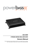
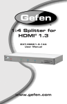
®
EXT-DVI-148
User Manual
www.gefen.com
ASKING FOR ASSISTANCE
Technical Support:
Telephone
Fax
(818) 772-9100
(800) 545-6900
(818) 772-9120
Technical Support Hours:
8:00 AM to 5:00 PM Monday through Friday, Pacific Time
Write To:
Gefen, LLC
c/o Customer Service
20600 Nordhoff St
Chatsworth, CA 91311
www.gefen.com
[email protected]
Notice
Gefen, LLC reserves the right to make changes in the hardware, packaging and
any accompanying documentation without prior written notice.
1:8 DVI Distribution Amplifier is a trademark of Gefen, LLC
© 2010 Gefen, LLC. All rights reserved.
All trademarks are the property of their respective owners.
Rev A2
CONTENTS
1
Introduction
2
Operation Notes
3
Features
4
Panel Layout
5
Panel Descriptions
6
Connecting the 1:8 DVI Distribution Amplifier
6
Wiring Diagram
7
EDID Management
8
EDID Modes
10 Specifications
11 Warranty
INTRODUCTION
Congratulations on your purchase of the 1:8 DVI Distribution Amplifier. Your
complete satisfaction is very important to us.
Gefen
Gefen delivers innovative, progressive computer and electronics add-on solutions
that harness integration, extension, distribution and conversion technologies.
Gefen’s reliable, plug-and-play products supplement cross-platform computer
systems, professional audio/video environments and HDTV systems of all sizes
with hard-working solutions that are easy to implement and simple to operate.
The Gefen Extender for HDMI 1.3 Over One Fiber with IR
The 1:8 DVI Distribution Amplifier is the perfect solution for anyone who needs
to send one source of digital high definition video to multiple displays at the
same time. It supports all DVI equipment, such as computers, HD-DVD players
and satellite set top boxes and all DVI displays. DVI (Digital Visual Interface)
is a common connector used throughout the industry to connect digital video
displays to video sources. In operation, the digital video source is connected to
the distribution amplifier on one side. On the other side, eight video outputs are
available to be used in part or in full. Once the unit is connected and powered,
your video source is routed to up to eight digital displays at the same time.
For home theater applications, the unit is HDCP (high bandwidth digital content
protection) compliant, making it effective for use with all HDTV displays. HDCP
is a standard “key” encoded into the DVI signal to prevent video data from being
pirated. HDCP was strongly endorsed by the entertainment industry. If a source
device is HDCP coded and is connected to a HDTV display or projector via DVI
without the proper HDCP decoding mechanism, the picture is relegated to “snow”
or in some cases, a very low (480p) resolution. In order to see protected content,
the source, the display and any device in between must be equipped with DVI
connections that can enable HDCP using “software key” decoding.
How It Works
Simply connect your DVI video source to the 1:8 DVI Distribution Amplifier input
using the supplied DVI cable. Then connect up to eight DVI displays to the unit’s
eight DVI outputs. Once connected and powered, your video source will be seen
on all eight displays at the same time.
1
OPERATION NOTES
READ THESE NOTES BEFORE INSTALLING OR
OPERATING THE 1:8 DVI DISTRIBUTION AMPLIFIER
•
When using the 1:8 DVI Distribution Amplifier, it is important to use devices/
displays that have similar or compatible resolutions/features. This will ensure
that the single video/audio signal produced by the source device is accepted
by all of the connected output devices/displays. See page 7 for more
information.
2
FEATURES
Features
•
Distributes easily up to eight DVI/HDMI displays
•
Maintains 480i, 480p, 720p, 720i, and 1080i, 1080p resolutions
•
Maintains highest DVI single link video resolution
•
Maintains highest DVI digital audio signal
•
Supports HDCP compliant devices
•
DVI or DVI to HDMI cables are used to connect the inputs and switcher
output
•
Installs in seconds
Package Includes
(1) 1:8 DVI Distribution Amplifier
(1) 6 ft. DVI cable (M-M)
(1) 24VDC Power Supply
(1) Rack Ears
(1) Quick Start Guide
3
1
3
Back
Front
4
2
PANEL LAYOUT
4
PANEL DESCRIPTIONS
1
DVI Out (1 - 8)
Connect a DVI display to each of these DVI ports.
2
Power
This LED indicator will glow bright red when the included power supply is
connected to the 1:8 DVI Distribution Amplifierr and the AC power cord is
connected to an available electrical outlet.
3
DVI In
Connect the computer (or other DVI source) to this DVI port.
4
24 VDC
Connect the included 24V DC power supply to this power receptacle and
connect the AC power cord to an available electrical outlet.
5
CONNECTING THE 1:8 DVI DISTRIBUTION AMPLIFIER
How to Connect the 1:8 DVI Distribution Amplifer
1.
Connect a computer (or other DVI source) to the DVI input on the back panel
of the 1:8 DVI Distribution Amplifierr using the included DVI cable.
2.
Connect up to eight DVI displays to the DVI outputs on the front panel of the
1:8 DVI Distribution Amplifier.
3.
Connect the included 24V DC power supply to the power receptacle on the
back panel of the 1:8 DVI Distribution Amplifier. Connect the opposite end of
the AC power cord into an available electrical outlet.
Wiring Diagram for the 1:8 DVI Distribution Amplifier
DVI CABLE
Computer
p
Splitter
Monitor
Monitor
Monito
Monitor
Monitor
Monitor
Monitor
Monitor
Monitor
6
EXT-DVI-148
EDID MANAGEMENT
EDID: What is it and what is it used for?
Under normal circumstances, an source device (digital and analog) will require
information about a connected device/display to assess what resolutions
and features are available. The source can then cater its output to send
only resolutions and features that are compatible with the attached device/
display. This information is called EDID (Extended Display Information Data)
and a source device can only accept and read one EDID from a connected
device/display. Likewise, the source an only output one resolution for use by a
connected device/display.
Why is EDID so important with the 1:8 DVI Distribution Amplifier?
The 1:8 DVI Distribution Amplifierr is complex piece of technology that replicates
and switches between multiple inputs and outputs. Each connected source
device will require one EDID to read. EDID management is carefully handled by
1:8 DVI Distribution Amplifierr to provide a single EDID for each source to read.
What options do I have to manage the EDID in the 1:8 DVI Distribution
Amplifier?
First, it is important to note that each source device can only output one video/
audio signal type. This includes resolutions and timings. When multiple devices/
displays are used, such as with the 1:8 DVI Distribution Amplifier,
r it is important
to use devices/displays that have similar or compatible resolutions/features. This
will ensure that the single video/audio signal produced by the source device is
accepted by all of the connected output devices/displays.
The user has the option, through a combination of DIP switch settings within the
1:8 DVI Distribution Amplifier,
r to choose how the unit will manage the EDID from
multiple HDMI devices/displays. Therefore the user has some control over the
resolutions/features that the source devices will output. The 1:8 DVI Distribution
Amplifierr has a multiple EDID management modes that will control how the EDID
information from multiple devices/displays are combined, ignored, and routed.
How do I change EDID modes in the 1:8 DVI Distribution Amplifier?
There is an bank of 8 DIP switches located on the main-baord inside of the
1:8 DVI Distribution Amplifier. DIP switches 1, 2, and 5 are used in different
combinations to manage the EDID modes.
To access these DIP switches it will be required to open the unit. To do this,
remove all screws on the underside and side of the unit. Remove all HEX screws
on the rear panel. This includes the screws above each DVI port. Carefully slide
the unit apart.
7
EDID MANAGEMENT
EDID Modes
The diagrams below illustrate the DIP switch bank for each EDID mode. Use DIP
switches 1, 2, and 5 to select the desired EDID management mode.
EDID Mode 0
1
•
2
3
4
5
6
7
8
EDID is copied from the first DVI output.
EDID Mode 1
1
•
2
3
4
5
6
7
8
Same as EDID Mode 0 and adds basic audio support.
EDID Mode 2
1
•
2
3
4
5
6
7
8
Same as EDID Mode 0 and adds full audio support.
EDID Mode 3
1
•
2
3
4
5
6
7
8
EDID is generated based on the common video features of all the connected
devices.
8
EDID MANAGEMENT
EDID Mode 4
1
•
2
3
4
5
6
7
8
Same as EDID Mode 3 and adds basic audio support.
EDID Mode 5
1
•
2
3
4
5
6
7
8
Same as EDID Mode 3 and adds full audio support.
EDID Mode 6
1
•
2
3
4
5
6
7
8
EDID is generated based on the common video features of all the connected
devices.
EDID Mode 7 (Default Setting)
1
•
2
3
4
5
6
7
8
EDID is passed unmodified from the device connected to the first active DVI
output port.
9
SPECIFICATIONS
Maximum Pixel Clock................................................................................165 MHz
Input Video Signal................................................................................1.2 volts p-p
Input DDC Signal...........................................................................5 volts p-p (TTL)
Input Video Connector.....................................(1) DVI, 29-pin, female (digital only)
Output Video Connector..................................(8) DVI, 29-pin, female (digital only)
Power Consumption .............................................................................60W (max.)
Power Supply .............................................................................................24V DC
Dimensions (W x H x D) ....................17” x 1.6” x 5.4” (432mm x 41mm x 137mm)
Shipping Weight ................................................................................6 lbs. (2.7 kg)
Rack Mountable............................................................................... 1U rack space
10
WARRANTY
Gefen warrants the equipment it manufactures to be free from defects in material
and workmanship.
If equipment fails because of such defects and Gefen is notified within two (2)
years from the date of shipment, Gefen will, at its option, repair or replace the
equipment, provided that the equipment has not been subjected to mechanical,
electrical, or other abuse or modifications. Equipment that fails under conditions
other than those covered will be repaired at the current price of parts and labor in
effect at the time of repair. Such repairs are warranted for ninety (90) days from
the day of reshipment to the Buyer.
This warranty is in lieu of all other warranties expressed or implied, including
without limitation, any implied warranty or merchantability or fitness for any
particular purpose, all of which are expressly disclaimed.
1.
Proof of sale may be required in order to claim warranty.
2.
Customers outside the US are responsible for shipping charges to and from
Gefen.
3.
Copper cables are limited to a 30 day warranty and cables must be in their
original condition.
The information in this manual has been carefully checked and is believed to
be accurate. However, Gefen assumes no responsibility for any inaccuracies
that may be contained in this manual. In no event will Gefen be liable for
direct, indirect, special, incidental, or consequential damages resulting from
any defect or omission in this manual, even if advised of the possibility of such
damages. The technical information contained herein regarding the features and
specifications is subject to change without notice.
For the latest warranty coverage information, refer to the Warranty and Return
Policy under the Support section of the Gefen Web site at www.gefen.com.
PRODUCT REGISTRATION
Please register your product online by visiting the Register Product page
under the Support section of the Gefen Web site.
11
Rev A2
20600 Nordhoff St., Chatsworth CA 91311
1-800-545-6900
818-772-9100
www.gefen.com
Pb
This product uses UL listed power supplies.
fax: 818-772-9120
[email protected]