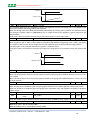
1
ul. Konstantynowska 79/81 95-200 Pabianice, Poland phone/fax 42 2152383,2270971 e-mail: [email protected] Frequency Inverter FA-1L/FA-3H User Manual v. 1.0.0 domestic and industrial automation The notes concerning the relay's operational safety have been indicated with the following symbols. All information and recommendations labeled this way must be observed. Risk of electric Shock Potentially dangerous situation which may give rise to risks for operators or cause damage to the inverter Information concerning the structure, operation and service of the inverter Important information or useful hint. Practical advice or problem solution. Exemplary application or function. Frequency inverter FA-1L…/FA-3H… – User Manual v. 1.0.0 2 domestic and industrial automation Table of Contents Part 1. Inspection before and after unpacking .......................................................................................4 Inverter Specification Label ....................................................................................................................4 Model number convention .....................................................................................................................4 Part 2. Installation ..................................................................................................................................5 Safety Precautions ..................................................................................................................................5 Conditions for Use ..................................................................................................................................6 Installation ..............................................................................................................................................6 Part 3. Wiring ..........................................................................................................................................7 Basic Connection Diagram ......................................................................................................................7 Main Circuit Terminals ............................................................................................................................7 Specification of MCCB, and electric cable...............................................................................................9 Control Circuit Terminals ........................................................................................................................9 Part 4. Operating Keyboard ..................................................................................................................12 Operating keyboard specification and function description ................................................................12 Example for parameters set ..................................................................................................................13 Menu Group ..........................................................................................................................................15 Monitor Function: S00 – S15.................................................................................................................15 Basic function Group:F00-F50...............................................................................................................16 User Function Group:A00-A55 ..............................................................................................................31 IO function group:o00-o68 ...................................................................................................................40 Multi-speed PLC Group:H00-H55..........................................................................................................60 V/F Curve Group:U00-U15 ....................................................................................................................68 PID parameter: P00-P12 .......................................................................................................................68 Speed-loop parameter: C00-C31 ..........................................................................................................71 Motor parameter: b00-b22...................................................................................................................75 System parameter: y00 - y17 ................................................................................................................77 Part 5 – Fault Diagnosis & Solutions .........................................................................................................80 Problems and solutions .........................................................................................................................80 Part 6 – Specification ................................................................................................................................82 Types table ............................................................................................................................................87 Braking Unit ..........................................................................................................................................89 Frequency inverter FA-1L…/FA-3H… – User Manual v. 1.0.0 3 domestic and industrial automation Part 1. Inspection before and after unpacking 1) Before unpacking the product, please check if its package is damaged due to careless transportation, and if the specifications and type of the product complies with the order. 2) Check the nameplate on the side of the frequency inverter to ensure that the product you have received is right the one you ordered. Please contact the supplier of F&F products if any problems are found. Inverter Specification Label (nameplate) Pic. 1) Inverter nameplate Model number convention Pic. 2) Identification of the type of inverter Particular attention should be given to the difference between the onephase inverters 230V and 3-phase 400V. Connection of 3-phase 400V for 1phase inverter can cause serious damage. Frequency inverter FA-1L…/FA-3H… – User Manual v. 1.0.0 4 domestic and industrial automation Part 2. Installation Safety Precautions Never connect the A.C. power supply to the output terminals (U, V, W) of the frequency inverter. Fix and lock the panel before supplying power so as to avoid the danger caused by the poor capacity or other components inside the inverter. After the power supply is switched on, do not perform wiring or check, etc. Don’t touch the circuit boards or its parts or components in the inverter when it is powered, so as to avoid danger of electric shock. If the power supply is switched off, do not touch the PCB or other parts inside the inverter within 5 minutes after the keyboard indicator lamp goes off, and you must check by using the instrument that the inverter has completely discharged all its capacity before you start to work inside the inverter. Otherwise, there will be the danger of electric shock. The static electricity in human body will cause serious damage to the MOS field effect transistor in the inverter. Please keep your hands away from the PCB, IGBT and other internal parts before taking actions to prevent static electricity. Otherwise, faults may be caused. Please don’t shut off the unit by turning off the power supply. Turn off the power supply after the motor has stopped its operation. In use, the earthling terminal ( ) of the frequency inverter must be grounded to the earthling connections correctly and securely according to the national electrical safety specifications and other applicable standards. . Attention: The inverter is designed to operate in the power supply TN-S with an effective reset. Failure to do so may lead to the appearance on the metal casing inverter dangerous potentials which are high risk for both manual and inverter Frequency inverter FA-1L…/FA-3H… – User Manual v. 1.0.0 5 domestic and industrial automation Conditions for Use 1. Ambient temperature -10℃~40℃. 2. Avoid electromagnetic interference and keep the unit away from the interference source. 3. Prevent dropping water, steam, dust, powder, cotton fiber or fine metal powder from entering it. 4. Prevent oil, salt and corrosive gas from entering it. 5. Avoid vibration. 6. Avoid high temperature and moisture and avoid being wetted due to raining, with the humidity below 90%RH (not dewing). 7. Prohibit the use in the dangerous environment where inflammable or combustible or explosive gas, liquid or solid exists. Installation The frequency inverter must be installed by wall hooking in the indoor room with adequate ventilation, with enough space left between it and the adjacent objects or damper (walls) surrounding it, as shown in the below figure: Pic. 3) Example of appropriate building inverter Frequency inverter FA-1L…/FA-3H… – User Manual v. 1.0.0 6 domestic and industrial automation Part 3. Wiring Basic Connection Diagram Pic. 4) Inverter wiring diagram Frequency inverter FA-1L…/FA-3H… – User Manual v. 1.0.0 7 domestic and industrial automation Main Circuit Terminals For wiring of main circuit, please refer to national rule. Don’t connect A.C. input power to the output terminals U, V, W of the frequency inverter. Don’t install power factor capacitance or resistance-capacitance absorbing device between the output terminals U, V, W of the frequency inverter. To disassemble or replace the motor, the input power supply must be turned off for the frequency inverter. Do not drop Metal scrap foam or lint into the frequency inverter, otherwise the machine will be faulted. The motor or power supply can be switched on/off only after the inverter stops its output. When the carrier frequency is less than 3kHz, the distance between the frequency inverter and motor must not be greater than 50 meters (maximum). When it is above 4kHz, this distance should be reduced. The cable for this connection had better be laid in metal conduit. In order to prevent unexpected accidents, earthling terminal E or must be grounded to the earth securely (the grounding resistance should be below 100Ω). The cable size should be greater than half of below- mentioned corresponding cable size; otherwise current leakage will happen possibly It is recommended to use between the inverter and the motor dedicated shielded motor cables. Pic. 5) Terminal block to connect the power circuit Terminal Function R/L1 S/L2 T/L3 B1, B2 DC+2, DCDC+1, DC+2 Description Connected to 3-phase power, (Single input connected to R, T) Power input for frequency inverter Particular attention should be given to the difference between the one-phase inverters 230V and 400V 3-phase. Connection of 3-phase 400V for 1phase inverter can cause serious damage. Connection point for Connect brake resistance braking resistance DC Bus output Connect the brake unit. DC reactance connection Connect DC reactance (No short circuit). terminal. Frequency inverter FA-1L…/FA-3H… – User Manual v. 1.0.0 8 domestic and industrial automation U/T1 V/T2 W/T3 /PE 3 Phase Output Connected to 3-phase motor Earthling terminal E or earth securely. Grounding point must be grounded to the Specification of MCCB, and electric cable Type FA-1L007 FA-1L015 FA-1L022 FA-1L040 FA-3H007 FA-3H015 FA-3H022 FA-3H040 FA-3H055 FA-3H075 FA-3H110 Input Current A 9 17.5 24 36 3.3 5 7A 11A 16.5A 20A 28A Output Current A 4 7 10 16 2.5 3.7 5A 8.5A 13A 16A 25A Motor Capacity kW 0.75kW 1.5kW 2.2kW 4.0kW 0.75kW 1.5kW 2.2kW 4.0kW 5.5kW 7.5kW 11kW MCCB A 16 25 40 63 10 10 16 25 32 40 63 Power Cable mm2 2,5 2,5 4,0 6,0 1,5 1,5 2,5 2,5 4,0 4,0 6,0 Control Circuit Terminals Take special attention to the separation of the control circuit of the power circuit. Random combination of the two circuits may cause electric service and / or damage to the drive. Give attention to the maximum allowable voltage which may be applied to the inputs of the inverter control and maximum load controller outputs. Exceeding these values may damage the drive For external control of frequency inverter, an isolation device should be used for the control lines or screened cable should be used. A screened cable should be used as the signal connection line for input command and must be routed separately as well, and it had better be installed far from the main circuit Frequency inverter FA-1L…/FA-3H… – User Manual v. 1.0.0 9 domestic and industrial automation Pic. 6) The control circuit terminal block Terminal Function DI1 DI1 Input Terminal DI2 D2 Input Terminal Description Input Signal Multi-functions input terminal. DI3 DI3 Input Terminal DI4 DI4 Input Terminal DI5 DI5 Input Terminal DI6 DI6 Input Terminal For details Please read o36~o46 Enter a valid polarity can be controlled by o47 DI1~DI4 Drive model can be controlled by JP4 DI5~DI6 Drive model can be controlled by PLC output terminal DI6 can be set as digital pulse input PLC Control DI5-DI6 Drive model PLC PLC Control Terminal COM Common terminal +10V, GND Analog Power Drain Drive : PLCconnect 24VDC or external lower Source Drive: PLC connect COM The biggest output 24V/200mA. Cannot connect COM with GND in any situation The biggest output +10V/50mA. Cannot connect COM with GND in any situation Frequency inverter FA-1L…/FA-3H… – User Manual v. 1.0.0 10 Analog Output Output Signal domestic and industrial automation AI1 Multifunction Analog Input Signal 1 AI2 Multifunction Analog Input Signal 2 AI3 Multifunction Analog Input Signal 3 SPA/COM Output Signal 1 SPB/COM Output Signal 2 TA1/TB1/TC1 Output Signal 3 DA1 Multifunction Analog Output Signal 1 DA2 Multifunction Analog Output Signal 2 JP5 cut/JP3 1-2: -10V~+10V JP5 cut/JP3 2-3: 0~10V JP5 connect: 0~20mA can be regulated o00/o01 Set the input voltage / current range o06/o07 Set the input signal corresponding to set value JP6 cut: 0~10V JP6 connect: 0~20mA can be regulated o02/o03 can set input voltage/ current arrange o08/o09 set the input signal corresponding to set value JP7 cut: 0~10V JP7 connect: 0~20mA can be regulated o04/o05 can set input voltage/ current arrange o10/o11 set the input signal corresponding to set value Open Collector signal when the output action (24VDC/50mA) Common terminal COM , the output function can set by o21, o22 SPA, SPB provide hi-speed pulse output fun - ction. After setting functions by o61~o64 Frequency inverter will take effect again. Relay Output - max. 250VAC/5A or 24VDC/5A. TA1-TC1 open, TB1-TC1close, the output function can set by o23 JP1 1-2: 0~20mA JP1 2-3: 0~10VDC o15 set analog output analog functions o17/o18 set the output signal arrange JP2 1-2: 0~20mA JP2 2-3: 0~10VDC o16 Set analog output analog functions o19/o20 set the output signal arrange Frequency inverter FA-1L…/FA-3H… – User Manual v. 1.0.0 11 domestic and industrial automation Part 4. Operating Keyboard Operating keyboard specification and function description Pic. 7) An example of the use of the control panel Frequency inverter FA-1L…/FA-3H… – User Manual v. 1.0.0 12 domestic and industrial automation Example for parameters set F01 keyboard set the frequency from 50.00Hz to 25.00Hz. Pic. 8) An example of a parameter edition 1. Under monitoring status, press PRG into parameter group to query status; 2. Through potentiometer Switch to F00-63 Basic FG; 3. Press PRG , or ENTER, enter into F00-63 Basic FG parameter group to query status; 4. Through potentiometer Switch to F01Fre. Set by K; 5. Press PRG 6. Through , or ENTER, enter into F01 Fre. Set by K parameter modify status; PRG , or ENTER, adjust the value is modified bit; 7. Through potentiometerHas been modified to adjust the bit values; 8. Finish the adjustment, press 9. Press ESC SET ;if cancel the change, press ESC to escape to the modify status; to exit to previous menu. Parameter uploads to the keyboard Parameter Item Description y01 parameter upload to N function 0 Frequency inverter FA-1L…/FA-3H… – User Manual v. 1.0.0 13 domestic and industrial automation the keyboard System parameter upload to the memory area1 in the keyboard 1 System parameter upload to the memory area2 in the 2 keyboard System parameter upload to the memory area3 in the keyboard 3 System parameter upload to the memory area4 in the keyboard 4 Clear memory area in the keyboard1, 2, 3, 4 5 1. Example. System parameter upload to the memory area3 in the keyboard 1. Under monitoring status, press PRG into parameter group to check status; 2. Through potentiometerSwitch to y00-23 System FG; 3. Press PRG , or ENTER, enter into y00-23 System FG parameter group to check status; 4. Through potentiometerSwitch to y01P Upload To K; 5. Press PRG , or ENTER, enter into y01P Upload To K parameter modify status; 6. Through potentiometer adjust value to be 3 ; Frequency inverter FA-1L…/FA-3H… – User Manual v. 1.0.0 14 domestic and industrial automation 7. Finish the adjustment, press change, press 8. Press ESC ESC SET ;the speed for upload will display on the LED;if cancel the to escape to the modification status; to exit to previous menu. Parameters Groups Code S F A O H U P C b y Function Description Refer to page Błąd! Nie Monitor Function Monitor frequency, current and other 16 monitor zdefiniowano Group objects zakładki. Frequency setting, control mode, acceleration time Basic Function Group 16 and deceleration time User Function Group Monitor, protection, communication setting 30 Błąd! Nie IO Function Group Analog, digital input, output function zdefiniowano zakładki. Błąd! Nie Multi-speed PLC Multi-speed running, PLC running zdefiniowano Group zakładki. Błąd! Nie V/F parameter Group User defined V/F curve zdefiniowano zakładki. Błąd! Nie PID Function Group Internal PID parameter setting zdefiniowano zakładki. Błąd! Nie Speed ring function Current ring, speed running, PG parameter zdefiniowano Group zakładki. Motor parameter Motor parameter setting 74 Group System Function Parameter reset, fault query, product information, 77 Group parameter protection Monitor Function: S00 – S15 Code S00 S01 S02 S03 S04 S05 Function Setting Frequency Real Frequency Motor real Current Percentage of Motor Current DC Bus Voltage The Output Voltage Unit Fact. Change Limited Current inverter real setting frequency Hz - N Current inverter real output frequency Hz - N Valid value of motor actual current A - N The percentage of actual motor current and rated current % Detection value of DC bus voltage V - N The real output voltage V - N Description Frequency inverter FA-1L…/FA-3H… – User Manual v. 1.0.0 15 domestic and industrial automation Motor Real obr Motor real running speed /min N Speed Under running, the real speed of the motor=60*the real output frequency *Gain Speed surveillance /pole of the motor. Example: the real output frequency 50.00Hz, Gain Speed surveillance A35=100.0%, the pole of the motor b03/b16=2, the real speed of the motor=1500rpm. When stop, based Residual voltage test motor speed, renew speed 500ms. The real speed =60*residual frequency*Gain Speed surveillance / the pole of the motor Max display of motor real speed 9999rpm. Total Running hour/ S07 The total running time for every time N Time day When the output, the frequency inverter calculated the running time. Total running time can be cleared up automatically with A33 selecting reboot or continue accumu lation after reboot Total running time of the units can be changed by parameter A34, you can choose hours or days as the unit IGBT Temperao S08 Test the temperature of IGBT in the frequency C N ture ℃ S09 PID Set Point PID Adjust run-time values of the percentage of a given % N S10 PID Feedback PID Adjust run-time values of the percentage of feed back % N Motor Output S11 The percentage of actual output power of motor % N Frequency The output frequency of the motor=the actual frequency of the motor *A36 the regulate of the motor frequency Max display of the output frequency 2999.9 Excitation Heft S12 Motor’s set excitation heft percentage % N Set Value Excitation Heft S13 Motor’s actual excitation heft percentage % N Actual Value Torque Heft Set S14 Motor set torque percentage % N Value Torque Heft S15 Motor actual torque hefts percentage % N Actual Value S06 Basic function Group:F00-F50 Code F00 Function Control Mode Setting Range V/F control Sensor less vector control 0 1 Unit Fact. Change Limited - 0 N 0. V/F Control It is not sensitive to motor parameters, can be used as power supply; for motor control, using the combination of vector control and V / F control strategies, appropriately adjusts motor parameters, obtain high-performance control effect; suitable for a inverter driving a motor occasions; suitable for a inverter driving multiple motors occasions; suitable for the inverter as a variable frequency power supplies. 1. Sensor less vector control High-performance speed sensor less vector control; need to set the appropriate electrical parameters or the motor parameter tuning; truly achieved the decoupled AC motor, so that operational control of DC Frequency inverter FA-1L…/FA-3H… – User Manual v. 1.0.0 16 domestic and industrial automation motors. Keyboard Setting FreF01 Lower frequency~upper frequency Hz 50 Y quency The keyboard for a given operating frequency, it can be any frequency between lower frequency and upper frequency. F02/F03setting to 0, involved in setting frequency calculation. Keyboard setting frequency or RS485 0 AI1 the external analog setting 1 AI2 the external analog setting 2 Frequency Main Set F02 AI3 the external analog setting 3 0 Y Mode Keyboard potentiometer setting 4 Multi-segment digital voltage setting 5 Digital Pulse Setting 6 The main mode of the frequency running frequency: 0 : keyboard setting frequency or RS485 change F01 keyboard setting frequency Multi-digital voltage terminal effective exchange, change F01keyboard setting value 1 : AI1 the external analog setting Given the external analog 0~10V,-10V~+10V,0~20mA. For detail please read the o group parameter. 2 : AI2 the external analog setting 3 : AI3 the external analog setting Given the external analog 0~10V, 0~20mA. For detail please read the o group parameter. 4 : Keyboard potentiometer setting Keyboard potentiometer setting, keyboard potentiometer for a given start and end values of the corresponding values can be positive role and negative effects. For detail please read the A group parameter. 5 : Multi-segment digital voltage setting o36~o46 IO input terminal function set to 11, 12, 13, switch H47~H54 Multi-digital voltage setting, 100% corresponding to the maximum frequency. 6 : Digital pulse setting Digital pulse input frequency Corresponding to the setting frequency. For detail please read the o52 group parameter. Pulse input terminal and DI8 terminal reset, after using the digital pulse input, o43 set to 0. Otherwise, the function settings will take effect, the pulse input on status of o58 can be checked, be limited to low-speed pulse. Through o36~o46 IO input terminal set to 14, 15, 16 be configured to switch the source Keyboard setting frequency or RS485 0 AI1 the external analog setting 1 AI2 the external analog setting 2 3 Auxiliary Setting Mode AI3 the external analog setting F03 Of Frequency Keyboard potentiometer setting 4 Multi-segment digital voltage setting 5 Digital Pulse Set 6 PID regulation mode 7 Auxiliary setting mode of frequency set: 0 : keyboard setting frequency or RS485 change F01 keyboard setting frequency Multi-digital voltage terminal effective exchange, change F01keyboard setting value 1 : AI1 the external analog setting Frequency inverter FA-1L…/FA-3H… – User Manual v. 1.0.0 17 domestic and industrial automation Given the external analog 0~10V,-10V~+10V, 0~20mA. For detail please read the o group parameter. 2 : AI2 the external analog setting 3 : AI3 the external analog setting Given the external analog 0~10V, 0~20mA. For detail please read the o group parameter. 4 : Keyboard potentiometer setting Keyboard potentiometer setting, keyboard potentiometer for a given start and end values of the corresponding values can be positive role and negative effects. For detail please read the A group parameter. 5 : Multi-segment digital voltage setting o36~o46 IO input terminal function set to 11, 12, 13, switch H47~H54 Multi-digital voltage setting, 100% corresponding to the maximum frequency. 6 : Digital pulse setting Digital pulse input frequency Corresponding to the setting frequency. For detail please read the o52 group parameter. Pulse input terminal and DI8 terminal reset, after using the digital pulse input, o43 set to 0. Otherwise, the function settings will take effect, the pulse input on status of o58 can be checked, be limited to low-speed pulse. Through o36~o46 IO input terminal set to 14, 15, 16 be configured to switch the source. 7 : PID regulation mode The completion of the main to the frequency of common analog feedback loop control. Speed control accuracy requirements applicable to the general occasions. The given value can be given through the keyboard can also be given through the analog. Analog feedback can represent the pressure, flow, temperature. Details see the P group of parameters. The completion of the main to the frequency of common analog feedback loop control. Speed control accuracy requirements applicable to the general occasions. For a given value can be given through the keyboard can also be given through the analog. Analog feedback can represent the pressure, flow, temperature. Details see the P group of parameters. Through o36~o46 IO input terminal, set to 17, 18, 19 be configured to switch the source for a given ratio. The main setting individual control 0 The auxiliary setting individual control 1 The Relationship Be- main + auxiliary 2 tween Main And Auxmain -auxiliary 3 F04 0 T iliary Setting Frequen(main *auxiliary)/maximum frequency 4 cy 5 Maximum{main, auxiliary} 6 Minimum{main, auxiliary} Main given and auxiliary given set frequency relations: Main given value and auxiliary given value can be added up, subtracted, multiplied, maximum, minimum calculation. O group parameters can be adjusted to coordinate the main given and auxiliary given proportion, to meet the requirements of the system fine-tuning and bias. Frequency inverter FA-1L…/FA-3H… – User Manual v. 1.0.0 18 domestic and industrial automation Keyboard+RS485 0 Keyboard+terminal+RS485 1 F05 Running Control Mode RS485 2 0 Y Terminal control 3 The proportion linkage control 4 Stop and running command control mode: 0) Keyboard+RS485 Control 1) Keyboard+Terminal+RS485 Control Control terminal, edge trigger, falling edge of the implementation of the Forward command FWD / Reverse command REV, rising edge of the implementation of the STOP command. 2) RS485 Under this function, only free stop function is valid under the keyboard control, other operation control is invalid. 3) Terminal control, Level trigger Under this function, only free stop function is valid under the keyboard control, other operation control is invalid. 4) The proportion linkage control Select this function; the slave unit would execute the command from the proportion linkage host unit. Select this function can also use keyboard, terminal, RS485 to control the proportion linkage slave unit to run. The proportion of linkage running, after stop the proportion linkage slave unit with the keyboard terminal, RS485, the slave unit will not run the proportion linkage host unit’s command, it needs once again to respond to host commands through the keyboard, terminal, RS485, or the proportion linkage host sends stop command so that slave unit could respond to run commands. Beeline V/Fcurve 0 Power of 1.2 V/Fcurve 1 1 bit Power of 1.7 power V/Fcurve 2 F06 V/F Boost Mode 000 N Power of 2 powerV/Fcurve 3 Define mode V/Fcurve 4 10 bit Close Automatic torque boost Frequency inverter FA-1L…/FA-3H… – User Manual v. 1.0.0 19 domestic and industrial automation 100 bit Automatic torque boost VF mode 0 Speed No Output VF mode keep 0 speed 1 0 1 1 Bit: V/F promote curve 0) Line V/F curve: Suitable for ordinary constant torque load 1) Power of 1.2 V/F curve: Appropriate torque down V/F curve - suitable for liquid loads. 2) Power of 1.7 V/F curve: Appropriate torque down V/F curve - suitable for liquid loads. 3) Power of 2 V/F curve: Torque down V/F curve - it is suitable for fans, pumps, centrifugal load. 4) Define mode V/Fcurve: Can be customized appropriate curve according to the actual situation. 10 bit: Auto-torque boost mode 0) Close Automatic torque boost 1) Open automatic torque boost Parameters which affect automatic torque enhance : - Actual value torque component S15 - b06/b19 stator resistance - F07 torque enhance value Automatic torque enhance value = actual value of torque component * stator resistance *torque enhance value. 100 bit: VF mode 0 speed maintain function 0) VF mode 0 Speed No Output: Output frequency is less than 0.5Hz, stop PWM output to reduce the switching loss. 1) VF mode keep 0 speeds: Output frequency is 0Hz, in accordance with the DC braking current of starting F26, keep 0 speeds. F07 Torque boost Value 0.0 - 30.0 % 0.0 Y Torque Boost Cut-off F08 0.00~Maximum frequency Hz 15.0 Y Frequency Torque increase is mainly used to improve the low-frequency torque characteristics under sensor less V/F control mode: Torque boost is too low, weak low speed motor Torque boost is too high, motor over-excitation operation, large inverter output current and low efficiency. The setting frequency of the inverter is lower than the frequency of the torque rising, the torque rising will be valid; over than the setting frequency the torque rising will invalid. F09 Accelerate Time 0.0 - 3200.0 F10 Decelerate Time 0.0 - 3200.0 F09 – Accelerate time: accelerate time from 0Hz to maximum frequency. F10 – Decelerate time: decelerate time from maximum frequency to 0Hz s s 10.0 10.0 Frequency inverter FA-1L…/FA-3H… – User Manual v. 1.0.0 20 Y Y domestic and industrial automation Attention: Too short acceleration / deceleration slows the motor windings and inverter circuitry and may cause tripping over current and overvoltage protection built-in inverter Percentage Of Output F11 50 - 110 % 100 Y Voltage The percentage of the actual output voltage and the rated output voltage. Used to adjust the output voltage, output voltage=inverter rated output voltage*percentage of output voltage. F12 Maximum Frequency 10.00 - 320.00 Hz 50.00 N Inverter output maximum frequency allowed is also the setting basis of acceleration/deceleration time. This parameter setting, you should consider characteristics of the motor speed and capacity. F13 Lower Frequency 0.00 ~ Upper frequency Hz 0.00 N F14 Upper Frequency Lower frequency~Upper frequency Hz 50.00 N F13 Lower frequency: the lower limit of the output frequency. F14 Upper frequency: the upper limit of output frequency. When the frequency setting command is higher than the upper frequency, the operating frequency will be the upper frequency; When the frequency setting command below the lower frequency, the operating frequency is lower frequency. Start the motor that in the status of stopping, the inverter outputs accelerate starting from 0Hz, accordance with the step 1 acceleration time towards the upper or the setting frequency to accelerate. When motor Stop, the operating frequency decelerate according to deceleration time down to 0Hz. Fmax upper limit frequency lower limit frequency 100% 0 frequency set signal F15 Basic Frequency 5.00~Maximum frequency Hz 50.00 N Corresponding to different fundamental frequency of the motor select this function. The basic V / F characteristic curve is as below. Vout Un base frequency F16 Carrier Frequency maximum frequency 1.0 – 16.0 Fout KHz 8 Y Frequency inverter FA-1L…/FA-3H… – User Manual v. 1.0.0 21 domestic and industrial automation This function is chiefly used to improve the possible noise and vibration during the operation of frequency converter. When carrier frequency is higher, the output current has better wave, the torque is great at lower frequency and the motor produces light noise. So it is very suitable for use in the applications where great torque is output at low frequency quietly. But in these applications, the damage to the switches of main components and the heat generated by the inverter are great, the efficiency is decreased and the output capacity is reduced. At the same time, more serious radio interference is resulted and special attention must be paid for application where very low EMI is needed, and filter option can be used if necessary. Another problem for application of high carrier frequency is the increase of capacitance-leakage current. The protector for leakage current may invalidate function, and over current is also possibly caused. When low carrier frequency is applied, the case is almost contrary to the above-mentioned one. Different motor has different reflection to the carrier frequency. The best carrier frequency is gained after regulation according to actual conditions. The higher the motor capacity is, the lower the carrier frequency should be selected. The company reserves the right to limit maximum carrier frequency as following: The relation between carrier frequency and Motor Noise, Electric disturbance, Switch dissipation is expressed as following: Carrier Frequency 1.0 kHz 8.0 kHz 16.0 kHz F17 Carrier Frequency Adjustment Range Motor Noise Big ↕ Small Carrier Frequency Adjustment Mode Switch dissipation Small ↕ Big 0 .0 – 4.0 1 bit F18 Electric disturbance Small ↕ Big 10 bit No automatic adjustment automatic adjustment Mode automatic adjustment, Fixed mode automatic adjustment, random mode 0 1 0 kHz 0.0 Y - 00 Y 1 F17 Carrier frequency adjustment range 0.0~4.0kHz, Actual Carrier frequency adjustment range 1.0~16.0kHz F18 Carrier frequency adjustment mode 1 Bit: Carrier frequency automatic adjustment mode 0) No automatic adjustment - carrier frequency according F16 to set. 1) Automatic adjustment mode - The carrier frequency automatically random mode and fixed pattern. 10 Bit: Stochastic adjustment mode 0) automatic adjustment - fixed mode: Load current>80% Carrier frequency = F16 - F17 Load current<60% Carrier frequency = F16 + F17 1) automatic adjustment, random mode Load current >80% Carrier frequency = (F16 - F17) ~ F16 Load current <60% Carrier frequency = F16 ~ (F16 + F17) Asynchronous space-vector PWM Waveform Generation Steeples & subsection synchronous space F19 Mode vector PWM two-phase optimization space vector PWM S Curve Start Time At F20 0.0~50.0 The Acceleration Step F21 S Curve Stop Time At 0.0~50.0 adjusts the model 10 can select 0 1 - 0 N 2 0.0 – 50.0 0.0 – % 0.0 T % 0.0 T Frequency inverter FA-1L…/FA-3H… – User Manual v. 1.0.0 22 domestic and industrial automation The Acceleration Atep 50.0 S Curve Start Time At 0.0 – F22 0.0~50.0 % 0.0 T The Deceleration Step 50.0 S Curve Stop Time At 0.0 – F23 0.0~50.0 % 0.0 T The Deceleration Step 50.0 Such as setting the S curve acceleration and deceleration, acceleration and deceleration time from 0Hz to the maximum frequency is calculated as follows: Plus acceleration S characteristic time = F09 * F20 Constant extra acceleration S characteristic time = F09-(F09 * F20 + F09 * F21) Minus acceleration S characteristic time = F09 * F21 Full acceleration time = F09 Acceleration time Velocity S addition and subtraction characteristic time = F10 * F22 Constant deceleration S characteristics time = F10-(F10 * F22 + F10 * F23) And reduction rate of S characteristic time = F10 * F23 All deceleration time = F10 deceleration time 0 V/F Control Slip Com- slip compensation invalid 0 N pensation slip compensation valid 1 Valid only under V/F control mode. 0) Slip compensation function is invalid. 1) Slip compensation function is valid. Slip compensation value adjusted by the following parameters to ensure stable speed under load fluctuations and heavy load: C09 Low Slip Gain C10 Low Slip switching frequency C11 High-Speed Slip Gain Slip C12 high-speed switching frequency Minimum Running F25 0.00~maximum frequency Hz 0.00 N Frequency The set frequency lower than the minimum running frequency, the converter will stop, that is, when the set frequency is less than the minimum running frequency, are determined that the set frequency is 0. F24 set frequency set frequency lower limit frequency Minimum frequency Minimum frequency lower limit frequency Time Time actual frequency actual frequency Minimum frequency lower limit frequency lower limit frequency Minimum frequency Time Minimum frequency<lower frequency Time Minimum frequency>lower frequency Frequency inverter FA-1L…/FA-3H… – User Manual v. 1.0.0 23 domestic and industrial automation DC Braking Current 0 – 135 % 100 Y When Starting Braking Time When F27 0.0 – 60.0 s 0.0 Y Starting When frequency Inverter starting, the first injection of DC current, the current size is determined by starting to set when the DC braking current and braking time, braking time from the start to set. Value is based on inverter rated current as the benchmark that is inverter rated current corresponds to 100%. During setting process, be sure to gradually increase, until adequate braking torque, and cannot exceed the motor rated current. F26 output frequency start up braking time RUN STOP ON start up braking Stop When The DC 0 – 135 % 100 Y Braking Current Stop And Braking Wait F29 0.0 – 60.0 s 0.0 Y Time F30 Brake Time Stop 0.0 – 60.0 s 0.0 Y Stop And Brake StartF31 0.00 ~ maximum frequency Hz 0.00 T ing Frequency Inverter slowing down to stop braking start frequency, stop the output PWM waveform to begin injection of DC current, the current size by the shutdown of DC braking current setting, braking time, braking time set by the downtime. Value is based on inverter rated current as the benchmark that is inverter rated current corresponds to 100%. Setting process is sure to gradually increase from a small, until adequate braking torque, and cannot exceed the motor rated current. F28 setting frequency time output frequency stop brake wait time braking frequency stop braking time RUN STOP ON time OFF Stop braking (RUN→STOP) setting frequency time output frequency stop braking time braking frequency stop brake wait time forward reverse command FOR time setting frequency REV stop braking (forward and reverse rotate) Frequency inverter FA-1L…/FA-3H… – User Manual v. 1.0.0 24 domestic and industrial automation setting frequency braking frequency time output frequency stop brake wait time braking frequency stop braking time RUN STOP time ON stop braking (run state) Deceleration stop 0 0 N Free stop 1 When the frequency inverter receives the "stop" command, it will set the parameters accordingly to this parameter to set the motor stop mode: 0) Deceleration to stop Mode converter according to parameters set by the deceleration time to set the deceleration mode to slow down to the lowest frequencies to stop. 1) Free stop mode Inverter receives "stop" command immediately stop output, according to the load inertia, motor free-run to stop. F33 Jog Acceleration Time 0.0 – 3200.0 s 1.0 N F34 Jog Deceleration Time 0.0 – 3200.0 s 1.0 N Jog direction: forward 0 Jog direction: reverse 1 1 bit Jog direction: direction determined 2 by the main terminal Jog end mode: Stop Running 0 10 bit Jog end mode: reset to the former 1 state before jog Jog end and acceleration deceleration time: reset to the set accelera0 tion and deceleration time before 100 bit jog Jog end and acceleration deceleration time: save the set acceleration 1 and deceleration time before jog F36 Jog Frequency Setting Lower frequency ~upper frequency Hz 6.00 Y F32 Stop Setting Mode Fmax running time F33 F34 Linear Acceleration Jog acceleration/deceleration time configuration defines the same section of acceleration/deceleration time. The direction of jog is set by the unit bit of F35, when the Jog command does not contain the direction of jog, the direction of job will run as to the unit bit designated by F35. It is set to 2, the direction of jog is run by the terminal or current direction. The running status after jogging is identified by F35. Frequency inverter FA-1L…/FA-3H… – User Manual v. 1.0.0 25 domestic and industrial automation Whether jog acceleration/deceleration time is maintained through the confirmation on hundred bit of F35 after jogging F37 Skip Frequency 1 Limit 0.00 ~ Maximum frequency Skip Frequency 1 UpF38 0.00 ~ Maximum frequency per F39 Skip Frequency 2 Limit 0.00 ~ Maximum frequency Skip Frequency 2 UpF40 0.00 ~ Maximum frequency per F41 Skip Frequency 3 Limit 0.00 ~ Maximum frequency Skip Frequency 3 UpF42 0.00 ~ Maximum frequency per During running, to skip resonance produced by the immanent resonance point in the mode can do this. At most three resonance points could be set to skip. Hz 0.00 Y Hz 0.00 Y Hz 0.00 Y Hz 0.00 Y Hz 0.00 Y Hz 0.00 Y machine systems, skip output frequency upper skip frequency 1 skip frequency 1 lower skip frequency 1 upper skip frequency 2 skip frequency 2 lower skip frequency 2 upper skip frequency 3 skip frequency 3 lower skip frequency 3 frequency setting signal Upper skip frequency and lower skip frequency define skip frequency range. In the acceleration and deceleration process, inverter output frequency can normally through skip frequency area. F43 Preset Frequency 0.00 ~ Maximum frequency Hz 0.00 Y Preset Frequency F44 0.0 – 60.0 s s 0.0 Y Working Time After inverter startup, it firstly run with preset frequency, running time is preset frequency time, and then it will run with given frequency. Jog run will not be effective by preset frequency. Direction command Forward command FWD let motor 1 bit 0 forward running 10 bit Forward command FWD let motor 1 reverse running Command prior Motor Running DirecF45 100 N tion terminal/keyboard 0 100 bit Analog given positive and negative 1 values Reverse allow 1 bit reverse forbidden 0 reverse allow 1 1 Bit: Change the direction of motor running 0) Forward command FWD is to let motor forward running. 1) Forward command FWD is to let motor reverse running. 10 Bit : Motor forward reverse running Motor forward reverse running can be controlled by the keyboard potentiometer and analog input positive or negative value 0) Prior command: terminal / keyboard, set frequency can be negative value, but running direction decided Frequency inverter FA-1L…/FA-3H… – User Manual v. 1.0.0 26 domestic and industrial automation by terminal and keyboard command. 1) Prior command: positive or negative value of analog input, setting frequency positive value let motor forward running, setting negative value let motor reverse running. 100 Bit: motor reverse allow. For some producing equipment, the reverse may lead to damage to the equipment, so this feature can be used to prevent motor reverse, Inverter default forbidden reverse. When the motor running direction opposes to equipment required direction, you can exchange the wiring of any two inverter output terminals to let equipment forward running direction is consistent with motor running. 0) Reverse forbidden 1) Reverse allow F46 Pass 0 Stopping Time 0.0 – 60.0 s 0 N Setting this parameter to achieve the motor forward to reverse (or from reverse running to forward), the waiting time of motor speed being zero. Maximum frequency: 10.00 – 320.00 Hz Frequency Multiple Setting Maximum frequency: 100.0 – 800 Hz 0) Set frequency display accuracy 0.01Hz With this accuracy, F12 Maximum frequency setting range 10.00~320.00Hz. 1) Set frequency display accuracy 0.1Hz With this accuracy, F12 Maximum frequency setting range 100.0~800.0Hz. F47 After setting this parameter, there must be reset F12 maximum frequency. Adjustment of acceleration time No adjustment AI1 adjustment of the external analog giving AI2 adjustment of the external ana1 bit log giving AI3 adjustment of the external analog giving Adjustment of keyboard potentiometer giving Acceleration And DeF48 celeration ConfiguraAdjustment of Multi steps digital tion Word voltage giving Adjustment of deceleration time No adjustment AI1 adjustment of the external analog giving AI2 adjustment of the external ana10 bit log giving AI3 adjustment of the external analog giving Adjustment of keyboard potenti- 0 1 - 0 - 0000 N 0 1 2 3 4 5 0 1 2 3 4 Frequency inverter FA-1L…/FA-3H… – User Manual v. 1.0.0 27 domestic and industrial automation ometer giving Adjustment of Multi steps digital 5 voltage giving Acceleration time unit *s 0 *min 1 100 bit *h 2 *day 3 Deceleration time unit *s 0 1000 *min 1 bit *h 2 *day 3 1 bit - Acceleration time adjustment mode 0 No Adjustment Of Acceleration Time 1 AI1 Adjustment Of The External Analog Giving 2 AI2 Adjustment Of The External Analog Giving 3 AI3 Adjustment Of The External Analog Giving 4 Adjustment Of Keyboard Potentiometer Giving 5 Adjustment Of Multi Steps Digital Voltage Giving 10 bit - Deceleration time adjustment mode 0 No Adjustment Of Acceleration Time 1 AI1 Adjustment Of The External Analog Giving 2 AI2 Adjustment Of The External Analog Giving 3 AI3 Adjustment Of The External Analog Giving 4 Adjustment Of Keyboard Potentiometer Giving 5 Adjustment Of Multi Steps Digital Voltage Giving No adjustment Actual Acc. time=Acc. time*AI1 giving percentage Actual Acc. time = Acc. time*AI2 giving percentage Actual Acc. time = Acc. time*AI3 giving percentage Actual Acc.time = Acc. time*keyboard potentiometer giving percentage Actual Acc.time=Acc.time*Multi steps digital voltage giving percentage No adjustment Actual Decc. Time = Decc. time*AI1 giving percentage Actual Decc. time = Decc. time*AI2 giving percentage Actual Decc. time = Decc. time*AI3 giving percentage Actual Decc. time = Decc. time*keyboard potentiometer giving percentage Actual Decc. time= Decc. time*Multi steps digital voltage giving percentage 100 bit - Acceleration time unit 0 *s Max. acceleration time F09 = 3200.0 s 1 * min Max. acceleration time F09 = 3200.0 min. 2 * hour Max. acceleration time F09 = 3200.0 hours. 3 * day Max. acceleration time F09 = 3200.0 days 1000 bit - Decceleration time unit 0 *s Max. decceleration time F10 = 3200.0 s 1 * min Max. decceleration time F10 = 3200.0 min. Frequency inverter FA-1L…/FA-3H… – User Manual v. 1.0.0 28 domestic and industrial automation 2 3 * hour * day Max. decceleration time F10 = 3200.0 hours. Max. decceleration time F10 = 3200.0 days Running direction Forward Reverse Running time (H18-H25) Running Configuration F49 Word Sec 10 bit Min Hours Day Unit adjustment of actual running time. It is only valid on program running. 1 bit 0 1 0 1 2 3 - 00 N 1 bit: Program running on multi-speed running period Set bit to running direction of “0”step speed 0 1 Forward Reverse When running control mode F05=0/1/2, control direction of “0” step speed. When running control mode F05=3, Setting the value and terminal FWD / REV jointly decide the direction of 0 step speed, FWD priority. FWD=1 running direction FWD REV 0 1 REV= 1 running direction REV FWD 10 bit: unit of time running when on “0” step speed. 0 1 2 3 * sec * min * hour * day H18-H25 -> 0.0 – 3200.0 s H18-H25 -> 0.0 – 3200.0 m H18-H25 -> 0.0 – 3200.0 h H18-H25 -> 0.0 – 3200.0 d Energy Saving Running 30 – 100 % 100 N Percentage This parameter describes the minimum output voltage percentage of energy-saving operation. In the constant speed operation, the inverter can be automatically calculated the best output voltage by the load conditions. In the process of acceleration and deceleration is not to make such calculations. Power-saving function is by lowering the output voltage and improve power factor to achieve the purpose of saving energy, this parameter determines the minimum value of reducing of output voltage; This parameter is set to 100%, then energy-saving function will take off. When energy-saving function in effect, Actual output voltage value of inverter= The inverter rated output voltage*The percentage of output voltage*output voltage percentage of energy saving operation. F50 Frequency inverter FA-1L…/FA-3H… – User Manual v. 1.0.0 29 domestic and industrial automation output voltatge (V) 100% 75% frequency (Hz) Frequency inverter FA-1L…/FA-3H… – User Manual v. 1.0.0 30 domestic and industrial automation User Function Group: A00-A55 Code Description / LCD Setting Range Unit Factory Setting Change Limited Parameter group Parameter number 0B00 T 0B01 T xx---xx 0B02 T 00 – 0B 00 – 63 (0x00-0x3F) A00/A01/A02 parameter specifies that the inverter parameters will be displayed on the display monitor 1 - Unit 3 located on the control panel inverter. The first two digits identify the parameter group of parameters, and the last two - the number of displayed parameter. A00 A01 A02 Group 0B 00 01 02 03 04 05 06 07 08 09 Monitor 1 Monitor 2 Monitor 3 Function Monitor Function Group Basic Function Group User Function Group IO Function Group Multi-step Speed PLC Group V/F Curve Group PID Function Group Extend Function Group Speed Loop Parameter Group Motor Parameter Group System Function Group Spec S F A o H U P E C b y Number 0 – 16 (0x00 – 0x10) 0 – 60 (0x00 – 0x3C) 0 – 56 (0x00 – 0x38) 0 – 61 (0x00 – 0x3D) 0 – 56 (0x038) 0 – 16 (0x00 – 0x10) 0 – 13 (0x00 – 0x0D) 0 – 14 (0x00 – 0x0E) 0 – 32 (0x00 – 0x21) 0 – 23 (0x00 – 0x17) 0 – 18 (0x00 – 0x12) That parameter Number should be 16 hex input. Monitor1 will be valid when first power on, and which decide keyboard display content. Such as: Monitor 1: S01 actual frequency, A00=0x0B01. Monitor 2: o57 DI1~4 terminal status, A01=0x0239. Monitor 3: H55 multi-steps speed status, A02=0x0337. Off 0 Over /Less Voltage A03 1 Y Stall Protection On 1 Overvoltage Stall ProA04 110%~140%( Standard bus voltage) % 120 Y tection Voltage When the inverter deceleration, as the motor load inertia, motor will produce feedback voltage to inverter inside, which will increase DC bus voltage and surpass max voltage. When you choose Over /less voltage stall protection and it is valid, Inverter detects DC side voltage, if the voltage is too high, the inverter to stop deceleration (the output frequency remains unchanged), until the DC side voltage is below the set value, the inverter will reimplement the deceleration With braking models and external braking resistor, this function should be set to “0”. DC voltage time output frequency time A05 Auto Stabilize Voltage Invalid 0 - 0 Frequency inverter FA-1L…/FA-3H… – User Manual v. 1.0.0 31 Y domestic and industrial automation Valid 1 Valid, useless for deceleration 2 CPU automatically detect the inverter DC bus voltage and to make real-time optimized processing, when the grid voltage fluctuate, the output voltage fluctuation is very small, the V / F curve characteristic has always been close to setting state of rated input voltage. Invalid 0 Dynamic Braking opA06 Security Type 1 0 Y tion General Type 2 A07 Hysteresis voltage 0 – 10 % 2 Y Dynamic Braking VolA08 110%~140%( Standard bus voltage) % 130 Y tage Dynamic Braking option: 0) Invalid 1) Security Type Only in the inverter deceleration process, and detected high-voltageDCbus exceeds a predetermined value, the dynamic braking will be implemented 2) General Type Under any state, when the inverter detected high-voltage DC bus exceeds a predetermined value, the dynamic braking will be implemented. When the inverter is running on emergency deceleration state or load great fluctuation, it may appear overvoltage or over-current. This phenomenon is relatively prone to happen when the motor load inertia is heavy. When inverter The inverter internal DC bus detected voltage exceeds a certain value, the output brake signal through an external braking resistor implement energy-braking function. Users can select inverter models with a braking function to apply this feature. A09 Less Voltage Level 60%~75%(Standard DC bus voltage) % 70 Y The definition of allowed the lower limit voltage of normal working inverter DC side .For some low power occasions, inverter less voltage value can be appropriately put down in order to ensure the inverter normal working.. Under normal condition, keeping default setting. N 0 Power-down Tracking A10 Power-off tracking mode 1 0 Y Options Startup tracking mode 2 Power-down tTracking A11 0.0 - 20.0 s 0.0 Y Time This parameter is used to select the inverter tracking mode. 0) N speed tracking means to start tracking from 0 Hz 1) Power-down tracking When the inverter instantaneous power off and re-start, the motor will continue running with current speed and direction. If the power off time is longer than A11 set time, the inverter will not re-start power on again. 2) Startup tracking It means that when power on, inverter will first inspect motor direction and speed, and then driving motor with current speed and direction. Set startup tracking function, power off tracking function is still valid. input power power down power frequency control A11 frequency conversion motor rotate speed motor rotate speed output frequency output frequency power down track state speed search start track state Frequency inverter FA-1L…/FA-3H… – User Manual v. 1.0.0 32 domestic and industrial automation Power Down Frequen65~100%(standard DC bus voltage) % 75 Y cy Drop Point Power Down FrequenA13 0.1 – 3200.0 s 5.0 Y cy Drop Time Correctly setting this parameter can let inverter does not less voltage stop in case of instantaneous power off. When the DC bus voltage drop to frequency drop point A12 set, inverter will decelerate according to deceleration time A13 set and stop outputting power to load. Meanwhile, inverter will use load feedback energy to compensate DC bus voltage dropping and keep inverter working in short time. Power down frequency drop time actually is deceleration time of frequency dropping after power off. If this value set is too large, the load feedback energy is small, and then inverter cannot compensate for voltage dropping in DC. If this value set is too small and there is large energy feedback from load, the excessive energy compensation may cause inverter over-voltage fault. Set A12 100% to cancel power off frequency dropping function. Off 0 A14 Current Limit 0 Y On 1 A15 Limit Fall Time 0.1 – 3200.0 s 10.0 Y Limit Deceleration A16 10 – 250 % 130 Y Protection Point Limit Fix-speed ProtecA17 10 – 250 % 120 Y tion Point Current limitation function can effectively restrain over-current caused by motor load fluctuation in the process of acceleration and deceleration or constant speed operation. This function will be good effect for V/F control mode. Under protection of current lost- speed state, the motor speed will drop. so it is not adapted by system which is not allowed to automatically drop speed. In operation process, when the motor current surpass value A16 set, motor will decelerate according to deceleration time A15 set until current below value A16 set. In operation process, when the motor surpass value A17 set, motor will run with this speed until current below value A17 set. Deceleration current limitation is prior of constant speed limitation. No protection of phase lost 0 Warning and constant running 1 Output Phase Lose A18 0 Y Protection Warning and deceleration 2 Warning and free stopping 3 Grade Of Phase Lose A19 10 – 100 % 30 Y Protection When ratio of unbalance 3phase output surpass A19 Grade of phase lose protection, the inverter output phase lose protection will action, and the system display fault PH-O. Output frequency less than 2.00Hz, there is no output phase loses protection. Phase lost protection grade = max current difference between phases, which will be according to load condition. No torque inspection 0 1 Over Torque Inspected Warning and running A20 0 Y Action Warning and decelerating stop 2 Warning and free stopping 3 A21 Over Torque Grade 10 – 100 % 130 Y Over Torque InspecA22 0.0 – 60.0 s 0.1 Y tion Time Motor output current surpasses value A21 set, Over torque inspection will be force and the system will show OL2 fault. A23 Electronic Thermal Off 0 0 Y A12 Frequency inverter FA-1L…/FA-3H… – User Manual v. 1.0.0 33 domestic and industrial automation Relay Protection SeOn 1 lection Electronic Thermal A24 120 – 250 % 120 Y Protection Grade This function is to protect motor overheating when motor does not use thermal relay. Inverter using some parameters to calculate motor temperature rise, at the same time to determine whether the use of current caused motor overheat. When you choose electronic thermal protection function, the drive output is shutdown after overheating detected also shows information of protection. A24 set the electronic thermal protection level. When the current is the rated motor current multiplies the parameter, the drive in 1 minute protects thermal protection within one minute that means the actual current is A24 times of the rated current. protect time 20min 5min 1min 0.2s A24 %Ia A25 Fault Reset Times 0 – 10 0 Y In the inverter operation process, Over Current expressed by OC、Over Voltage by OU, inverter can automatically recover and run with state of preceding fault. Recovering times will be according to this parameter. It can set 10 times at most. When this parameter is set “0”, inverter will not automatically recover after meeting fault. But if relay in DC main circuit meet fault “MCC” or less voltage “LU” fault, inverter will automatically recover without limitation. Restarting from fault and normally running over 36s, inverter will automatically recover fault reset times preset. Restarting from fault and normally running over 36s, inverter will automatically recover to display monitor parameter. After 10 s of meeting fault, inverter will not recover fault reset function. A26 Fault Reset Time 0.5 – 20.0 s 1.0 Y Setting interval of fault reset time. When inverter met fault and stopped outputting, and when it inspected without fault time is longer than fault reset time, Inverter will automatically implement fault reset. Fan Startup TemperaA27 0.0~60.0 0.0 Y ℃ ture Set the fan start temperature. When the actual temperature of theS08is higher than the set temperature the fan starts. To avoid the fan frequently starts and stops , the fan stop temperature = A27 fan start temperature -1.0℃ This Inverter CommuA28 1 – 128 8 Y nication Address This Inverter communication address: it is the only code to differentiate from other inverters. Setting range “1~127” is slave inverter address, that can receive command and send out this inverter state. Seeing attachment 1 for detailed specification. The proportion of linkage function: The proportion of linkage host inverter: This inverter communication address=128,. Communication interface A is set as host inverter communication interface for proportion of linkage. Communication interface B can be treated as keyboard interface or “PC” Host Computer Interface. The proportion of linkage slave inverter: Frequency inverter FA-1L…/FA-3H… – User Manual v. 1.0.0 34 domestic and industrial automation This inverter communication address =1~127. 1200 0 2400 1 4800 2 A29 Baud Rate bps 4 Y 9600 3 19200 4 38400 5 The baud rate of communication port A can be set accordingly. The baud rate of communication port B is fixed 19200bps. The number of bits, parity, stop bits 8, No, 1 0 8, No, 2 1 Communication ForA30 8, Even, 1 2 0 Y mat 8, Odd, 1 3 8, Even, 2 4 8, Odd, 2 5 N warning for communication fault 0 Warning and running 1 Communications A31 0 Y Troubleshooting Warning and decelerating stop 2 Warning and free stopping 3 A32 Delay Inspection Time 1 – 250 s 10 Y When communication time between interfaces A or B surpassed A32 delay inspection time, the system will warn according to A31 setting. After power on, interface without communication will not implement warning. Auto clear to zero after power on 0 Total Running Time A33 1 Y Continue to accumulate running time after Setting 1 power on 0 Unit Of Total Running Hour A34 0 Y Time Day 1 The set for unit of accumulation running time, only for display of running time. 0) Hour - display range 0~3200.0 hour. 1) Day - display range 0~3200.0 day. Motor Output Speed A35 0.1 – 1000.0 % 100.0 Y Adjustment Using for displaying adjustment of motor actual running speed.SeeingA00~A02 monitor options: 6: motor actual running speed. Setting 100%, corresponding display unit : rpm. The max speed of displaying after adjustment is 9999. Adjustment Of Motor 0.1 – 1000.0 % 100.0 Y Output Power Used for displaying motor output power of adjustment. Seeing A00~A02 monitor options: 11: motor output power. Setting 100%, corresponding display unit: %. A36 The max output power of displaying after adjustment is 2999.9. A37 Keyboard Lock Function Options 0 – 0FF - 000 Key SET+ESC in Keyboard can activate and cancel keyboard lock function. Frequency inverter FA-1L…/FA-3H… – User Manual v. 1.0.0 35 Y domestic and industrial automation To lock which key will be decided by corresponding parameter : Bit 0 1 2 3 4 5 6 7 Keyboard locked state Unlock FWD key Lock FWD key Unlock STOP key Lock STOP key Unlock PRG key Lock PRG key unlock SET key Lock SET key Unlock ESC key Lock ESC key Unlock MF1 key Lock MF1 key Unlock MF2 key Lock MF2 key Unlock potentiometer Lock potentiometer 1 bit 10 bit A38 UP/DN Control 100 bit 1000 bit 1 bit A39 UP/DN Time 10 bit 100 bit 0 1 0 1 0 1 0 1 0 1 0 1 0 1 0 1 Power down to save Power down to clear saving saving after stopping Stop command to clear saving Cleared at the end of stopping One-direction adjustment Double-direction adjustment Invalided adjustment Valid adjustment UP fix speed UP fix times DN fix speed DN fix times UP no adjustment of speed ratio AI1 adjustment of the external analog giving 0 1 0 1 2 0 1 0 1 0 1 0 1 0 - 0000 1 Frequency inverter FA-1L…/FA-3H… – User Manual v. 1.0.0 36 Y domestic and industrial automation 1000 bit AI2 adjustment of the external analog giving AI3 adjustment of the external analog giving adjustment of Potentiometer giving Adjustment of multi -steps digital voltage DN no adjustment of speed ratio AI1 adjustment of the external analog giving AI2 adjustment of the external analog giving AI3 adjustment of the external analog giving adjustment of Potentiometer giving Adjustment of multi -steps digital voltage 2 3 4 5 0 1 2 3 4 5 1 bit - UP acceleration mode 0) Fix speed acceleration, according to A41 fix speed: To increase frequency every 200ms. 1) Fix times acceleration, according to fix times: To increase frequency every triggering. 10 bit - DN deceleration mode 0) Fix speed deceleration, according to A42 fix speed: To reduce frequency every 200ms. 1) Fix times deceleration, according to A42 fix times: To reduce frequency every triggering. 100 bit - UP adjustment mode of adjusting speed ratio UP N Adjustment Of 0 No adjustment Speed Ratio 1 AI1 Adjustment Of The External Analog Giving Actual UP adjustment ratio= percentage given by A41*AI1 2 AI2 Adjustment Of The External Analog Giving Actual UP adjustment ratio= percentage given by A41*AI2 3 AI3 Adjustment Of The External Analog Giving Actual UP adjustment ratio= percentage given by A41*AI3 4 Adjustment Of Potentiometer Giving Actual UP adjustment ratio= percentage given by A41* potentiometer 5 Adjustment Of Multisteps Digital Voltage Actual UP adjustment ratio=percentage given by A41* multi-steps digital voltage 1000 bit -DN adjustment mode of adjusting speed ratio 0 N Adjustment Of Accele- No adjustment Frequency inverter FA-1L…/FA-3H… – User Manual v. 1.0.0 37 domestic and industrial automation ration Time 1 AI1 Adjustment Of The Actual DN adjustment ratio =percentage given by A42*AI1 External Analog Giving 2 AI2 Adjustment Of The Actual DN adjustment ratio =percentage given by A42*AI2 External Analog Giving 3 AI3 Adjustment Of The Actual DN adjustment ratio=percentage given by A42*AI3. External Analog Giving 4 Adjustment Of Potenti- Actual DN adjustment ometer Giving A42*potentiometer 5 Adjustment Of Multi- Actual DN adjustment ratio=percentage given by A42*multi-steps steps Digital Voltage digital voltage. ratio=percentage given by UP/DN Adjustment -300.00 – 300.00 Hz 0.00 Y Value Frequency after adjustment=set frequency+UP/DN adjustment value. A41 UP Adjustment Ratio 0.01 – 20.00 Hz 0.01 Y A42 DN Adjustment Ratio 0.01 – 20.00 Hz 0.01 Y MF is defined as adding function key 0 MF is defined as reducing function key 1 MF is defined as free stopping key 2 MF is defined as FWD running key 3 MF is defined as REV running key 4 5 The Definition Of Mul- MF is defined as forward JOG function key. A43 0 Y tifunction Keys MF1 MF is defined as reverse JOG function key. 6 A44 1 Y And MF2 MF is defined as JOG function key. 7 MF is defined as UP function key 8 MF is defined as Down function key. 9 UP / DN adjusted value reset 10 keyboard potentiometer 11 setting value reset The user defined keyboard can define MF key functions. 0) MF is defined as adding function key Under monitor menu, adding function key MF can adding revise frequency F01 set. Under parameter choosing menu, adding function key MF can adjust parameter choice. Under parameter revising menu, adding function key MF can adjust parameter value. 1) MF is defined as reducing function key Under monitor menu, reducing function key MFcan reducing revise frequency F01 set Under parameter choosing menu, reducing function key MF can adjust parameter choice. Under parameter revising menu, reducing function key MF can adjust parameter value. 2) MF is defined as free stopping key MF key is valid under monitor menu and select parameter menu, inverter will be free stopping. After free stop, no start command, 1s later, allow running again. 3) MF is defined as FWD running key Pressing MF key is valid under monitor menu and parameter choosing menu, inverter will be forward running. A40 Frequency inverter FA-1L…/FA-3H… – User Manual v. 1.0.0 38 domestic and industrial automation 4) MF is defined as REV running key Pressing MF key is valid under monitor menu and parameter choosing menu, inverter will be reverse running. 5) MF is defined as forward JOG function key Pressing MF key is valid under monitor menu and parameter choosing menu, inverter will be forward JOG running. 6) MF is defined as reverse JOG function key Pressing MF key is valid under monitor menu and parameter choosing menu, inverter will be reverse JOG running. 7) MF is defined as JOG function key Pressing MF key is valid under monitor menu and parameter choosing menu, inverter will be JOG running. Running direction decided by F35 bit setting and terminal state. 8) MF is defined as UP function key Pressing MF is always valid, inverter will be UP control, control parameter decided by A38~A42. 9) MF is defined as Down function key Pressing MF is always valid, inverter will be DOWN control, control parameter decided by A38~A42. 10) MF is defined as the UP / DN adjusted value reset A40 UP / DN adjusted value reset, level-triggered. 11) MF is defined as the setting value of potentiometer on the keyboard A47 keyboard potentiometer setting is reset, level-triggered Keyboard potentiomeA45 0.0 – 100.0 % 0.0 Y ter – X1 Keyboard potentiomeA46 0.0 – 100.0 % 100.0 Y ter – X2 The Value Of KeyA47 board Potentiometer 0.0 – 100.0 % Y Set Displaying value potentiometer set, which can be revised by potentiometer under monitor menu? Value potentiometer set can be regarded as analog of frequency giving , set value = max frequency *keyboard potentiometer set value. Potentiometer set value can be regarded as value of PID giving, value of PID giving=keyboard potentiometer set value. Keyboard potentiomeA48 -100.0 – 100.0 % 0.0 Y ter – Y1 Keyboard potentiomeA49 -100.0 – 100.0 % 100.0 Y ter – Y2 1 bit A50 Keyboard Potentiometer Control 10 bit Saving after power down 0 Cleared after power down 1 Saving after stopping Clear saving after stopping command Clear saving at end of stopping 0 - 0000 1 2 Frequency inverter FA-1L…/FA-3H… – User Manual v. 1.0.0 39 Y domestic and industrial automation 100 bit 1000 bit Temperature Adjust0.0 – 200.0 % 100.0 N ment Of Motor Being used to revise displaying of A54 motor temperature. Over-heat Temperao A52 0.0 – 300.0 C 120.0 N ture Of Motor No reaction for motor over-heat 0 Warning and running 1 Reaction For Motor A53 0 Y Over-heat Warning and deceleration stopping 2 Warning and free stopping 3 When the temperature controlled drive, indicated by parameter A54, above the set point in parameter A52 will be executing the action set in parameter A53. Display Of Motor o A54 -50.0 – 300.0 C N Temperature Shows the motor temperature or temperature at other point. Control card PT100 plug should plug into the optional PT100 thermocouple devices Three lines PT100 A51 Proportion Of Linkage 0.10 – 10.00 1.00 T Ratio In application of proportion of linkage, A55 setting is multiply ratio of that when slave inverter received setting frequency command from host inverter. Setting this inverter as one slave inverter of system for proportion of linkage. Frequency Keyboard F01 set=proportion of linkage ratio* frequency S00 set by host inverter A55 IO function group:o00-o68 Code o00 o01 o02 o03 o04 o05 o06 o07 o08 o09 o10 o11 Description / LCD AI1 Input – X1 AI1 Input – X2 AI2 Input – X1 AI2 Input – X2 AI3 Input – X1 AI3 Input – X2 AI1 Input – Y1 AI1 Input – Y2 AI2 Input – Y1 AI2 Input – Y2 AI3 Input – Y1 AI3 Input – Y2 Setting Range 0.0 – 100.0 0.0 – 100.0 0.0 – 100.0 0.0 – 100.0 0.0 – 100.0 0.0 – 100.0 0.0 – 100.0 0.0 – 100.0 0.0 – 100.0 0.0 – 100.0 0.0 – 100.0 0.0 – 100.0 Unit % % % % % % % % % % % % Factory Setting 0.0 100.0 0.0 100.0 0.0 100.0 0.0 100.0 0.0 100.0 0.0 100.0 Frequency inverter FA-1L…/FA-3H… – User Manual v. 1.0.0 40 Change Limited Y Y Y Y Y Y Y Y Y Y Y Y domestic and industrial automation Under the situation Max frequency=50.00Hz Example 1 X [%] 0 50 100 Y [%] 0 50 100 F = Fmax * Y [Hz] 0 25 50 X [%] 0 20 35 50 100 Y [%] 0 0 25 50 50 F = Fmax * Y [Hz] 0 0 12.5 25 25 Example 2 Example 3 Frequency inverter FA-1L…/FA-3H… – User Manual v. 1.0.0 41 domestic and industrial automation X [%] 0 25 50 75 100 Y [%] 20 35 50 50 50 F = Fmax * Y [Hz] 10 17,5 125 25 25 X [%] 0 25 50 75 100 Y [%] -100 -50 0 50 100 F = Fmax * Y [Hz] -50 -25 0 50 100 Example 4 Skipping thread of AI1, AI2, AI3 respectively are JP3/JP5, JP6, JP7, seeing the following detailed specification: o12 AI1 Input Filter Time 0.00 – 2.00 s 0.1 Frequency inverter FA-1L…/FA-3H… – User Manual v. 1.0.0 42 Y domestic and industrial automation o13 AI2 Input Filter Time 0.00 – 2.00 s 0.1 Y o14 AI3 Input Filter Time 0.00 – 2.00 s 0.1 Y Filter time constant of analog signal input, that is 0.00~2.00s. If time parameter is set too long, the changement of setting frequency will be stable, but responding speed will be slow. If time parameter is set too short, the changement of setting frequency will not be stable, but responding speed will be quick. No reaction 0 Setting frequency 1 Actual frequency 2 Actual current 3 o15 Y Output voltage 4 DA1 Analog Output DA2 Analog Output DC bus voltage 5 o16 Y IGBT temperature 6 Output power 7 Output RPM 8 Actual value of torque 9 DA1 Adjustment Of o17 0.0 – 100. 0 % 0.0 T Lower Limit Output DA1 Adjustment Of o18 0.0 – 100.0 % 100.0 T Upper Limit Of Output DA2 Adjustment Of o19 0.0 – 100.0 % 0.0 T Lower Limit Output DA2 Adjustment Of o20 0.0 – 100.0 % 100.0 T Upper Limit Output Setting Value Output Content Giving Output Signal Range N Reaction 0 No output Setting Frequency 1 0~Max frequency Actual Frequency 2 0~Max frequency Actual Current 3 0~200%, corresponding parameter: S03 percentage of output current Output Voltage 4 0~200%, corresponding parameter: b02、b15 rate voltage of motor DC Bus Voltage 5 0~1000VDC, DC voltage IGBT Temperature 6 0~100.0℃ Output Power 7 0~200% Output RPM 8 0~Max RPM 9 0~200% torque Actual Value Torque Of Frequency inverter FA-1L…/FA-3H… – User Manual v. 1.0.0 43 domestic and industrial automation the corresponded output frequency DA2 DA1 0Hz 10.0% 20.0% 50.0% 0V/0mA 100.0% Voltage/Current 10V/20mA This parameter is used for setting upper/lower limitation of DA1/DA2 output signal. Such as: If DA1 output 1~5V voltage, setting parameter as: o17=10.0%, o18=50.0% If DA2 output 4~20mA current, setting parameter as: o19=20.0%, o20=100.0% DA1, DA2 Skipping thread: Caution: Every terminal has choice of voltage output and current output, the default setting is voltage output. When the voltage output is needed, please connect JP1/JP2 and DA1V/DA2V (seeing the panel). When the current output is needed, please connect JP1/JP2 and DA1C/DA2C. o21 o22 o23 o24 O1 Output Signal O2 Output Signal O3 Output Signal O4 Output Signal No function Fault warning Over current inspection Over load inspection Over voltage inspection Less voltage inspection Low load inspection Over heat inspection Running state with command Abnormal PID feedback signal Motor state of REW running Arrival of setting the frequency Arrival of Upper frequency Arrival of Lower frequency Arrival of FDT setting frequency 1 Arrival of FDT setting frequency 2 FDT frequency level inspection Arrival of preset counter value Arrival of upper limit counter Program running one period completed Speed tricking mode inspection N command running state REV running from inverter command Deceleration running Acceleration running 0 1 2 3 4 5 6 7 8 9 10 11 12 13 14 15 16 17 18 19 20 21 22 23 24 - 0 0 1 8 Frequency inverter FA-1L…/FA-3H… – User Manual v. 1.0.0 44 Y Y Y Y domestic and industrial automation Arrival of high pressure Arrival of low pressure Arrival of inverter rate current Arrival of motor rate current Arrival of input frequency lower limitation Arrival of current upper limitation Arrival of current lower limitation Time to reach limit time 1 Time to reach limit time 2 Inverter ready to run Value Output Content 0 No function 1 Fault warning Over current inspection Over load inspection Over voltage inspection Less voltage inspection Low load inspection Over heat inspection Running state with command Abnormal PID feedback signal Motor state of REW running Arrival of setting the frequency Arrival of Upper frequency Arrival of Lower frequency Arrival of FDT setting frequency 1 Arrival of FDT setting frequency 2 FDT frequency level inspection Arrival of preset counter value Arrival of upper limit counter Program running one period completed Speed tricking mode inspection 2 3 4 5 6 7 8 9 10 11 12 13 14 15 16 17 18 19 20 25 26 27 28 29 30 31 32 33 34 Specification Explanation Setting “0”, N output reaction, but inverter can be controlled by theoretical terminal. Inverter at fault or after fault with unconfirmed status. Inverter met fault of over current Inverter met fault of over load of heat protection Inverter met fault of over voltage Inverter met fault of less voltage Inverter met fault of lower load Inverter met fault of over heat. Inverter is under running state of command PID feedback signal is abnormal Motor is reverse running Arrive at set frequency Arrive at upper frequency Arrive at lower frequency Arrive at frequency 1 FDT set Arrive at frequency 2 FDT set FDT frequency levels to meet the inspection conditions,o29~ o31 Present counting value arrives at preset counting value Present counting value arrives at upper limitation of counting value. Program runs one period to complete. Inverter is under speed trick state, the valid time is A11 Frequency inverter FA-1L…/FA-3H… – User Manual v. 1.0.0 45 domestic and industrial automation 21 22 23 24 25 26 27 28 29 30 31 32 33 34 N command running state REV running from inverter command Deceleration running Acceleration running Arrival of high pressure Arrival of low pressure Arrival of inverter rate current Arrival of motor rate current Arrival of input frequency lower limitation Arrival of current upper limitation Arrival of current lower limitation Time to reach limit time 1 Time to reach limit time 2 Inverter ready to run Inverter is under N command running state Inverter is under reverse running command Inverter is under deceleration running Inverter is under acceleration running Arrival at high pressure Arrival at low pressure Arrival at inverter rate current Arrival at motor rate current Present set frequency is less than frequency lower limitation Arrive at current of upper limitation Arrive at current of lower limitation Timing action mode refer to o65 configuration Timing action mode refer to o66 configuration The end of initialization when the drive is power on and running command is acceptable O1 Output Signal De0 – 32000 s 0 Y lay O2 Output Signal Deo26 0 – 32000 s 0 Y lay O3 Output Signal Deo27 0 – 32000 s 0 Y lay O4 Output Signal Deo28 0 – 32000 s 0 Y lay o25~o28 defines o21~o24 output signal reaction delay time, unit is s. Output signal cut off action without delay. o29 FDT Set Frequency 1 o30 – Max frequency Hz 0.00 Y o30 FDT Set Frequency 2 Min frequency – o29 Hz 0.00 Y o31 FDT 0.00 – 5.00 Hz 0.00 Y When the choice of output signal (o21~o24) is set as 14, inverter output frequency arrives at or surpass FDT set frequency 1, the corresponding signal output terminal will react. When inverter output frequency is below of FDT frequency set 1, the corresponding signal output terminal will not react. When the output signal options(o21~o24) is set as 15, inverter output frequency reaches or surpass FDT set frequency 2, the corresponding signal output terminal will react. When inverter output frequency is below of FDT frequency set 3, the corresponding signal output terminal will not react. When the output signal options (o21~o24)is set as 16, inverter will firstly inspect FDT set frequency 1, then inverter output frequency arrives at or surpass FDT set frequency 1, the corresponding signal output terminal will react. After terminal reaction, inverter will inspect FDT set frequency 2 -when inverter output frequency is below of FDT set frequency 2, the corresponding signal output terminal will not react. o25 Frequency inverter FA-1L…/FA-3H… – User Manual v. 1.0.0 46 domestic and industrial automation o31 - Frequency inspection range This parameter is used to define inspection range. When the difference of actual frequency and inspected frequency has surpassed inspection range, terminal will output react. e.g.: FDT set frequency 1 as 35Hz, FDT set frequency 2 as 30Hz, Frequency inspection range is 0, the signal output terminal will react as below: output frequency FDT1=35Hz FDT2=30Hz time FDT frequency setting 1 arrived OFF ON OFF ON time FDT frequency setting 2 arrived OFF ON OFF ON time FDT frequency inspection level OFF ON OFF ON time ON means signal will react, OFF means signal will not react o32 o33 o34 Arrival Of Current o33 – 200% Upper Limitation Arrival Of Current 0 – o32 Lower Limitation Current Inspection o32 – o33 Range % 120 Y % 20 Y % 3 Y When the output signal options (o21~o24) is set as 30, and inverter output current reach or surpass o32+o34, the corresponding output signal terminal will react. When the inverter output current is less than o32-o34, The corresponding output signal terminal will not react. When the output signal options (o21~o24) is set as 31, and inverter output frequency reach or less than o33-o34, the corresponding output signal terminal will react. When the inverter output current is more than o33+o34, the corresponding output signal terminal will not react. o34 is used to define current inspection range. When the difference of actual current and inspected current has surpassed inspection range, the output terminal will react. Two-wire running control 1 0 Two-wire running control 2 1 Terminal Control o35 1 bit 0000 N Mode Three-wire running control 1 2 Three-wire running control 2 3 Frequency inverter FA-1L…/FA-3H… – User Manual v. 1.0.0 47 domestic and industrial automation One-shot operation control 1 One-shot operation control 2 Terminal command is invalid after power on running 10 bit Terminal command is valid after power on running Setting terminal running mode by this parameter. 4 5 0 1 1 Bit - Set terminal running mode The polarity of electrical level is o47 default setting polarity. Low electrical level or falling edge is valid, and the terminal is leakage-source driving mode. X can be used to express high or low electrical level, rising or falling edge. Running Control Mode Keyboard Running Control Prior Running Prior Direction Edge Trigger Valid Same Same E-level Trigger Invalid Prior running Prior FWD 0) Two wire running control 1 FWD/ STOP FWD REV/ STOP REV COM F05=1 or F05=4 F05=3 Command FWD REV FWD REV Falling edge X Low E Level X FWD running X Falling edge High E-level Low E-level REV running Rising edge Rising edge High E-level High E-level STOP running Rising edge Rising edge High E-level High E-level STOP running 1) Two wire running control 2 RUN/ STOP FWD FWD/ REV REV COM F05=1 or F05=4 F05=3 Command FWD REV FWD REV Frequency inverter FA-1L…/FA-3H… – User Manual v. 1.0.0 48 domestic and industrial automation Falling edge Falling edge Low e-level Low e-level FWD running Falling edge Rising edge Low e-level High e-level REV running Rising edge X High e-level X STOP running 2) Three wire running control 1 RUN FWD FWD/REV REV STOP STOP COM F05=1; F05=3; F05=4 Command FWD REV STOP Falling edge Low e-level Low e-level FWD running Falling edge High e-level Low e-level REV running X X High e-level STOP running 3) Three wire running control 2 FWD FWD REV REV STOP STOP COM F05=1; F05=3; F05=4 Command FWD REV STOP Falling edge X Low e-level FWD running X Falling edge Low e-level REV running X X High e-level STOP running 4) One-shot operation control 1 FWD/ STOP FWD REV/ STOP REV COM F05=1;F05=4;F05=3 Command Current state Frequency inverter FA-1L…/FA-3H… – User Manual v. 1.0.0 49 domestic and industrial automation FWD REV X running STOP running REV running STOP running STOP running FWD running REV running FWD running FWD running REV running STOP running REV running FWD Keep X Keep X Keep 5) One-shot operation control 2 RUN/ STOP FWD FWD/ REV REV COM F05=1;F05=4;F05=3 FWD Command Current state Low e-level FWD running STOP running High e-level REV running STOP running X STOP running FWD running X STOP running REV running REV 10 bit - Set the terminal status when power on 0) Terminal run command invalid when Power on Terminal run command invalid when Power on,. Only run 3s later after power on and set terminals invalid. 1) Terminal run command valid when Power on Terminal status is effective when Power on, inverter will run immediately, in some cases such status will not be allowable. 0 o36 DI1 Input Terminal No function 0 Y Forward running FWD 1 o37 Function Selection 0 Y Reverse running REV 2 o38 0 Y 3-line mode running STOP 3 o39 DI2 Input Terminal 0 Y Multi-segment command 1 4 o40 Function Selection 0 Y o41 Multi-segment command 2 5 0 Y o42 DI3 Input Terminal Multi-segment command 3 0 Y 6 o43 Function Selection 0 Y Multi-segment command 7 o44 0 Y Multi-segment speed command 1 8 o45 DI4 Input Terminal Multi-segment speed command 0 Y 9 o46 Function Selection 0 Y Multi-segment speed command 3 10 Frequency inverter FA-1L…/FA-3H… – User Manual v. 1.0.0 50 domestic and industrial automation Multi-segment digital voltage 1 DI5 Input Terminal Multi-segment digital voltage 2 Function Selection Multi-segment digital voltage 3 The main set mode 1 of set frequency DI6 Input Terminal The main set mode 2 of set frequency Function Selection The main set mode 3 of set frequency The auxiliary setting mode 1 of frequency set DI7 Input Terminal The auxiliary setting mode 2 of frequency set Function Selection The auxiliary setting mode 3 of frequency set MSS time running 1 DI8 Input Terminal MSS time running 2 Function Selection MSS time running 3 Operation control mode shift 1 AI1 Input Terminal Operation control mode shift 2 Function Selection Operation control mode shift 3 Forward torque limit shift 1 AI2 Input Terminal Forward torque limit shift 2 Function Selection Forward torque limit shift 3 AI3 Input Terminal Reverse torque limit shift 1 Reverse torque limit shift 2 Function Selection Reverse torque limit shift 3 Torque speed shift fault reset command FWD JOG command REV JOG command JOG order (as F35setting ) Acceleration and deceleration prohibition command Motor 1、2 shift Free stop Up command Down command Automation program running faction cancel Automation program running stop Program running start mode Program running stop mode Pulse counter clearance Pulse counter input Counter loading Upper counter loading External default signal input (level) 1pump soft-start 1 pump stop 2pump soft-start 2 pump stop 3pump soft-start 3 pump stop 4pump soft-start 4 pump stop hand rotate command 11 12 13 14 15 16 17 18 19 20 21 22 23 24 25 26 27 28 29 30 31 32 33 34 35 36 37 38 39 40 41 42 43 44 45 46 47 48 49 50 51 52 53 54 55 56 57 58 59 Frequency inverter FA-1L…/FA-3H… – User Manual v. 1.0.0 51 domestic and industrial automation Timing Water Supply change to zero Extruder acceleration and deceleration direction Extruder acceleration and deceleration allowable Limit time 1 input Limit time 2 input Program switching to the next segment UP/DN adjusted value reset Keyboard potentiometer set value reset External default signal input (edge) 60 61 62 63 64 65 66 67 68 Setting Value Output Detail Specification Explanation 0 No- function No function 1 Forward command FWD Forward command FWD, Can be set to edge triggered or level-triggered 2 Reverse command REV Reverse command REV, Can be set to edge triggered or level-triggered 3 Three line running STOP o35 setting 3 line running, STOP function 4 Multi-speed command 1 5 Multi-speed command 2 6 Multi-speed command 3 7 Multi-speed command 4 8 multi-acceleration command 1 9 multi-acceleration command 2 10 multi-acceleration command 3 11 multi-segment digital voltage 1 Synthes is of16 multi-speed settings. See H parameter Group Synthes is of 8 acceleration settings. See H parameter Group Synthes is of8digital voltage settings. See H parameter Group Frequency inverter FA-1L…/FA-3H… – User Manual v. 1.0.0 52 domestic and industrial automation 12 multi-segment digital voltage 2 13 multi-segment digital voltage 3 14 The main set mode 1 of set frequency 15 The main set mode 2 of set frequency 16 The main set mode 3 of set frequency 17 The auxiliary setting mode 1 of frequency set 1 18 The auxiliary setting mode 2 of frequency set 19 The auxiliary setting mode 3 of frequency set 20 MSS timing running 1 21 MSS timing running 2 22 MSS timing running 3 23 Operation control mode shift 1 24 Operation control mode shift 2 25 Operation control mode shift 3 26 Forward torque limit shift 1 27 Forward torque limit shift 2 28 Forward torque limit Synthesized frequency given to the way the main switch. See F parameter group Synthesized frequency secondary to the way a given switch. See F parameter set Synthes is of segment8 run time setting. See H parameter set. Synthes is of operation mode switching. Read F05 parameter Synthes is of reverse torque limit switch. See C parameter set C15 Group Frequency inverter FA-1L…/FA-3H… – User Manual v. 1.0.0 53 domestic and industrial automation shift 3 29 Reverse torque limit shift 1 30 Reverse torque limit shift 2 31 Reverse torque limit shift 3 Synthes is of reverse torque limit switch. See C parameter set C16 Group Vector control mode, speed control mode and torque control mode switching. 32 Torque speed shift Disconnected status: Speed Control Closed Status: torque control Detail C parameter set C18 33 Fault reset command Edge-triggered, the fault occurred on the current failure to confirm or not confirm 34 FWD JOG command JOG forward running command 35 REV JOG command JOG reverse running command 36 JOG command(as F35 setting) 37 Acceleration and deceTo maintain the current state to prohibit the leration forbid comacceleration and deceleration movements. mand JOG running command, direction, set a direction in accordance with F35. Motor 1、2 change 38 Motor 1、2 shift Invalid status : Motor 1 Valid status : Motor 2 Free stop:After free stop, no start command, after 1s, allows running again 39 Free stop 40 Up command 41 Down command 42 Auto-run feature programs canceled Cancel program running function 43 Automatic procedures program running pause Up order, detail A38~A42 Down order, detail A38~A42 Frequency inverter FA-1L…/FA-3H… – User Manual v. 1.0.0 54 domestic and industrial automation to suspend operation 44 program running start mode program running start mode 45 program running stop mode program running stop mode 46 pulse count clearance Edge-triggered, frequency inverter pulse countero53Clearance 47 pulse count input Edge-triggered, set the pulse counter input terminal 48 before count loading Edge-triggered, pulse-load o53counts to o54 49 upper count loading Edge-triggered pulse counter counts o5 maximum load o53 50 External default signal input (level) External default signal input(level),level trigger , the system will alarm E_Set after valid 51 1 pump soft-start Electric level spring, control 1 pump soft-start or stop. 52 1 pump stop preset counter Soft-start control must use 2 terminal controls, stop priority. Need to set E01 load model 9, E12 1pump is soft-start control pump. 53 54 2 pump soft-start 2 pump stop Electric level spring, control 2 pump soft-start or stop. Soft-start control must use 2 terminal controls, stop priority. Need to set E01 load model 9, E12 2pump is soft-start control pump. 55 56 3pump soft-start 3 pump stop Electric level spring, control 3 pump soft-start or stop. Soft-start control must use 2 terminal controls, stop priority. Need to set E01 load model 9, E12 3pump is soft-start control pump. Frequency inverter FA-1L…/FA-3H… – User Manual v. 1.0.0 55 domestic and industrial automation 57 58 4 pump start 4 pump stop Electric level spring, control 4 pump soft-start or stop. Soft-start control must use two terminal controls, stop has the priority. Need setting E01 load style 9, E12 4 pump is soft - start control pump. 59 Hand change order electric level spring, automation multi-pump constant water changed 60 the period of time water supply change to zero electric level spring the period of time water supply change to zero 61 Extruder acceleration and deceleration direction DIx input terminal function selection, read o36046 62 Extruder acceleration and deceleration allowable DIx input terminal function selection, read o36046. 63 Limit time 1 input DIx input timing - limit time 1, refer to o65, o67. 64 Limit time 2 input DIx input timing - limit time 2, refer to o66, o68 65 Program switching to the next segment Program running controlled, single trigger switch to the next segment 66 UP/DN adjusted value reset A40 UP/DN adjusted value reset, level trigger. 67 Keyboard potentiometer set value reset A47keyboard potentiometer setting value reset level trigger. 68 External default signal input (edge) External default signal input, edge trigger (falling edge),the system will alarm E-Set after valid Polarity of input and 0000 – F7FF 0000 Y output terminals This parameter used to select every IO terminal is valid in which polarity and terminal running command is valid or not when power on. o47 Frequency inverter FA-1L…/FA-3H… – User Manual v. 1.0.0 56 domestic and industrial automation 0 – 10 bit 0 1 Input Terminal Polarity Low level valid(closed) Falling edge valid, rising edge invalid 12 – 15 bit 0 1 Output Terminal Polarity Low level valid(closed) High level valid(cut off) Input Terminal Reponse 0.001 – 30.000 s 0.005 Time 0 Input Terminal Reponse o49 0.001 – 30.000 s 0.005 Time 1 Input Terminal Reponse o50 0000 – 07FF 0 Time Selection o48 - o49 define Input terminal reponse time, through o50 select the reponse time according the terminal. The delay time of the input terminal is valid to the close and cut off action! Set the parameter choose Input terminal response time according every terminal. o48 o50 0 – 10 bit 0 1 Counter Collocation Y Y The polarity of input terminal o48 input terminal response time 0 o49 input terminal response time 1 Circle counter operating Single cycle counter running Arrive at upper counter value and reload 10 bit Arrive at upper counter value and clear savings Power on to reload power on to clear savings 100 bit power on to keep previous count status 1000 Count period bit Output signal valid time 20ms 1 bit o51 Y 0 1 0 1 0 1 - 0 2 0 1 Frequency inverter FA-1L…/FA-3H… – User Manual v. 1.0.0 57 Y domestic and industrial automation Output signal valid time 100ms Output signal valid time 500ms 2 3 1 bit - Control count mode 0) Circulate count, Arrive at upper counter value, output the arrival pulse(output terminal setting) 1) Single circulates count, after arrive at upper counter value, output the arrival pulse, and stop running. 10 bit - Operating after circulate mode reach upper limit count 0) Reload 1) Clear up 100 bit - Define the status of the counter after power on 0) Reload after power on 1) Clear up after power on 2) Keep the status of the previous count 1000 bit - Define o21~o24 is set to reach the preset count or counts to reach the maximum output signal delay time 0) Count period, when reach this digital, keep this status valid, direct the change of the count. 1) The valid time of the output signal10ms, when reach this count, fixed keep the output status valid 10ms. 2) The valid time of the output signal 100ms, when reach this count, fixed keep the output status valid 100ms. 3) The valid time of the output signal 500ms, when reach this count, fixed keep the output status valid 500ms. Maximum Pulse Input o52 0.1 – 50.0 kHz 20.0 Y Frequency This parameter defines the most pulse input frequency of analog setting frequency. Input high signal frequency, only through multi-function input terminal DI8 as the pulse input terminal. Input pulse setting frequency according the the most input upper limit. Input pulse setting frequency, most input pulse frequency o52 according the most output frequency F12. Pulse input frequency f_pulse corresponding setting frequency f_set formula: f_set=f_pulse/o52*F12. Pulse input analog setting, input most pulse frequency o52 according 100.0%. Pulse input frequency f_pulse corresponding analog p_set formula: p_set=f_pulse/o52*100.0%. o53 Current Counter Status 0 – 9999 0 Y o54 Preset Counter Setting 0 – o55 0 Y Upper Limit Counter o55 o54 – 9999 9999 Y Setting When the pulse signal of the input terminal satisfies with the preset condition, Yi terminal output the corresponding indication. 1) Selection of Input terminal DiX(X=1~8) Input terminal is set to “pulse count input”, and set o54, o55. Input terminal is set to “pulse counter clear”, after terminal works, counter is cleared. Input terminal is set to “upload of pulse count value”, after terminal works, counter uploads preset count value. Input terminal is set to „upload of upper count value”, after terminal works, counter uploads the upper count value. 2) Selection of Output Terminal o21~o24 o21set the arrival of preset count, the effective time of output signal after reaching up count value is set by o51. o22 set the arrival of up count value, the effective time of output signal after arriving at the upper count value is set by o51. Frequency range of counting pulse signal: 0~100Hz. Frequency inverter FA-1L…/FA-3H… – User Manual v. 1.0.0 58 domestic and industrial automation o56 Virtual Terminal Effec0000 – F7FF tive Selection - 0000 Y Another parameter O56 bits allow attach virtual input terminals corresponding to the actual input inverter. Setting 0 1 Virtual terminal valid choose Actual input terminal valid Virtual input terminal valid o57 DI1~DI4 Terminal Status 0000 – 1111 Y o58 DI5~DI8 Terminal Status 0000 – 1111 Y o59 AI1~AI3 Terminal Status 000 – 111 Y o60 O1~O4 Terminal Status 0000 – 1111 Y Make the actual terminal can only be effective check terminal state. Make the Virtual terminal can only be effective through register check terminal state. No action 0 Set frequency 1 Actual frequency 2 Actual current 3 Output voltage 4 o61 PL1 Pulse Output 0 Y o62 PL2 Pulse Output 0 Y DC bus voltage 5 IGBT temperature 6 Output power 7 Output rpm 8 Actual torque 9 o63 SPA pulse output ratio 1 – 1000 1 Y o64 SPB pulse output ratio 1 – 1000 1 Y SPA, SPB provide two isolated pulse output signal can be analogical multiple analog output signals. SPA, SPB provide high speed pulse output function. Set by o61~o64 and set functions valid when inverter power on again. SPA corresponding output signal 1, this function selected, o21 DO1 output action is invalid. SPB corresponding output signal 2, this function selected, o22 DO2 output action is invalid. Pulse output ratio = 1, output signal range 0 ~ 50hz. Maximum pulse output frequency 50 KHz, minimum frequency 1hz. for example SPA pulse output options = 2 Actual frequency ; Frequency inverter FA-1L…/FA-3H… – User Manual v. 1.0.0 59 domestic and industrial automation pulse output options = 10 The actual output pulse frequency = actual frequency / maximum frequency * 50hzx10. SPA pulse output options =3 Actual current SPB pulse output ratio=20 The actual output pulse frequency = actual current percentage 200*50hz*20 SPA Value 0 1 2 Output No action Set frequency Actual frequency 3 Actual current 4 Output voltage 5 6 7 8 9 Bus voltage IGBT temperature Output power Output torque Actual torque value o65 o66 Limit time 1 configuration Limit time 2 configuration 1 Bit 10 Bit 100 Bit 1000 Bit Output Signal Range Definition No output 0~Max frequency 0~Max frequency 0~200%, corresponding parameter: S03 output current percentage 0~200%, correlation parameter: b02、b15 motor rated voltage 0~1000V DC voltage 0~100.0℃ 0~200% 0~Max torque 0~200% torque Boot time Running timing Reserved Reserved Reserved 0 1 - - 0000 0000 Y Y 1 Bit - Timing mode 0) Boot time - timing of running and breaking 1) Running timing - only timing of running 10 Bit - Reserved 100 Bit - Reserved 1000 Bit - Reserved o67 Limit Time 1 0.0 – 3200.0 s 2.0 Y o68 Limit Time 2 0.0 – 3200.0 s 2.0 Y Set timing of Limit Time 1 and Limit Time 2 Actual limit time on the basis of the set time multiplied by a run time multiple, such time multiple set by the ten bit of F49, refer to F49 instructions. Multi-speed PLC Group: H00-H55 Code Description / LCD Setting Range Program running function cancel Program running function Direction decided by H40~H46 Colloca10 bit Direction decides by Terminal and keyboard Deceleration and acceleration time 100 bit decides by H26~H39 1 bit H00 Multi-speed tion Unit Factory Setting Change Limited - 0000 Y 0 1 0 1 0 Frequency inverter FA-1L…/FA-3H… – User Manual v. 1.0.0 60 domestic and industrial automation Time of acceleration and deceleration is decided by terminal Running time decides by H18~H25 Running time decides by terminal 1 0 1000 bit 1 1 bit - Program running functions intelligent To use the program to run PLC functionality requires setting the bit to 1. Multi-segment speed run only need to set the corresponding multi-stage o36 ~ o46 speed switching can be used without the need to set this parameter. 0) Program running functions cancel 1) Program running function intelligent 10 bit - Define program runs or direction settings of multi-segment speed running 0) the direction decided by the H40 ~ H46 1) The direction decided by the keyboard or terminal 100 bit - Define program runs or acceleration and deceleration time settings of multi-segment speed running 0) deceleration time decided by the H26 ~ H39 1) The acceleration and deceleration time determined by terminal 1000 bit - Set running time of defined program running 0) running-time decided by the H18 ~ H25 1) Running time decided by terminal sequence control 0 1 bit terminal control 1 10 bit Program running start segment 0 - 15 0 - 15 Program Running Con- 100 bit Program running end segment H01 0710 Y figuration Output signal valid time 8ms 0 1 1000 Output signal valid time 20ms bit Output signal valid time 100ms 2 Output signal valid time 500ms 3 1 bit - Program run control mode 0) sequential control - run automatically according to the start segment, end segment and program running time of program running. You can use o36 ~ o46 switchover next function, switchover to the next program running. 1) Terminal control - use multi segment control terminal o36 ~ o46 multi segment instruction 1, 2, 3, 4, Control program segment, running time arrives. Running based on the 0 paragraph speed. After Multi - Stage speed control terminal switchover, reevaluate running time. Do not use of multi - stage speed control terminal o36 ~ o46 multi - speed instruction. You can use o36 ~ o46 switchover next function. The terminal control for single trigger, triggered once, program running to next paragraph, running time recalculated. Running time of arrival, running based on the 0 paragraph speed. 10 bit - Defining the start running of the Program 100 bit - Defines the end of the program period 1000 bit - Define effective time of the program output signal Single-cycle 1 bit Continuous Cycle Program Running H02 One-cycle command running Mode The zero speed running when 10 bit pause 0 1 2 - 0000 0 Frequency inverter FA-1L…/FA-3H… – User Manual v. 1.0.0 61 Y domestic and industrial automation Fixed-speed running when the suspension Stop with the parameters set when 100 bit stop Stop with the settings of start up Running at the speed when start up segment 1000 bit Running at the speed before the machine stopped 1 0 1 0 1 1 bit - Running cycle 0) Single cycle 1) Continuous cycle 2: Single cycle, running according to H01 speed of the end, stop after accepted the stopped orders. The program runs three styles as following: Eg1:The program is run single - cycle modes output frequency 60Hz 50Hz 40Hz 30Hz 20Hz 10Hz 0 10Hz 5X 6X 7X 3X 2X 1X 4X T1 T3 T2 T4 time T6 T5 T7 Eg2:program run Continuous cycle modes putput frequency 60Hz 50Hz 40Hz 30Hz 20Hz 10Hz 0 10Hz 5X 5X 6X 6X 7X 7X 3X 3X 2X 2X 1X 2X 1X 1X 4X time 4X program running STOP Eg3:Program is running in single cycle, According to Paragraph seventh of Speed mode output frequency 60Hz 50Hz 40Hz 30Hz 20Hz 10Hz 0 10Hz 5X 6X 7X 3X 2X 1X 4X time program running STOP 10 bit - Running condition when pause 0) Speed run when pause 1) Fixed Segment Speed operation when pause 100 bit - Running Segment when stop 0) Set stopping according to the parameters of stop segment. 1) Set down to the initial segment 1000 bit - Start Running Segment 0) Set down to the speed running Frequency inverter FA-1L…/FA-3H… – User Manual v. 1.0.0 62 domestic and industrial automation 1) Running at the speed before the machine stopped Eg: 100 bit = 0 Set stopping according to the parameters of stop segment, 1000 bit=0 running at Start Segment output frequency 3X 3X 2X F51=00 2X 1X 1X T1 T2 X T1 dt3' time T2 at1' RUN STOP Eg:100 bit==0 Set stopping according to the parameters of stop segment, 1000 bit==1 Running at the speed before the machine stopped. 5X 4X output frequency 3X 2X F51=01 3X X+Y=T3 1X T1 T2 X Y dt3' time T4 at3' RUN STOP Eg:100 bit=1 Set down to the initial segment, 1000 bit=1 Running at the speed before the machine stopped. output frequency 3X 3X 2X F51=10,11 2X 1X T1 1X T2 X T1 dt1' T2 time at1' RUN STOP Note: at1 - at the time of segment 1 acceleration time; dt1 - at the time of segment 1 deceleration time; at3 - at the time of segment 3 acceleration time; dt3 - at the time of segment 3 deceleration time. H03 Speed – Step 1x H04 Speed – Step 2x H05 Speed – Step 3x H06 Speed – Step 4x H07 Speed – Step 5x H08 Speed – Step 6x H09 Speed – Step 7x H10 Speed – Step 8x Lower frequency ~ upper frequency H11 Speed – Step 9x H12 Speed – Step 10x H13 Speed – Step 11x H14 Speed – Step 12x H15 Speed – Step 13x H16 Speed – Step 14x H17 Speed – Step 15x Hz Hz Hz Hz Hz Hz Hz Hz Hz Hz Hz Hz Hz Hz Hz 3.00 6.00 9.00 12.00 15.00 18.00 21.00 24.00 27.00 30.00 33.00 36.00 39.00 42.00 45.00 Y Y Y Y Y Y Y Y Y Y Y Y Y Y Y Set the frequency of program running and the running frequency of 7-segment speed respectively. Short-circuit the multi-terminal command 1, 2, 3, 4 with COM combinatorial to realize the 16-segment speed/acceleration speed. Frequency inverter FA-1L…/FA-3H… – User Manual v. 1.0.0 63 domestic and industrial automation 0x speed is the regular running mode, setting source can be adjusted by F02, F03 and other parameters, running time is controlled by the H18. Terminal multi-segment speed is defined as follows(shorted with COM it is ON, disconnected then it is OFF): Speed Terminal Bit 1 Bit 2 Bit 3 Bit 4 Bit 1 Bit 2 Bit 3 Bit 4 1x 2x 3x 4x 5x 6x 7x OFF ON OFF ON OFF ON OFF ON OFF OFF ON ON OFF OFF ON ON OFF OFF OFF OFF ON ON ON ON OFF OFF OFF OFF OFF OFF OFF OFF Speed Terminal 0x 8x 9x 10x 11x 12x 13x 14x 15x OFF ON OFF ON OFF ON OFF OFF OFF ON ON OFF OFF ON OFF OFF OFF OFF ON ON ON ON ON ON ON ON ON ON ON ON ON ON Acceleration and deceleration time and the direction of running H00 0 10 bit 1 0 100 bit 1 0 1000 bit 1 H18 H19 H20 H21 H22 H23 H24 0 Step Running Time T0 1 Step Running Time T1 2 Step Running Time T2 3 Step Running Time T3 4 Step Running Time T4 5 Step Running Time T5 6 Step Running Time T6 0x – 7x 0x -7x Direction controlled by parameter 0x -7x Direction controlled by keyboard and terminal 0x -7x Deceleration and acceleration time controlled by parameter 0x -7x Deceleration and acceleration time controlled by terminal 0x -7x Running time controlled by parameter 0x -7x Running time controlled by terminal 8x – 15x 8x-15x Direction controlled by keyboard and terminal 8x-15x Deceleration and acceleration time controlled by keyboard and terminal 8x-15x Running time controlled by terminal 0.0 – 3200.0 s 2.0 Y 0.0 – 3200.0 s 2.0 Y 0.0 – 3200.0 s 2.0 Y 0.0 – 3200.0 s 2.0 Y 0.0 – 3200.0 s 2.0 Y 0.0 – 3200.0 s 2.0 Y 0.0 – 3200.0 s 2.0 Y Frequency inverter FA-1L…/FA-3H… – User Manual v. 1.0.0 64 domestic and industrial automation 7 Step Running Time 0.0 – 3200.0 s 2.0 Y T7 Actual running time equals to the set multi-segment running time multiples a time which is times of speed running time, and such actual running time decided by the tens digit of H40~H46. Please refer to H40~H46. 1 Step Acceleration H26 0.0 – 3200.0 s 10.0 Y Time at1 1 Step Deceleration H27 0.0 – 3200.0 s 10.0 Y Time dt1 2 Step Acceleration H28 0.0 – 3200.0 s 10.0 Y Time at2 2 Step Deceleration H29 0.0 – 3200.0 s 10.0 Y Time dt2 3 Step Acceleration H30 0.0 – 3200.0 s 10.0 Y Time at3 3 Step Deceleration H31 0.0 – 3200.0 s 10.0 Y Time dt3 4 Step Acceleration H32 0.0 – 3200.0 s 10.0 Y Time at4 4 Step Deceleration H33 0.0 – 3200.0 s 10.0 Y Time dt4 5 Step Acceleration H34 0.0 – 3200.0 s 10.0 Y Time at5 5 Step Deceleration H35 0.0 – 3200.0 s 10.0 Y Time dt5 6 Step Acceleration H36 0.0 – 3200.0 s 10.0 Y Time at6 6 Step Deceleration H37 0.0 – 3200.0 s 10.0 Y Time dt6 7 Step Acceleration H38 0.0 – 3200.0 s 10.0 Y Time at7 7 Step Deceleration H39 0.0 – 3200.0 s 10.0 T Time dt7 H25 Set the Acc/Dec time of 7 steps respectively. They determine the time needed to reach the speed, respectively depending on the acceleration time for acceleration or on the deceleration time for deceleration, but the time is not the actual time needed. Actual acc/dec time equals to the set acc/dec time multiples a time multiple which is decided by the hundreds and thousands digit of H40~H46. Please refer to H40~H46. Definite acceleration and deceleration time for multi-step speed: output frequency 2X 1X 3X T1 T2 at1 T3 dt2 dt3 at2 time Definition of multi-step speed acceleration/deceleration time Remark: at1 - 1 Step acceleration time; at2 - 2 Step acceleration time; Frequency inverter FA-1L…/FA-3H… – User Manual v. 1.0.0 65 domestic and industrial automation dt2 - 2 Step deceleration time; dt3 - 3 Step deceleration time. H40 H41 H42 H43 H44 H45 H46 1 Step Speed Configuration Word 2 Step Speed Configuration Word 3 Step Speed Configuration Word 4 Step Speed Configuration Word 5 Step Speed Configuration Word 6 Step Speed Configuration Word 7 Step Speed Configuration Word Running direction: forward Running direction: reverse Running time: *seconds Running time: *minutes 10 bit Running time: *hours Running time: *days Acceleration time: *seconds Acceleration time: *minutes 100 bit Acceleration time: *hours Acceleration time: *days Deceleration time: *seconds 1000 Deceleration time: *minutes bit Deceleration time: *hours Deceleration time: *days 1 bit 0 1 0 1 2 3 0 1 2 3 0 1 2 - 0000 0000 0000 0000 0000 0000 0000 Y Y Y Y Y Y Y Digital reference level -100.0 – 100.0 % 0.0 T – Step 0 Digital reference level H48 -100.0 – 100.0 % 10.0 T – Step 1 Digital reference level H49 -100.0 – 100.0 % 20.0 T – Step 2 Digital reference level H50 -100.0 – 100.0 % 30.0 T – Step 3 Digital reference level H51 -100.0 – 100.0 % 40.0 T – Step 4 Digital reference level H52 -100.0 – 100.0 % 50.0 T – Step 5 Digital reference level H53 -100.0 – 100.0 % 60.0 T – Step 6 Digital reference level H54 -100.0 – 100.0 % 70.0 T – Step 7 Digital reference may serve a similar level as any analog source, which can be used as primary and secondary frequency source, the source of the PID feedback signal, etc. Digital reference level is realized by configuring the number of digital inputs (parameters O36 - o46) for the operations of digital reference level (function code 11-13) and triggering the inputs H47 Step Digital reference level Bit 1 Bit 2 Bit 3 0 (H47) OFF OFF OFF 1 (H48) ON OFF OFF 2 (H49) OFF ON OFF 3 (H50) ON ON OFF 4 (H51) OFF OFF ON 5 (H52) ON OFF ON 6 (H53) OFF ON ON 7 (H54) ON ON ON 1 bit - Under multi-segment program running. The“1 bit „parameter decides the direction of each segment speed. Running Direction forward reverse Setting 0 Value 1 Frequency inverter FA-1L…/FA-3H… – User Manual v. 1.0.0 66 domestic and industrial automation When running control mode F05=0/1/2, these parameters decide the direction of each segment speed. When running control mode F05=3, the setting value and terminal FWD/REV decide the direction of each segment speed together. FWD is prior. FWD=1 REW =1 Running direction Running direction forward reverse 0 reverse forward 1 Setting Value 10 bit - Unit of multi-segment speed program running time. Running Time 10 bit Range(e.g.H18~H25=3200.0) *seconds 0 3200.0 seconds *minutes 1 3200.0 minutes *hours 2 3200.0 hours *days 3 3200.0 days 100 bit, 1000 bit - Unit of acc/deceleration time of multi-segment speed program running Acceleration 1000 bit, Deceleration 100 bit Range(e.g.H26~H39=3200. 0) *seconds 0 3200.0 seconds *minutes 1 3200.0 minutes *hours 2 3200.0 hours *days 3 3200.0 days 1 bit 10 bit H55 Multi-speed Status 100 bit 1000 bit Current speed step Current acceleration segment Current running time segment Current digit voltage segment 0 – 0xF 0 – 0x7 0 – 0x7 - - 0 – 0x7 1 bit - Current speed segment Frequency inverter FA-1L…/FA-3H… – User Manual v. 1.0.0 67 N domestic and industrial automation 0~16 segment, In hex, can be shifted t by o36~o46 10 bit - Current acceleration segment 0~7 segment, in hex, can be shifted by o36~o46 100 bit - Current running time segment 0~7 segment, in hex, can be shifted by o36~o46, valid when program running 1000 bit - Current digital voltage segment 0~7 segment, in hex, can by shifted by terminal o36~o46 V/F Curve Group:U00-U15 Code Description / LCD Setting Range U00 V/F – Frequency F1 0.00 – U02 U01 U/F – Voltage V1 0.00 – U03 User-defined the first frequency value of V / F curve, corresponding to V1. Unit Factory Setting Change Limited Hz % 5.00 10 N N Hz % Hz % Hz % Hz % Hz % Hz % Hz % 10 20 15 30 20 40 25 50 30 60 35 70 40 80 N N N N N N N N N N N N N N Unit Factory Setting Change Limited - 0000 N output voltage max output V8 V7 V6 V5 V4 V3 V2 V1 (0,0) F1 F2 F3 F4 F5 F6 F7 F8 max output frequency frequency U02 U03 U04 U05 U06 U07 U08 U09 U10 U11 U12 U13 U14 U15 V/F – Frequency F2 U/F – Voltage V2 V/F – Frequency F3 U/F – Voltage V3 V/F – Frequency F4 U/F – Voltage V4 V/F – Frequency F5 U/F – Voltage V5 V/F – Frequency F6 U/F – Voltage V6 V/F – Frequency F7 U/F – Voltage V7 V/F – Frequency F8 U/F – Voltage V8 U00 – U04 U01 – U05 U02 – U06 U03 – U07 U04 – U08 U05 – U09 U06 – U10 U07 – U11 U08 – U12 U09 – U13 U10 – U14 U11 – U15 U12 – Max Frequency U15 – 100 PID parameter: P00-P12 Code Description / LCD Setting Range 1 bit P00 PID Configuration 10 bit Unidirectional regulation Bidirectional regulation Negative effect Positive effect 0 1 0 1 Frequency inverter FA-1L…/FA-3H… – User Manual v. 1.0.0 68 domestic and industrial automation PID fault, N action 0 Warning & Continuous running 1 100 bit Warning & Decelerating stop 2 Warning & Free stop 3 1000 bit When the inverter receives running command, it can control output frequency automatically in the PID regulation mode after comparing the setting signal and feedback signal from terminal. The process is explained as following: 0) Negative action, when Δ>0 is positive, frequency rises and when Δ<0 is negative, frequency falls. 1) Positive action, when Δ>0 is positive, frequency falls and when Δ<0 is negative, frequency rises. PID abnormity treatment: 1) Warning & Continuous running - continue running g after abnormity feedback signal. 2) Warning & Decelerating stop - decelerate and stop after abnormity feedback signal. 3) Warning & Free stop - free stop after abnormity feedback signal P01 PID Output Limit 0 – 100 % 100 Y Set frequency by keyboard or RS485 0 AI1 external analogy giving 1 AI2 external analogy giving 2 Feedback Signal SelecP02 AI3 external analogy giving 3 1 Y tion Keyboard potentiometer giving 4 multi-step digital voltage giving 5 Digital pulse set 6 Set frequency by keyboard or RS485 0 AI1 external analogy giving 1 AI2 external analogy giving 2 Setting Signal SelecP03 AI3 external analogy giving 3 2 Y tion Keyboard potentiometer giving 4 Multi-step digital voltage giving 5 Digital pulse set 6 P04 Keyboard Set Signal 0 – 100 % 50 Y When P03 is 0, the setting pressure set by the keyboard. 0.0~100.0% is 0 to the maximum pressure respectively. P05 PID integral time 0.002 – 10.000 s 0.250 Y The PID integral time determines the integral regulation speed, the regulation acts on the difference between PID feedback and setting value by PID regulator. When the difference between PID feedback and setting value is 100%, integral regulator PID regulator output= (P01*F12*12.5%) Hz (single direction PID regulation, ignores proportion and differential effect). If the value is great, the control is stable but response is slow. If the value is little, the system response is rapid but perhaps surge occurs. Frequency inverter FA-1L…/FA-3H… – User Manual v. 1.0.0 69 domestic and industrial automation difference time operation value time P06 PID Differential Time 0.000 – 10.000 s 0.000 Y The parameter determines the regulation intensity, the regulation acts on the change ratio of the difference between PID feedback and setting value by PID regulator. When the change ratio of the difference between PID feedback and setting value is 100% in the differential time, PID regulator regulates output to (P01*F12*12.5%) Hz (single direction PID regulation, ignores proportion and integral effect). If the value is great, the greater the intensity is, the system surge is to occur more easily. P07 PID Proportion Gain 0.0 – 1000.0 % 100.0 Y The PID Proportion Gain defines regulation intensity of PID regulator, the larger the P is, the more the intensity is. When proportion gain is 100%, and the difference between PID feedback and getting value is 100%, PID regulator’s output is (P01*F12*12.5%) Hz (single direction PID regulation, ignores differential and integral effect). Proportion gain is the parameter decides PID regulator’s response extent. If the gain is great, the response is rapid, but if too great, the surge will occur. If the gain is little, the response will lag. difference time operation value time P08 PID Sampling Period 0.002 – 10.000 s 0.010 Y Set Sampling period of feedback signal. When set this parameter small, the system response speed to the giving and feedback deviation is slow, but control is stable. When set this parameter low, the system response speed to the giving and feedback deviation is slow, but easy to cause vibration. P09 Deviation Limit 0.0 – 20.0 % 5.0 Y Deviation limit effects system control accuracy and stability. When the deviation of feedback signal and giving signal <deviation limit, PID N regulation, keep output stable. When the deviation of feedback signal and giving signal >deviation limit, PID regulates according to deviation, update output P10 PID Fault Detect Time 0.0 – 3200.0 s 0.0 N PID Fault Detected P11 0.0 – 100.0 % 10.0 N Value Set P10 to 0. 0 for N fault inspection. When PID feedback signal <P11 set PID fault inspection value, last P10 set time, regard it as PID regulation fault. P12 PID Display Range 0.00 – 100.00 1.00 Y A09 PID set value=PID set value(%)*P12 A10 PID feedback value=PID feedback value(%)*P12 Frequency inverter FA-1L…/FA-3H… – User Manual v. 1.0.0 70 domestic and industrial automation If PID feedback 10V corresponding 4.0 MPa pressure, if need A09, A10 to display actual value, only need to set P12 = 0.04. Speed-loop parameter: C00-C31 Code Description / LCD Setting Range Factory Setting Unit Change Limited Filter Time Of Speed2 – 200 s 10 Y loop It defines the filter time of the speed-loop. The range is 0.01~100s.If the value is too great, the control is stable but response is slow; if the value is too little, the system response is rapid but perhaps is unstable. So it is necessary to consider the stability and the response speed at the same time when setting the value. Speed-loop Low Speed C01 0.01 – 100.00 s 0.25 Y Ti It defines the integral time of the speed-loop low speed. The range is 0.01~100.00s. If the integral time is too great, response is slow and the control of external disturbing signal become bad; if the time is too little, response is rapid, but perhaps brings the surge. Speed-loop Low Speed C02 0.000 – 1.000 s 0.000 Y Td It defines the differential time of the speed-loop low speed segment and the range is 0.000~1.000s. If the time is great enough, the surge which is caused by P action when difference occurring can attenuate quickly. But too great, the surge will happen contrary. When the time is little, the attenuation function is little too. Speed-loop Low Speed C03 0 – 150 % 100 Y P It defines the proportion gain of speed loop low speed segment. And the range is 0~1000%.If the gain is great, the response is rapid, but too great, surge perhaps occurs; if the gain is too little, response is slower. Speed-loop Low Speed C04 0.0 – C08 Hz 7.00 Y Shift Frequency It defines low-speed loop switching frequency, the parameter and switching frequency at high-speed optimize Speed-loop PID parameter. Speed Loop High C05 0.01 – 100.00 s 0.5 Y Speed Ti It defines integration time of High-speed section of the speed loop. Range is 0.01~100.00s. Integration time too large and unresponsive, external interference control variation becomes weak. Integration time is small the reaction speed, oscillation occurs when it is too small. Speed Loop High C06 0.000 – 1.000 s 0.000 Y Speed Td It defines the differential time of the speed-loop high speed segment and the range is 0.000~1.000s. If the time is great enough, the surge which is caused by P action when difference occurring can attenuate quickly. But too great, the surge will happen contrary. When the time is little, the attenuation function is little too. Speed Loop High C07 0 – 150 % 75 Y Speed P It defines the proportion gain of speed loop high-speed section, range from 0~1000%. Gain is large, response speed, but too large gain will occur vibration; if the gain is small, the reaction lags. Speed Loop And HighC08 speed Switching Fre- C04 – Max frequency Hz 30.00 Y quency It defines Integral time of speed loop high speed , the parameter and switching frequency at low - speed optimize the speed-loop PID parameter C09 Low-speed Slip Gain 0 – 200 % 100 Y C00 Frequency inverter FA-1L…/FA-3H… – User Manual v. 1.0.0 71 domestic and industrial automation Low-speed segment slip compensation gain Low Speed Slip SwitchC10 0 – C12 ing Frequency Low speed segment slip compensation switching frequency C11 High Speed Slip Gain 0 – 200 High speed segment slip compensation gain High Speed Slip C12 C10 – Max frequency Switching Frequency High speed segment slip compensation switching frequency C13 Upper Froward Torque 0.0 – 300.0 The parameter is a ratio, setting value is 100%. Responding to motor rated output torque. Set forward torque mode through C15. In speed control mode, it’s upper forward torque. In torque control mode, it’s forward torque setting value. C14 Upper Reverse Torque 0.0 – 300.0 The parameter is a ratio setting value is 100%. Set reverse torque mode through C16. In speed control mode, it’s upper reverse torque. In torque control mode, it’s reverse torque setting value. Set by keyboard or RS485 0 AI1 external analogy giving 1 AI2 external analogy giving 2 1 bit AI3 external analogy giving 3 Forward Torque setC15 Keypad potentiometer giving 4 ting mode Multi-step digital voltage giving 5 Digital pulse set 6 Direction uncontrolled 0 10 bit Direction controlled 1 Set by keyboard or RS485 0 AI1 external analogy 1 AI2 external analogy giving 2 1 bit AI3 external analogy giving 3 Reverse Torque setC16 Keypad potentiometer giving 4 ting mode Multi-step digital voltage giving 5 Digital pulse set 6 Direction uncontrolled 0 10 bit Direction controlled 1 C17 Torque Set Gain 0.0 – 300.0 Hz 5.00 Y % 100 Y Hz 30.00 Y % 250.0 Y % 250.0 Y - 0000 Y - 0000 Y % 200 Y C15 1 bit - Setting mode C16 1 bit - Setting mode 0 Set by keyboard or RS485 Responding to C13/C14 1 AI1 external analog setting As per AI1 external analog setting 2 AI2 external analog set- As per AI2 external analog Frequency inverter FA-1L…/FA-3H… – User Manual v. 1.0.0 72 domestic and industrial automation ting setting 3 AI3 external analog setting As per AI3 external analog setting 4 Keyboard potentiometer setting As per keyboard potentiometer setting 5 Multi segment digital voltage setting As per multi segment digital voltage setting 6 Digital Pulse Setting As per digital pulse setting While the unit digital of C15, C16 is 1—6, the torque up-limit of C13, C14 is for checking. C15 10 bit - Direction Control C16 10 bit - Direction Control 0) No control Direction - Direction is controlled by terminal or keyboard 1) Control Direction - Setting value of forward torque > setting value of reverse torque, forward direction. Setting value of forward torque < setting value of reverse torque, reverse direction. C13 upper forward torque =setting value percentage * C17 torque given gain. C14 upper reverse torque =setting value percentage * C17 torque given gain. Such as: C15 forward torque setting way=4 keyboard potentiometer setting. C16 reverse torque setting way=4 keyboard potentiometer setting. Forward/reverse both can control direction, C15 = 0x14,C16 = 0x14. Potentiometer corresponding setting value A48 = -100%,A49 = 100% Keyboard potentiometer set A47 = 100%,C17 = 200.0% C13 forward torque up-limit=100%*200.0%=200.0%, control direction forward 200% torque Keyboard potentiometer set A47=100%,C17=200.0% C14 reverse torque up-limit=100%*200.0%=200.0%, control direction reverse 200% torque 0 Speed /Torque Control Speed control C18 0 Y Shift Torque control 1 F00 control method is to s select senseless vector control or sensor feedback close loop vector control, can change speed or torque control through input terminal. After setting IP terminal change, keyboard set invalid, only for query. keyboard or RS485 setting 0 AI1 external analog setting 1 AI2 external analog setting 2 1 bit AI3 external analog setting 3 Upper speed Setting C19 Keyboard potentiometer setting 4 0000 Y mode Multi-segment digital voltage setting 5 Digital Pulse Setting 6 C19 Unit bit setting 0 10 bit S00 Setting Frequency 1 C20 Reverse Speed Limit 0 – Maximum Frequency Hz 50 Y While torque control, setting upper speed. Frequency inverter FA-1L…/FA-3H… – User Manual v. 1.0.0 73 domestic and industrial automation C19 1 bit - Separate setting mode 0 keyboard or RS485 setting As per C20 setting 1 AI1 external analog setting As per AI1 external analog setting 2 AI2 external analog setting As per AI2 external analog setting 3 AI3 external analog setting As per AI3 external analog setting 4 Keyboard potentiometer setting As per keyboard potentiometer setting 5 Multi-step digital voltage setting As per Multi-step digital voltage setting 6 Digital Pulse Setting As per Digital Pulse Setting While the unit digital of C19 is 1—6, the speed up-limit of C20 is for checking. C19 10 bit - Select Speed Up-limit Setting Ways 0) Separate setting, as per the selection of C19 units digital. 1) Setting frequency is according to S00, and affected by the following parameters. F02 frequency main setting ways / F03 frequency secondary setting ways / F04 frequency setting main and secondary. Torque Acceleration C21 0.0 – 200.0 s 1.0 Y Time Torque Deceleration C22 0.0 – 200.0 s 1.0 Y Time C21, C22 torque acceleration time, turning moment deceleration torque control mode and effective. Torque acceleration time, torque accelerated from 0 to 300 hours. Torque speed, torque, from 300 down to 0. C23 Low Speed Excitation 0 – 100 % 30 Y Under low speed, compensate excitation quantity, increase torque feature, in case of meeting the requirement, try to make it lower, could reduce the motor heating up caused by magnetic path full. C24 Current Loop Ti 0 – 9999 ms 500 Y Define the current loop integral time. When integral time is too long, response is inactive; the ability to control external jamming becomes weak. When integral time is short, response is fast, if too short, vibration will occur. C25 Current Loop P 0 – 1000 % 100 Y Define current loop proportion gain, When select big gain, response fast, but too big will occur vibration. When select low gain, response lag. Frequency inverter FA-1L…/FA-3H… – User Manual v. 1.0.0 74 domestic and industrial automation Motor parameter: b00-b22 Code Description / LCD Setting Range Unit Factory Setting Change Limited Motor 1 Rated Fre0.00 – Maximum Frequency Hz 50.00 Y quency b01 Motor 1 Rated Current y09 * (50% … 100%) A * Y b02 Motor 1 Rated Voltage 100 – 1140 V * Y b03 Motor 1 Pole-pairs 1–8 2 Y obr b04 Motor 1 Rated Speed 500 – 5000 /min 1480 Y b00 ~ b04 are the motor’s nameplate parameters which touch the precision. Set the parameters according to the motor’s nameplate. b00 ~ b04 motor nameplate in parameters, it is necessary to recalculate motor parameters by using b11. Excellent vector control performance requires exact motor parameters. Exact parameters are base on the correct setting of motor’s rated parameters. To assure the control performance, please match the right motor as per the inverter’s standard, motor rated currents limited between 30%~120% of inverter rated current. The rated current can be set, but can’t be more than the rated current of the inverter. The parameter confirms the OL protection capability of the motor and energy-saving running. To prevent self-cooled motor form overheat when running in a low speed, and the motor capacity change when motor character change little, the user can correct the parameter to protect the motor. The number of motor pole pairs, such as the four pole motor, the number of pole pairs is set to 2. Motor 1 N Load CurA b05 0.0 – b01 * Y rent Motor 1 Stator Resisb06 0.000 – 30.000 * Y tance Motor 1 Rotor Resisb07 0.000 – 30.000 * Y tance Motor 1 Stator InducmH b08 0.0 – 3200.0 * Y tance Motor 1 Mutual InducmH b09 0.0 – 3200.0 * Y tance b05 ~ b09 can by input by motor actual parameters value, also can define motor parameter by b11 parameter measure function. And save automatically. If know the correct motor parameter, can input by hand. When b11 is 1, 2, 3, the system calculates and measures automatically. b05 ~ b09 is the motor’s basic electric parameters, these parameters is essential to achieve vector control calculation. Motor 1 0 b10 Motor Selection 0 N Motor 2 1 The system can select any group motor parameters. Motor parameter measurements modify and save to corresponding motor parameter area automatically. No measurement 0 1 Motor Parameter calculate by label data b11 0 N Measurement inverter static measurement 2 inverter rotation measurement 3 b00 Frequency inverter FA-1L…/FA-3H… – User Manual v. 1.0.0 75 domestic and industrial automation Set whether the measurement of electrical parameters in order to b10 motors choose motor 1 as an example. 0) No measurement 1) Calculate by label data According to the motor nameplate parameters b00 ~ b04 , automatic calculation b05 ~ b09 and other electrical parameters, the advantage does not require power-on self tuning, suitable for general-purpose Y series of four pole motor, the other type motor can be adjusted based on this parameter. 2) Inverter static measurement If the motor parameters cannot be measured without load, you can choose static frequency converter measurement. Make sure that motor in a static status, after static measurement, it can be manually adjusted some parameters, optimal control. The b11 is set to 2, the inverter automatically start parameter determination. Keyboard figures area show "-RUN": waiting to run the command, start the measurement. Keyboard figures area show "CAL1", inverter without output. Keyboard figures area show "CAL2", inverter with output, static state. Keyboard figures area show "-END": measuring ends. Keyboard figures area show "E. CAL": the measurement process errors. Process can be measured through the STOP key to stop. 3) Inverter rotation measurement Motor can be measured without load, can choose the rotation measurement. Measurements started, make sure the motor is static. Static measurement converter, the output DC voltage, pays attention to safety. The b11 is set to 3, the inverter automatically start parameter determination. Keyboard figures show that the regional show "-RUN": waiting to run the command, start the measurement. Keyboard figures area show "CAL1", "CAL3": N output inverter. Keyboard figures area show "CAL2", inverter with output, under static state. Keyboard figures area show "CAL4", inverter with output, the motor forward in high-speed. Keyboard figures area show "-END": measuring the end. Keyboard figures area show "E. CAL": the measurement process errors. Process can be measured through the STOP key to stop. Set this parameter, the motor parameters will be determined dynamically. Be sure the motor is without load (N-load operation). Before setting, be sure to run well prepared, the motor will run in high speed during the measurement Measurement is completed, b11 return to 0. The measured parameters will select parameters on the base of b10 motor parameters which is automatically saved to the b05 ~ b09 or b18 ~ b22. Note: Before auto-measure the motor parameter, must input motor rated parameter b00~b04or b13~17 correctly Please regulate accelerating and deceleration time or torque increasing parameter, if there is over - current or over voltage faults while auto- measurement. When automatic regulation, motor should be in stop status. 0 Vector Control initial Not inspection R1 b12 + N Inspection R1 Inspection R1 1 Motor 2 Rated Freb13 0.00~Maxmum frequency Hz 50.00 T quency b14 Motor 2 Rated Current y09*(50%~100%) A * T b15 Motor 2 Rated Voltage 100~1140 V * T b16 Motor 2 Pole Pairs 1~8 2 T rpm b17 Motor 2 Rated Speed 500~5000 1480 T Motor 2 N Load CurA b18 0.0~b14 * T rent Frequency inverter FA-1L…/FA-3H… – User Manual v. 1.0.0 76 domestic and industrial automation Motor 2 Stator Resis0.000 – 30.000 tance Motor 2 Rotator Resisb20 0.000 – 30.000 tance Motor 2 Stator Inducb21 0.0 – 3200.0 tance Motor 2 Mutual Inducb22 0.0 – 3200.0 tance The 2nd group motor parameters can be set by system. The definition is same with group 1. b19 * T * T mH * T mH * T Unit Factory Setting Change Limited - 0 N System parameter: y00 - y17 Code y00 Description / LCD Reset System Parameter Setting Range No action Reset system parameter with keyboard storage1 Reset system parameter with keyboard storage 2 Reset system parameter with keyboard storage 3 Reset system parameter with keyboard storage 4 Reset system parameter with factory set value 0 1 2 3 4 5 0) No action 1) Reset system parameter with keyboard storage 1 2) Reset system parameter with keyboard storage 2 3) Reset system parameter with keyboard storage 3 4) Reset system parameter with keyboard storage 4 5)Reset system parameter with factory set value When this parameter set valid, all the function parameter reset to factory setting. The parameters without factory setting will save the previous setting value. No action 0 Reset system parameter with keyboard memory 1 area1 Reset system parameter with keyboard memory 2 Parameter Upload To area2 y01 0 N Keyboard Reset system parameter with keyboard memory 3 area3 Reset system parameter with keyboard memory 4 area4 Clear up keyboard memory area 1, 2, 3, 4 5 y02 Latest Fault record 0–4 0 Y y03 Fault Record 1 y04 Fault Record 2 Press [PRG] and [▲/▼] key the frequency, current y05 Fault Record 3 0 Y and running status of fault time can be known. y06 Fault Record 4 y07 Fault Record 5 These parameters register fault which happen in the last several times, and can inquire about the value of monitor Frequency inverter FA-1L…/FA-3H… – User Manual v. 1.0.0 77 domestic and industrial automation object at the time of fault by ‘PRG’ and “plus or minus” key. The monitor object of fault state: 0) Fault type The fault code is expressed as following: Serial number LED disFault play 0 E.OCP 1 Reserved 2 E.OC3 3 Reversed 4 E.OU Over voltage 5 E.LU Under voltage 6 E.OL Over load 7 E.UL Under load warm 8 E.PHI Power input Phase loss 9 E.EEP EEPROM error 10 E.ntC Over heat 11 E.dAt Time limit fault 12 E.Set External fault 13 Reserved 14 Reserved 15 Reserved 16 E.PID PID regulate fault 17 E. OHt Motor over heat fault 18 E.OL2 Motor over load fault 19 E.PG PG fault 20 E.Pho Inverter output phase-lost 21 E.COA RS485 communication terminal A failure System is disturbed or impacted by instant over current Over current or over voltage signal from drive circuit. Frequency inverter FA-1L…/FA-3H… – User Manual v. 1.0.0 78 domestic and industrial automation 22 E.Cob RS485 communication terminal B failure 23 E.CAL Parameter identification problems. 1) Set frequency at the time of fault The output frequency of the inverter at the time of fault 2) Output frequency at the time of fault The output frequency of the inverter at the time of fault 3) Output current at the time of fault The actual output current at the time of fault 4) Output DC voltage at the time of fault The actual output voltage at the time of fault 5) Running state at the time of fault The running state at the time of fault LED display is below The second LED The first LED The third LED the fourth LED F forward command F forward status A accelerating R Reverse command R Reverse status D deccelerating E running in a even speed S Stop status separator S Stop command S Stop status 6) running time at the time of fault The running time at the time of fault 7) Inverter IGBT temperature at the time of fault Inverter IGBT temperature No action y08 Fault Record Reset Reset 0) No action, the fault records retains 1) the fault records resets y09 Rated Output Current 0.1 – 1000.0 y10 Rated Input Voltage 100 – 1140 y11 Product Series y12 Software Version y13 Product Date - Year y14 Product Date - Month/Day y15 User Decode Input 0 – 9999 0 1 - 0 Y A V - * * * * * * - N N N N N N Y Frequency inverter FA-1L…/FA-3H… – User Manual v. 1.0.0 79 domestic and industrial automation In the state of locked parameter, LED displays the times of error input. There are three input limit, if input is wrong in continuous three times, the systems will prohibit input of the password. It can prevent testing password in an illegal way, and need restart the machine to input again. Once the input is right in any time during three times input limit, the parameter is unlocked. y16 User password key-in 0 – 9999 Y The parameter sets the password, and the range is 0 ~ 9999. After setting the password, parameter locks and keyboard displays “code”; if the password is unlocked or password input is right, the keyboard will display “deco”. Set password to 0, reset user password set, after re-electrify status is decode. Corresponding parameter group protection after set Parameter Group Pro- password y17 0000 Y tection Set to 0: change is not allowed Set to 1: change is allowed 9 8 7 6 5 4 3 2 1 2 2 2 2 2 2 2 2 2 2 9 8 7 6 5 4 3 2 1 0 0 F group A group o group H group U group P group E group C group b group y group Part 5 – Fault Diagnosis & Solutions Problems and solutions – error codes Problems Keyboard cannot control Potentiometer can’t regulate speed The motor Does not Possible causes Solutions Running control mode setting is Check F05 wrong Frequency setting is wrong Check F03、F04 Control mode setting is wrong Check F05 Frequency setting is wrong Check F03、F04 LED monitor display fault Press RESET or terminal for fault reset, learn and fix the fault according to the fault info No voltage in terminals DC+1 and Check the voltage at R, S or T and charging cirDC+2 cuit. rotate U, V or W terminals produce No Check the control mode and frequency parameter. Check the terminal condition if it is operat- Frequency inverter FA-1L…/FA-3H… – User Manual v. 1.0.0 80 domestic and industrial automation output or abnormal output. ed by an external terminal. Re-start after powering down or Remember the set operating state. free run Over current E.OC Too much load on the motor Check the load condition, and confirm the model selection is right Fault display E.OCP System is disturbed or instant over current Fault display E.OC3 Motor over current, protect action when motor actual current is 3 times over than the motor rated current Over current during acceleration Reset or adjust F09, F20, and F21. Over current during deceleration Reset or adjust F10, F22, and F23. During starting, the low-frequency Modify F06 setting jitter over-current Over current during operation Check the load change and eliminate it. Over current during starting or Check if there is slight short circuit or grounoperation sometime ding. Over load Disturbance Check the earthling wire, screened cable grounding and terminals. Too much load Lower the load. Or enlarge b04, b14 in the allowable load range or enlarge A24 to raise the thermal protection level. Inappropriate parameter is set Modify b04、b14 in case of the motor over load allowed E.OL Check voltage is right or not. Power voltage exceeds the limit Frequency inverter rated voltage setting is Y or N. Too fast deceleration Modify F10. The load has too much inertia Reduce the load inertia, or raise the capacity of frequency converter, or add a braking resistor. Over voltage E.OU Checking voltage is normal or not. Low voltage E.LU Too low power voltage Frequency inverter rated voltage setting is Y or N. Frequency inverter FA-1L…/FA-3H… – User Manual v. 1.0.0 81 domestic and industrial automation Power off transiently Add options of capacitor boxes. The line has too small capacity or great rush current exists on the Make renovation on power supply system. lines. Too high ambient temperature Improve ambient conditions Check A27, reduce fan starting temperature (when there is fan control) Over heat E.OHt Cooling fans do not work. The carrier frequency is too high Check the setting value of function F16 After switching off the supply voltage to the inverter internal circuit voltage may still be life threatening. To prevent electric shock, wait at least 5 minutes after the power is turned off and extinguish the lights on the operator. Static electricity accumulated in the body can be a major threat to the inverter electronics. To avoid the risk of damaging the inverter, do not touch your hands PCBs and electronic components inside the case. Part 6 – Specification Items Specifications Single-phase 200~240V, 50/60Hz Voltage and Three-phase 380~415V, 50/60Hz Power frequency Allowable Fluctuation range Control system Output frequency Control control method voltage: ±15% frequency: ±5% high performance vector control inverter based on 32 bit DSP 0.00~800.0Hz, maximum frequency can be set between 10.00 and 800.0Hz V/F con- Sensor less Sensor close loop vector control trol vector control Start torque 0.50Hz 180% 0.25Hz 180% 0.00Hz 180% speed adjustable 1: 100 1: 200 1: 2000 Frequency inverter FA-1L…/FA-3H… – User Manual v. 1.0.0 82 domestic and industrial automation range Speed stabilizing precision ±0.02% Asynchronous space vector PWM, N-class sub-synchronous space vector PWM, two-phase optimization of space vector PWM. Auto torque boost function Achieve low frequency (1Hz) and high output torque control under V.F control mode. Accelerate /decelerate control Sub-set S curve acceleration and deceleration mode, maximum acceleration and deceleration time is 3200 days frequency setting accuracy frequency accuracy V/F curve mode 16 segments speed run, maximum running time is 3200 days Digit: 0.01Hz(below 300Hz), 0.1Hz(above 300Hz); analogue: 1% of maximum frequency Speed control tolerance 0.01 %(25℃±10℃). Linear, 1.2 times the power, 1.7 times the power, 2 times power, user-set 8 V / F Curve. Over load capability 150% rated current -1 minute, rated current 200% -0.1 second slip compensation V / F control can automatically compensate for deterioration. Running method Keyboard/terminal/communication Starting signal Emergency stop Protection ±0.2% waveform produce methods Long running time control Running ±0.5% Forward, reverse, jog (parameter control direction), forward jog, and reverse jog. Interrupt controller output. fault reset When the protection function is active, you can automatically or manually reset the fault condition. Running status Motor status display, stop, acceleration and deceleration, constant speed, the program running. DC brake Built-in PID regulator brake current flow in the premise, however, to ensure adequate braking torque. Inverter protection Overvoltage protection, under voltage protection, over current protection, overload protection, over-temperature protection, over the loss of speed protection, over-voltage stall protection, phase protection (optional), external fault, communication error, PID feedback Frequency inverter FA-1L…/FA-3H… – User Manual v. 1.0.0 83 domestic and industrial automation signal abnormalities, PG failure IGBT temperature display Display current IGBT temperature Inverter fan control The fan starting temperature can be set(optional) Less than 15 milliseconds: continuous operation. Instant power-down re-start Speed starting track method Parameter protection function 8 way switch input Greater than 15 milliseconds: Automatic detection of motor speed, instantaneous power-down re-starts. automatically track motor speed when inverter starts Protect inverter parameters by setting the password and decoding Can be customized into 68 kinds of functions, to achieve forward, reverse, forward jog, and reverse jog, emergency stop, reset, speed, acceleration speed, run-time switch, and pulse counting. Can be defined as a switch input; IO Keyboard 3 way analog inputs To allow for maximum input range-10V ~ +10V, 0 ~ 20mA 2 way analog output Can achieve output range 0 ~ +10V, 0 ~ 20mA Virtual terminal function Can be set to a virtual terminal, using communication or keyboard IO port, and with the IO port status display. Frequency set In 6 main ways + to 7 kinds of auxiliary to the way of the keyboard, three way analog input, pulse input, digital potentiometers. Keyboard cable 8-core cable, in line with EIA T568A, EIA T568B standards. Double keyboard port Supports dual-keyboard, synchronous control, independently of each other. Double and multi function keys MF1, MF2 can be customized as addition and subtraction, forward, reverse, forward jog, and reverse jog, emergency stop, rise and fall, and other 9 kinds of ways. 4-parameter storages Control panel can be realized four groups of inverter parameters of upload, download, with manufacturer password to reset factory setting. Running info Fault info At most display 3 monitoring parameters. Select by A00, A01, A02 Store 5 groups error messages at most, you can check the type of failure time when failure occurs, set frequency, output frequency, Frequency inverter FA-1L…/FA-3H… – User Manual v. 1.0.0 84 domestic and industrial automation output voltage, output current, running state, running time, IGBT temperature. Communication Double RS485 port CAN BUS Rs485 port and an optional keyboard completely isolated RS485 communication module. Can select can-bus module. 16-segment speed At most 16 segments can be set (use multi-functional terminal to shift or program runs). 8-segment running time At most8segment running time can be set(multi-functional terminal can be used to shift) 8 segment acceleration speed At most 8 acceleration speeds (can use the multi-functional terminal to switch). Seven-Segment Speed Configuration At most 7 segment speed configuration can be set (multi-functional terminal can be used to switch). PID feedback signal Six kinds of ways, keyboard, three way analog input, pulse input, digital potentiometers. PID giving signal Six kinds of ways, keyboard, three way analog input, pulse input, digital potentiometers. 2 groups of motor parameters With the motor parameters, parameter can be selected, parameter identification automatic storage. 3 identification method Name plate calculation, static measurement, rotation measurements. 5 name plate parameters Rated frequency, rated current, rated voltage, the number of pole pairs, rated speed. 5 identification parameters N-load current, stator resistance, rotor resistance, stator inductance, mutual inductance. Environment temperature -10℃ ~ 40℃, 40 ~ 50℃ derating between the use is increased by 1 ℃, rated output current decrease of 1%. Speed PID Motor Store temperature -40℃~+70℃ EnvironEnvironment humidity 5~ 95 %, No condensation ment Height·vibration 0 ~ 2000 meters, 1000 meters above derating use, increased by 100 m, rated input decreased% Application location Mounted vertically inside the control cabinet with good ventilation, do not allow the level, or other installation method. The cooling Frequency inverter FA-1L…/FA-3H… – User Manual v. 1.0.0 85 domestic and industrial automation medium is air. Installed in the absence of direct sunlight, N dust, N corrosive and explosive gas, N oil mist, N steam, N drip environment Cooling method Forced air cooling and natural air cooling. Frequency inverter FA-1L…/FA-3H… – User Manual v. 1.0.0 86 domestic and industrial automation Types table Type FA-1L007 FA-1L015 FA-1L022 FA-1L040 FA-3H007 FA-3H015 FA-3H022 FA-3H040 FA-3H055 FA-3H075 FA-3H110 Input Voltage V 1x230V 1x230V 1x230V 1x230V 3x400V 3x400V 3x400V 3x400V 3x400V 3x400V 3x400V Input Current A 9A 17.5A 24A 36A 3.3A 5A 7A 11A 16.5A 20A 28A Output Voltage V 3x230V 3x230V 3x230V 3x230V 3x400V 3x400V 3x400V 3x400V 3x400V 3x400V 3x400V Output Current A 4A 7A 10A 16A 2.5A 3.7A 5A 8.5A 13A 16A 25A Load kW 0.75kW 1.5kW 2.2kW 4.0kW 0.75kW 1.5kW 2.2kW 4.0kW 5.5kW 7.5kW 11kW Pict. Pict. 9 Pict. 9 Pict. 10 Pict. 10 Pict. 9 Pict. 9 Pict. 9 Pict. 8 Pict. 10 Pict. 11 Pict. 11 Assembly Drawings Pict. 9) 1-phase inverter to 1.5kW and 3-phase inerter to 2.2kW Frequency inverter FA-1L…/FA-3H… – User Manual v. 1.0.0 87 domestic and industrial automation Pict. 10) 1-phase inverter 2.2-4kW and 3-phase inverter 4-5.5kW Pict. 11) 3-phase inverter 7.5-11kW Frequency inverter FA-1L…/FA-3H… – User Manual v. 1.0.0 88 domestic and industrial automation Pict. 12) Operating panel Braking Unit There is braking unit inside when using “B” type frequency converter, the maximum braking torque is 50%. Please choose braking resistor according to the following table: In no case you use resistors with less resistance, and less powerful than that shown in the table below. Failure to do so may result in damage to the inverter and there is danger of fire Type FA-1L007 FA-1L015 FA-1L022 FA-1L040 FA-3H007 FA-3H015 FA-3H022 FA-3H040 FA-3H055 FA-3H075 FA-3H110 Power kW 0.75kW 1.5kW 2.2kW 4kW 0.75kW 1.5kW 2.2kW 4kW 5.5kW 7.5kW 11kW Braking resitor 200 100 70 40 750 400 250 150 100 75 50 Resistor Power W 120 300 300 500 120 300 300 500 500 800 1000 Frequency inverter FA-1L…/FA-3H… – User Manual v. 1.0.0 89