1
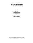
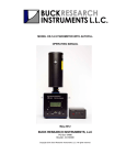
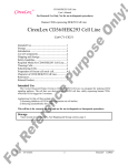
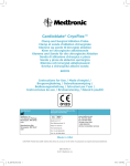
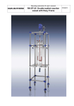
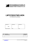
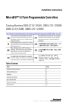
LC10
Liquid Nitrogen
Level Controller
User Manual
Teragon Research • 2518 26th Avenue • San Francisco, CA 94116
phone: 415-664-6814 • fax: 415-664-6745 • www.trgn.com
WARNING: THE LC10 CONTROLLER CONTAINS CMOS CIRCUITS
WHICH ARE SUSCEPTIBLE TO DAMAGE BY ELECTROSTATIC
DISCHARGE (ESD). STANDARD ESD HANDLING PRECAUTIONS
SHOULD BE OBSERVED WHEN INSTALLING THE CONTROLLER.
WARNING: TRACES ON THE LC10 CIRCUIT BOARD CAN CARRY
LETHAL VOLTAGES. INSTALLATION AND MAINTENANCE SHOULD
ONLY BE PERFORMED BY A QUALIFIED ELECTRICAL TECHNICIAN.
WHILE POWER IS APPLIED, CONTACT WITH THE CIRCUIT BOARD
CAN LEAD TO DAMAGE, INJURY OR DEATH.
WARNING: CONTACT WITH LIQUID NITROGEN OR COLD
NITROGEN GAS MAY CAUSE SERIOUS FROSTBITE OR BLINDNESS.
NITROGEN GAS CAN CAUSE RAPID SUFFOCATION; USE AND STORE
LIQUID NITROGEN ONLY IN WELL VENTILATED PLACES.
1. Overview
The LC10 Liquid Level Controller uses two LS10 Sensors to maintain the
nitrogen level in a cryogenic reservoir. The controller uses a solid-state relay to operate
an external cryogenic solenoid valve. A typical LC10 application is shown in figure 1.
The controller has been designed so that either LS10 sensor will function as the high (or
low) sensor. Filling will begin when both sensors have become dry and continue until
both sensors have become wet. As a safety feature, the controller will not initiate (or
continue) a fill operation if either sensor is unplugged.
CRYOGENIC
SOLENOID
VALVE
TRANSFER
LINE
LC10
CONTROLLER
LIQUID
NITROGEN
SUPPLY
DEWAR
LS10
SENSORS
FIGURE 1. A typical LC10 application.
As shown in figure 2, the LC10 circuit board is equipped with two jacks that
accept the LS10 sensor plugs. Screw terminals are used to make all other connections to
1
the LC10 circuit board. In addition to the power and valve terminals, the controller also
has STATUS and FILLING outputs as well as a TOGGLE input. The STATUS output
indicates that the sensors are installed and operating properly. If both sensors are
functioning, the STATUS output is connected to COMMON. Otherwise the STATUS
output flashes between COMMON and open to indicate a fault condition.
120 VAC
LS10
JACK
#1
VALVE
COMMON
TOGGLE
STATUS
FILLING
LS10
JACK
#2
+ 5VDC
FIGURE 2. The LC10 circuit board.
The FILLING output can be used by external equipment to monitor the LC10's
filling status. This open-collector output is connected to COMMON only when the solid
state relay is activated. The TOGGLE input permits external control over the filling
process. It can be used to change the controllers current state (waiting or filling) or to
override the controller.
The controller uses two LS10 sensors to monitor the liquid level within the
cryogenic reservoir. As shown in figure 3, each sensor has a sensing tip that is covered
by a splash guard. The sensing tip is connected to the sensor plug by cryoflex leads. The
sensor plug mates with the sensor jacks provided on the LC10 circuit board. Sensors are
available with 2, 3, or 4 foot leads.
FIGURE 3. The LS10 Sensor.
2
The LC10 is powered from 120VAC (230VAC optional) and is supplied as a
circuit board with screw terminals and mounting holes. Features of the LC10 include:
1) A watch dog timer for high reliability operation, 2) A metal-oxide-varistor (MOV) to
protect the controller from voltage spikes on the power mains, 3) an opto-isolated 'zerovolt' switching relay to prevent electrical noise, and 4) A regulated 5VDC power supply
that can be used to power external circuits such as lights or buzzers.
2. Installation
Proper site selection for the LC10 Controller is very important. The controller
should not be placed where liquid OR COLD VAPOR will fall on it. In particular, cold
exhaust vapors generated during the fill operation must be directed away from the
controller. The LC10 circuit board has four mounting holes that accommodate #6 bolts.
The circuit board should not be mounted flush against a conducting surface as this will
'short out' the traces on the bottom of the board: A 1/4-inch standoff is recommended
when mounting the LC10 board.
Position the LS10 sensors at the desired high and low setpoints within the LN2
reservoir. For proper operation, the sensors must not be permitted to move due to the
turbulence generated during the fill operation. Sensors should either be anchored in place
or shielded from the turbulence within a shroud or tube. Anchoring can be accomplished
using a length of stainless rod and nylon cable ties. Suitable materials for a shroud or
tube include metals, PTFE, FEP, and phenolic. Be aware that inserting a warm tube into
LN2 is hazardous; liquid will spout from the upper end of the tube due to the boiling that
occurs within the tube.
During normal operation, the solenoid is energized when both sensors become
dry; and filling continues until both sensors are wet. Note that both level sensors are
treated equivalently and either sensor can function as the high or low sensor. There is no
need to determine which sensor is used for the upper or the lower position. Simply place
the sensors at the desired high and low setpoints and then insert the sensor plugs into
either jack on the controller.
The remaining connections to the LC10 are made using the ten screw terminals on
the circuit board. The following table gives the names, abbreviations, and functions for
each of the terminals.
Terminal No.
1
2
3
4
5
6
7
8
9
10
Terminal Name
LINE HOT
LINE NEUTRAL
VALVE NEUTRAL
VALVE HOT
COMMON
TOGGLE
STATUS
FILLING
+5VDC
+5VDC
3
Abbreviation
LH
LN
VN
VH
C
T
S
F
5V
5V
Function
AC Input
AC Input
AC Output
AC Output
DC Ground
Logic Input
Logic Output
Logic Output
DC Output
DC Output
Connect the solenoid valve leads to the VH and VN terminals. Connect any
auxiliary circuits (lights, switched, etc.) to the appropriate input/output terminals.
Finally, connect the unenergized power leads to the LH and LN terminals: ensure that the
hot leg of the mains power is connected to the LH terminal. Apply power to the power
leads to begin automated filling of the LN2 reservoir.
3. Operation
When power is applied to the LC10 Controller, it first runs a diagnostic to
determine if both LS10 sensors are installed and functioning properly. The controller
checks if the sensors are shorted, unplugged, or excessively noisy. Within 0.4 seconds,
the STATUS signal will indicate if the sensors are operating properly (see section 3.3). If
both sensors are functioning properly, the LC10 begins analyzing their signals to
determine if the sensors are wet or dry. The first wet/dry determinations require 23
seconds from the application of power; after which, active level control begins.
If either LS10 sensor is damaged or unplugged, the LC10 will cease to control the
LN2 level until the problem is remedied. Power will no longer be routed to the VH
terminal, the FILLING signal will not be active, and the STATUS signal will indicate
which sensors are faulty. However, the controller can be forced to fill by using the
TOGGLE input (see section 3.5). Active level control will not resume until 23 seconds
after all faulty sensors have been corrected.
The LC10 determines if each sensor is wet or dry based on the different thermal
conductivities of liquid and gaseous nitrogen. This is done by biasing the sensor with a
small amount of heat input. If the sensor is submerged in LN2, the heat is conducted
away from the sensor with negligible temperature rise. However, if the sensor is not
submerged, a small but measurable temperature rise occurs at the end of the sensor.
The controller alternately energizes each sensor during 20 second intervals. This
minimizes the LN2 boil-off because only one LS10 sensor is active at a time. When
cooled to the temperature of liquid nitrogen, the total power dissipated by the sensors is
88 mW. This corresponds to a quiescent boil-off rate of 1 liter of LN2 every 3 weeks.
The fact that the sensors are energized intermittently does cause some latency in
the controller's response to LN2 level changes. The typical delay from when both sensor
become wet and the corresponding removal of the VALVE and FILLING signals is 14
seconds. The typical delay from when both sensor become dry and the corresponding
application of the VALVE and FILLING signals is 29 seconds.
3.1 The LINE and VALVE Terminals
The line terminals (LH and LN) provide power to the controller and should be
connected to the 120VAC mains. This line voltage is also routed to the valve terminals
(VH and VN) when the controller attempts to fill. The LN (LINE NEUTRAL) terminal
is connected directly to the VN (VALVE NEUTRAL) terminal on the LC10 circuit
board. The LH (LINE HOT) terminal is connected to the input of the control relay.
When the relay is closed by the controller, the voltage applied to LH appears on VH. It is
important to correctly connect LH to the hot side of the mains since only this side is
switched on an off by the controller.
3.2 The 5V and COMMON Terminals
The LC10 is equipped with a regulated 5VDC power supply that can be used to
4
power external circuits. This makes it particularly easy to add indicators (lights, buzzers)
to the controller's STATUS or FILLING outputs. The COMMON terminal is the ground
reference (0VDC) for the power supply. Up to 90mA may be drawn from the 5VDC
terminal and returned via the COMMON terminal. The COMMON terminal can also be
used to ground an external DC supply, if one is used with the STATUS or FILLING
outputs.
3.3 The STATUS Output
The STATUS output indicates if the sensors are installed and operating properly.
The STATUS signal is an active-low open-collector output. If both sensors are installed
and functioning properly, the STATUS output is grounded (i.e. connected to COMMON)
If the controller determines that either sensor is shorted, unplugged, or excessively noisy
then STATUS flashes between ground and open. The number of flashes per second
indicates which sensor is faulty: one flash per second for sensor #1, two flashes per
second for sensor #2, and three flashes per second if both sensors are faulty. As shown in
figure 4, a simple LED circuit connected between STATUS and 5V can be used to
observe the STATUS signal.
+ 5VDC
LED
STATUS
150 Ω
FIGURE 4. Using an LED to observe the STATUS output..
Alternately an audible alarm can be generated from the STATUS output using
either of the circuits in figure 5. The first circuit provides only the audible signal while
the second provides both audible and visible signals.
+ 5VDC
+ 5VDC
2 KΩ
STATUS
2 KΩ
150 Ω
BUZZER
2N3904
BUZZER
LED
2N3904
STATUS
1N4148
COMMON
1N4148
COMMON
BUZZER = International Comp. Corp. p/n BRT2821P-06 (Allied Elect. Stock No. 623-1931)
FIGURE 5. Circuits that generate audible signals from the STATUS output.
Since STATUS is an open-collector output, it can be used with external power
supplies in excess of 5VDC. The voltage applied to STATUS should not exceed 40VDC
relative to COMMON. The current sunk by STATUS should not exceed 150 mA and
should not dissipate more than 350 mW.
3.4 The FILLING Output
The FILLING output indicates if the controller is trying to fill the dewar by
5
applying power to the VALVE terminals. The FILLING output is an active-low opencollector output; it is grounded (i.e. connected to COMMON) while the controller is
filling. A simple LED circuit, connected between FILLING and 5V, can be used to
observe the FILLING signal, as shown in figure 6.
+ 5VDC
LED
FILLING
150 Ω
FIGURE 6. Using an LED to observe the FILLING output.
Since FILLING is an open-collector output, it can be used with external power
supplies in excess of 5VDC. The voltage applied to FILLING should not exceed 40VDC
relative to COMMON. The current sunk by FILLING should not exceed 150 mA and
should not dissipate more than 350 mW.
3.5 The TOGGLE Input
The TOGGLE input provides immediate external control over the filling process.
If the liquid level is between the two sensors, then momentarily shorting the TOGGLE
terminal to COMMON will cause the status of the controller to toggle from the filling
state to the waiting state or vice versa. If both sensors are dry, shorting TOGGLE to
COMMON will disable filling until TOGGLE is released from COMMON. Finally, If
both sensors are wet (or if either sensor is unplugged), TOGGLE can be used to override
the controller and force-fill the reservoir. Usually, a normally-open momentary switch is
wired between TOGGLE and COMMON as shown in figure 7.
TOGGLE
COMMON
FIGURE 7. A momentary switch can be used to activate the TOGGLE input.
4. Specifications
Power: 120VAC @ 3Amps, 50-60 Hz (230VAC optional)
Size: 3.13 in. (L) x 3.0 in. (W) x 1.5 in. (H)
Fill Relay: 120VAC @ 2.5Amps, Zero-volt switching (230VAC optional)
Required Sensors: LS10, 2 each
Output Signals: STATUS and FILLING, open-collector, active low
Max. Voltage: 40VDC relative to COMMON
Max. Current: 150 mA
Max. Power: 350 mW
Input Signal: TOGGLE, active low.
Output Power Supply: 5VDC @ 90mA max.
Screw Terminals: Accepts 14 to 30 AWG
Mounting Holes: 2.5 in. square pattern, 0.15 in. I.D.
Specifications are subject to change without notice.
6
5. Warranty
The LC10 Level Controller and LS10 Level Sensors are warranted to be free from
defects in materials and construction for 1 year from the date of purchase. Neither the
controller nor sensors contain any user serviceable parts and all warranty repairs must be
performed by Teragon.
Every effort has been made to ensure the accuracy and completeness of both this
manual and the LC10 system that it describes. Should you discover any error in either
the manual or the LC10 system, we would be most grateful to hear from you regarding
the oversight. Please contact us at tel: 415-664-6814, fax: 415-664-6745 or e-mail:
[email protected]. We thank you in advance for your assistance. The quality of our
products and the satisfaction of our customers are our two greatest concerns.
© 2003 Teragon Research
Firmware Rev. 2.2
7