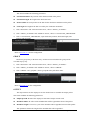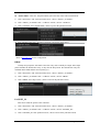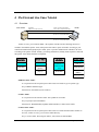
1
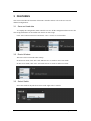
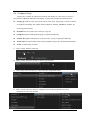
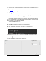
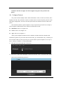
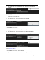
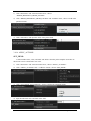
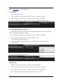
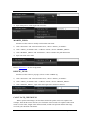
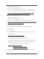
User Manual for POF Controller Contents User Manual for POF Controller ............................................................................... 1 Contents ............................................................................................................ 1 1 Introduction ........................................................................................................ 5 2 Glossary ............................................................................................................. 6 3 FEATURES ....................................................................................................... 7 3.1 Save and Load data ............................................................................... 7 3.2 Resize Window ..................................................................................... 7 3.3 Select Switch ........................................................................................ 7 3.4 Configure Group ................................................................................... 8 3.5 Configure Meter .................................................................................... 9 3.6 Configure Protocol .............................................................................. 10 3.7 Configure Metadata............................................................................. 11 3.8 Device Information ............................................................................. 12 3.9 Configure Flow Table ......................................................................... 13 3.10 Configure Flow Entry ......................................................................... 16 3.10.1 GOTO_TABLE ............................................................................ 17 3.10.2 GOTO_DIRECT_TABLE ............................................................ 18 3.10.3 METER ........................................................................................ 19 3.10.4 WRITE_METADATA ................................................................. 19 3.10.5 WRITE_METADATA_FROM_PACKET ................................... 19 3.10.6 APPLY_ACTIONS ...................................................................... 20 SET_FIELD ..................................................................................... 20 COUNTER ...................................................................................... 21 SET_FIELD_FROM_METADATA ................................................. 21 ADD_FIELD ................................................................................... 21 MODIFY_FIELD ............................................................................. 22 DELETE_FIELD ............................................................................. 22 2013-7-18 Page 1, Total 41 CALCULATE_CHECKSUM .......................................................... 22 GROUP............................................................................................ 23 OUTPUT ......................................................................................... 23 DROP .............................................................................................. 24 PACKET_IN .................................................................................... 24 4 IPv4 Unicast Use Case Tutorial ........................................................................ 26 4.1 Overview ............................................................................................ 26 4.2 Basic Configuration ............................................................................ 27 4.3 Add Tables .......................................................................................... 28 4.3.1 First Flow Table ........................................................................... 28 4.3.2 L2 Flow Table .............................................................................. 28 4.3.3 L3 Parse Flow Table ..................................................................... 29 4.3.4 L3 Flow Table .............................................................................. 29 4.4 Configure First Flow Table ................................................................. 30 4.4.1 Choose Table................................................................................ 30 4.4.2 Add Entry..................................................................................... 30 4.4.3 Configure Instruction/Action 1: GOTO_TABLE .......................... 30 4.5 Configure L2 Flow Table .................................................................... 30 4.5.1 Choose Table................................................................................ 30 4.5.2 Add Entry..................................................................................... 30 4.5.3 Configure Instruction/Action 1: WRITE_METADATA ............... 30 4.5.4 Configure Instruction/Action 2: GOTO_TABLE .......................... 31 4.6 Configure L3 Parse Flow Table ........................................................... 31 4.6.1 Choose Table................................................................................ 31 4.6.2 Add Entry..................................................................................... 31 4.6.3 Configure Instruction/Action 1: GOTO_TABLE .......................... 31 4.7 Configure L3 Flow Table .................................................................... 32 4.7.1 Choose Table................................................................................ 32 4.7.2 Add Entry..................................................................................... 32 4.7.3 Configure Instruction/Action 1: MODIFY_FIELD ....................... 32 4.7.4 Configure Instruction/Action 2: CALCULATE_CHECKSUM ..... 32 2013-7-18 Page 2, Total 41 4.7.5 Configure Instruction/Action 3: SET_FIELD ............................... 32 4.7.6 Configure Instruction/Action 4: OUTPUT .................................... 33 4.8 5 Run Use Case ...................................................................................... 33 IPv4 Multicast Use Case Tutorial ..................................................................... 34 5.1 Overview ............................................................................................ 34 5.2 Configure Group Table ....................................................................... 34 5.2.1 Create Group Table ...................................................................... 34 5.2.2 Configure Action 1: SET_FIELD ................................................. 35 5.2.3 Configure Action 2: OUTPUT ...................................................... 35 5.2.4 Configure Action 3: SET_FIELD ................................................. 35 5.2.5 Configure Action 4: OUTPUT ...................................................... 35 5.3 6 Configure Other Tables ....................................................................... 35 IPvX Use Case Tutorial .................................................................................... 36 6.1 Overview ............................................................................................ 36 6.2 Basic Configuration ............................................................................ 36 6.3 Add Tables .......................................................................................... 37 6.3.1 First Flow Table ........................................................................... 37 6.3.2 IPvX Parse Flow Table ................................................................. 38 6.3.3 IPvX Flow Table .......................................................................... 38 6.4 Configure First Flow Table ................................................................. 38 6.4.1 Choose Table................................................................................ 38 6.4.2 Add Entry..................................................................................... 39 6.4.3 Configure Instruction/Action 1: GOTO_TABLE .......................... 39 6.5 Configure IPvX Parse Flow Table ....................................................... 39 6.5.1 Choose Table................................................................................ 39 6.5.2 Add Entry..................................................................................... 39 6.5.3 Configure instruction/Action 1: GOTO_TABLE .......................... 39 6.6 Configure IPvX Flow Table ................................................................ 40 6.6.1 Choose Table................................................................................ 40 6.6.2 Add Entry..................................................................................... 40 6.6.3 Configure Instruction/Action 1: SET_FIELD ............................... 40 2013-7-18 Page 3, Total 41 6.6.4 Configure Instruction/Action 2: OUTPUT .................................... 40 6.7 2013-7-18 Run Use Case ...................................................................................... 41 Page 4, Total 41 1 Introduction This document describes the functions of the POF (Protocol Oblivious Forwarding). The content here is mainly about how to use the POF Controller GUI. The target readers are the researchers, developers, and telecom engineers who relate to the router, switch, especially the software defined network. The prototype supports most features of OpenFlow version 1.3, such as multiple tables, groups, meters, counters, instructions, actions, and metadata. Below are some differences between POF and OpenFlow version 1.3: 1) POF has no push-MPLS, push-PBB, and push-VLAN actions. These actions are replaced with the ADD_FIELD action. 2) POF has no pop-MPLS, pop-PBB, and pop-VLAN actions. These actions are replaced with the DELETE_FIELD action. 3) POF has no decrement TTL action. It is replaced with the MODIFY_FIELD action. 4) The SET_FIELD action in POF does not have any protocol-specific parameters like OFPXMT_OFB_IPV4_SRC and OFPXMT_OFB_TCP_SRC. Instead, the position and length of the filed in the packet are used as parameters. These differences reflect the protocol-oblivious nature of POF. The forwarding plane does not need to understand the protocol type and the meaning of each field. The protocol header fields are abstracted as simple offset and length tuples. 2013-7-18 Page 5, Total 41 2 Glossary Metadata: a register used to carry global information from one table to the next. MM: masked match table type. The matching key can have arbitrary bits masked as “don’t care” bits. A typical example is ACL table. LPM: longest prefix match table type. A typical example is IP FIB. EM: exact match table type. A typical example is L2 MAC table. VPN: virtual private network. VRF: VPN routing and forwarding. 2013-7-18 Page 6, Total 41 3 FEATURES This section describes the functions of the POF Controller. Please refer to the use cases for detailed configurations. 3.1 Save and Load data To simplify the configuration, POF controller can save all the configuration data into one file. The configuration data can be loaded from the file for later usage. Click “File” button in menu bar and choose “Save”/“Load” to save/load data. 3.2 Resize Window The GUI is full screen mode when startup. In full screen mode, click “File” and “Max Screen” to switch to max screen mode. In max screen mode, click “File” and “Full Screen” to switch to full screen mode. 3.3 Select Switch Select the switch in the pull-down menu on the right side of “Switch”. 2013-7-18 Page 7, Total 41 3.4 Configure Group A group entry contains an ordered list of actions. The ability for a flow entry to point to a group enables additional methods of forwarding. A group entry includes the following items: Group type: OFPGT_ALL: Execute all actions in the group. This group is used for multicast or broadcast forwarding. The options OFPGT_SELECT, OFPGT_INDIRECT, OFPGT_FF are not supported in POF. Switch ID: the device ID, select one device for group. Group ID: uniquely identifying the group, assigned automatically. Counter ID: updated when packets are processed by a group, assigned automatically. Action Num: the total number of the actions included in the group, cumulated automatically. Action: an ordered list of actions. 1) Click “Group” button in menu bar. 2) Click “Group” and “New Group” to add a new group table. 3) Click “group” and “Group Type”; choose the type in pull-down menu. 4) Click “Action” and “New Action”; configure actions of the group table. See action configurations in the later chapters. 2013-7-18 Page 8, Total 41 5) “ActionNum” and “GroupID” are automatically generated. Click “SAVE” button to submit all group configurations. Refer to Section 5.2 for the configuration. 3.5 Configure Meter A meter measures the rate of packets assigned to it and enables controlling the rate of those packets. Meters are attached directly to flow entries. Any flow entry can specify a meter in its instruction. The meter measures and controls the aggregated rate of all the flow entries to which it is attached. POF Controller only defines the meter as a rate limiter. The rate is the maximum output rate. POF Controller supports only the pass or drop action to the packet. When the output rate exceeds the rate specified by the meter, the packet is dropped. A meter includes the following items: Switch ID: the device ID, select one device for meter. Meter ID: uniquely identifying one meter; assigned automatically. Rate: The maximum output rate. The unit is kbps for the total frame length. 1) Click “Meter” button in menu bar. 2) Input the meter rate; click the 3) Click the icon to submit. Meter ID is automatically generated. icon if you want to delete a meter ID. 4) Click “SAVE” button to submit all meter configurations. 2013-7-18 Page 9, Total 41 Attention: The meter is single rate and we support only pass or drop action to the packet. 3.6 Configure Protocol One packet contains multiple fields. Each field includes a name, an offset (in bit unit), and a length (in bit unit). The packet has a name too, and the name can show the packet protocol. In the latter table configuration, it needs to select the packet name first and then select the fields of the packet. POF Controller defines a packet template as only one protocol layer header. For example, a packet template named Ethernet can be defined to include these fields: Destination: offset is 0, length is 48. Source: offset is 48, length is 48. Type: offset is 96, length is 16. Then a packet template named IPv4 can be defined to include all the IPv4 header fields. The Ethernet packets are processed in the first flow table, get a matched flow entry, and then go to the second flow table for IPv4 processing. We can also define a packet template to cover layer 2, layer 3, and layer 4 headers, even the payload data. 1) Click plus icon on the right side of “Protocol”. 2) Take turns to input name and length of each field, and click “OK” to submit the field. Offset of the field is automatically generated. 2013-7-18 Page 10, Total 41 3) Click “SAVE”, enter protocol name, and click “SAVE” to confirm protocol configuration. 4) Click the protocol name label in the line “Protocol” to see the protocol configuration. Refer to Section 4.2 for the configuration. 3.7 Configure Metadata POF-enabled switch contains multiple flow tables. The POF pipeline processing defines how packets interact with those flow tables. Metadata is in fact a register that is used to carry global information between tables. A table process can record a value in the metadata and the value can be used in another table process The metadata contains multiple fields. Each field is referenced by the following items: Name: user defined string for reference in instructions WRITE_METADATA and WRITE_METADATA_FROM_PACKET. A metadata field can also be used as a part of the match fields for the flow entry in the table. Offset: the field position in the metadata structure. Length: length of the field. The name is convenient for user configuration in GUI but meaningless to the POF-enabled switch. To reference a metadata field, the switch uses just the offset and the length. 2013-7-18 Page 11, Total 41 1) Double click “Metadata” label in the line “Protocol”. 2) Take turns to input name and length of each field, and click “OK” to submit the field. 3) Click “SAVE” confirm metadata configuration. 4) Click the “Metadata” label in the line “Protocol” to see metadata configuration. Refer to Section 4.2 for the configuration. Attention: Metadata definition is based on the switch. Different switches may have different metadata size and different field definition. In our switch, the first 32bit of metadata is fixed to keep some packet information automatically get from hardware before POF process; the other part is freely defined. 3.8 Device Information Click the icon in the lower right corner to display device information. Device information includes: Device info: all the devices connected to the controller. Port info: port information of all the devices. Each of the network cards will have a Port ID. 2013-7-18 Page 12, Total 41 Choose “POFEnable” in the rank “OpenFlow Enabled” to enable POF forwarding for a port. Flow table resource: the number of counter, meter, group, table, and table entry supported by each device. Recent error messages: Last 10error messages Packet-In messages: Last 10 packet-in messages. 3.9 Configure Flow Table A flow table descriptor includes the following fields: Table ID: uniquely identifying one table; assigned automatically. Table Name: a user defined string for reference in GUI. Switch ID: the device ID, select one device for flow table. Table Type: select one from MM, LPM, EM, and linear. The type determines how to execute the match process to get a flow entry in the table. For an MM table, the non wildcard bits in the match keys will be omitted in the match process. For an LPM table, the entry with the longest matching prefix with the key is returned. For an EM table, the match key has to be matched bit by bit. For a linear table, an index is used to retrieve a table entry. Table Size: size of the table; should not exceed the resource limit of the device. Key length: length of match key; calculated automatically after selecting the table fields. Table Field: the match fields selected to execute the match process against the table. The match key source is from packet data or from metadata. A direct table does not need to set 2013-7-18 Page 13, Total 41 the table field. Flow entry: a flow table contains a number of flow entries. A MM, LPM or EM table needs to execute the match process to find the matching flow entry. A direct table uses the entry index in the GOTO_DIRECT_TABLE instruction to retrieve the table entry directly. 1) Click the plus icon in the left of “Add New Table” add a new table. Click the diamond to configure the new table. 2) Click “Table Name”, input the table name, press “Enter” to confirm. 3) Click “Table Type”; choose the type in pull-down menu. 4) Click “Table Size”, input the table size, press “Enter” to confirm. 2013-7-18 Page 14, Total 41 5) Click “Table Field”, double click the key fields in the protocol window to choose table field (the selected field will turn green).The click order is the key order. Click “SUBMIT” to confirm table field configuration. “Key Length” is automatically generated. 6) Click “SUBMIT” in the bottom, choose “OK” in the pop-up window to confirm table configuration. 2013-7-18 Page 15, Total 41 Refer to use case for the configuration. 3.10 Configure Flow Entry A flow entry includes the following items: Flow entry ID: uniquely identifying one entry; assigned automatically. Priority: matching precedence of the flow entry. 0 is the lowest priority. The larger value means higher priority. Entry field: packet data or metadata fields to match against. These fields inherit from the table fields for a MM, LPM, and EM table. No entry field needs to be set for a linear table. An entry field contains ID, name, offset, length, value, and mask. The ID, name, offset, and length inherit from the table field which cannot be modified. Only the value and mask need to be set. Instruction: the pipeline processing instructions which will be executed when the flow entry is matched against packets. Counter: count the number of times the flow entry is matched; updated for each matching packet. Refer to use case for the configuration. 1) Click “Flow Entry”; click the plus icon in the left of “Flow Entries” to add an entry. 2) Click the new generated flow entry; click “Priority” and input priority of the entry. 2013-7-18 Page 16, Total 41 3) Click “Entry Field”; choose a key field, input hexadecimal value and mask of the key field. Input “0” for ignored match fields. 4) Click “Instruction”; configure instructions of the entry. See action configurations in the later chapters. 5) Click “SUBMIT” in the bottom, choose “OK” in the pop-up window to confirm entry configuration. To modify an existing flow entry, select the flow entry, click the right mouse button, and then select the item “Modify”. Select the item “Delete” to delete the flow entry. The figure below shows how to modify or delete a flow entry. 3.10.1 GOTO_TABLE This instruction is used to direct the packet to the next flow table in the pipeline process. The next flow table type should be MM, LPM, or EM. This instruction includes the following parameters: Next table ID: denotes the next flow table. Packet offset: denotes the number of bytes that should be skipped before extracting match fields from the packet. The match fields are denoted in the table field of the next table. 1) Click “Instruction” and “New Instruction Item”, choose “GOTO_TABLE”. 2013-7-18 Page 17, Total 41 2) Click “GOTO_TABLE” and then click “Next TableID”, choose a next table ID in the pull-down menu. 3) Click “Packet Offset (byte)”, input the packet offset. Refer to Section 4.3.3 for the configuration. 3.10.2 GOTO_DIRECT_TABLE This instruction is used to direct the packet to the next flow table in the pipeline process. The next flow table is a direct table. This instruction includes the following parameters: Next table ID: denotes the next flow table. Entry Index: denotes the index of the flow entry in the next flow table. Packet offset: denotes the number of bytes that should be skipped before extracting match fields from the packet. The match fields are denoted in the table field of the next table. 1) Click “Instruction” and “New Instruction Item”, choose “GOTO_DIRECT_TABLE”. 2) Click “GOTO_DIRECT_TABLE” and “nextTableID”, choose a next table ID in the pull-down menu. 2013-7-18 Page 18, Total 41 3) Click “Packet Offset (byte)”, input the packet offset. “Entry Index” is automatically generated. 3.10.3 METER Assign a meter ID for the flow entry. 1) Click “Instruction” and “New Instruction Item”, choose “METER”. 2) Click “METER” and “meterID (kbps)”, choose a meter rate in the pull-down menu. 3.10.4 WRITE_METADATA Set the metadata field value for the subsequent processing. The metadata field contains name, offset, length, and value. 1) Click “Instruction” and “New Instruction Item”, choose “WRITE_METADATA”. 2) Click “WRITE_METADATA” and “field name”, choose a field in the pull-down menu. 3) Click “field value”; input the decimal value of the field. Refer to Section 3.7 and 4.5.3. 3.10.5 WRITE_METADATA_FROM_PACKET Specify that the metadata field value is sourced from the input packet field. 2013-7-18 Page 19, Total 41 1) Click “Instruction” and “New Instruction Item”, choose “WRITE_METADATA_FROM_PACKET”. 2) Click “WRITE_METADATA_FROM_PACKET” and “metadata name”, choose a field in the pull-down menu. 3) Click “field offset” and input the offset of the packet field. 3.10.6 APPLY_ACTIONS SET_FIELD A field includes name, value, and mask. The field is from the packet template. Switches use this action to write a field with a new value. 1) Click “Instruction” and “New Instruction Item”, choose “APPLY_ACTIONS”. 2) Click “APPLY_ACTIONS” and “+ Add New Action”, choose “SET_FIELD”. 3) Click “SET_FIELD” and “FieldName”; choose a field in the pull-down menu. 4) Input hexadecimal value and mask of the field. 2013-7-18 Page 20, Total 41 Refer to Section 4.7.5 for the configuration. COUNTER Add a counter in the entry 1) Click “Instruction” and “New Instruction Item”, choose “APPLY_ACTIONS”. 2) Click “APPLY_ACTIONS” and “+ Add New Action”, choose “COUNTER”. 3) Click “COUNTER” and “counter ID”, the counter ID is automatically generated. SET_FIELD_FROM_METADATA The modified packet data field value can be from the metadata field. The packet field value will be replaced by the metadata field value. 1) Click “Instruction” and “New Instruction Item”, choose “APPLY_ACTIONS”. 2) Click “APPLY_ACTIONS” and “+ Add New Action”, choose “SET_FIELD_FROM_METADATA”. 3) Click “SET_FIELD_FROM_METADATA” and “FieldName”; choose a field in the pull-down menu. 4) Input the offset of the metadata field. ADD_FIELD Switches use this action to push tags, such as VLAN or MPLS tag. 1) Click “Instruction” and “New Instruction Item”, choose “APPLY_ACTIONS”. 2) Click “APPLY_ACTIONS” and “+ Add New Action”, choose “ADD_FIELD”. 3) Click “ADD_FIELD” and “Field Name”; input name of the new field. 2013-7-18 Page 21, Total 41 4) Input field position, field length and field value. MODIFY_FIELD Switches use this action to modify a field with an increment. 1) Click “Instruction” and “New Instruction Item”, choose “APPLY_ACTIONS”. 2) Click “APPLY_ACTIONS” and “+ Add New Action”, choose “MODIFY_FIELD”. 3) Click “MODIFY _FIELD” and “Field Name”; choose a field in the pull-down menu. 4) Input increment of the field. Refer to Section 4.7.3 for the configuration. DELETE_FIELD Switches use this action to pop tags, such as VLAN or MPLS tag. 1) Click “Instruction” and “New Instruction Item”, choose “APPLY_ACTIONS”. 2) Click “APPLY_ACTIONS” and “+ Add New Action”, choose “DELETE_FIELD”. 3) Click “DELETE _FIELD”; input offset and length of the field to be deleted. CALCULATE_CHECKSUM When a packet field changes, the checksum field of the packet needs to be updated. For example, when the IPv4 TTL decreases, the checksum of IPv4 needs to be updated. This action needs to set the offset, length of the checksum field, and the start position and the data range covered by the checksum calculation. 2013-7-18 Page 22, Total 41 This action includes the following parameters: Checksum Position: the position of the checksum field in the packet. Checksum Length: the length of the checksum field. Start Position: the start position of the data for the checksum calculation in the packet. Cal Length: the length of the data covered by the checksum calculation. 1) Click “Instruction” and “New Instruction Item”, choose “APPLY_ACTIONS”. 2) Click “APPLY_ACTIONS” and “Add New Action”, choose “CALCULATE_CHECKSUM”. 3) Click “CALCULATE_CHECKSUM”, input checksum position, checksum length, start position and cal length. Refer to Section 4.7.4 for the configuration. GROUP Attach one group entry to the flow entry. All the actions included in the group will be executed step by step. 1) Click “Instruction” and “New Instruction Item”, choose “APPLY_ACTIONS”. 2) Click “APPLY_ACTIONS” and “Add New Action”, choose “GROUP”. 3) Click “GROUP” and “groupID”; choose group ID in the pull-down menu. Refer to Section 5.2 for the configuration. OUTPUT The output action sets the output port. It also decides how to assemble the output packet. This action includes the following parameters: Output port ID: the ID of the output port. Port ID of output network card. Metadata Offset: the offset of the metadata that will be appended in front of the packet. Metadata Length: if not zero, a part of the metadata will be appended in front of the packet. This parameter denotes the length of the metadata that will be appended. . 2013-7-18 Page 23, Total 41 Packet Offset: if not zero, the packet data bytes before this value will be trimmed off. 1) Click “Instruction” and “New Instruction Item”, choose “APPLY_ACTIONS”. 2) Click “APPLY_ACTIONS” and “+ Add New Action”, choose “OUTPUT”. 3) Click “OUTPUT” and “outputPortID”; choose a port in the pull-down menu. 4) Input metadata offset (bit), metadata length (bit) and packet offset (byte). Refer to Section 4.7.6 for the configuration. DROP Usually an input packet will match some flow entry and eventually be output. If the input packet matches the default flow entry, it may take the drop action. The default flow entry has wildcard match fields and the lowest priority (0). 1) Click “Instruction” and “New Instruction Item”, choose “APPLY_ACTIONS”. 2) Click “APPLY_ACTIONS” and “+ Add New Action”, choose “DROP”. 3) Click “DROP” and “drop reason”; choose reason in the pull-down menu. PACKET_IN This action sends the packet to the controller. 1) Click “Instruction” and “New Instruction Item”, choose “APPLY_ACTIONS”. 2) Click “APPLY_ACTIONS” and “+ Add New Action”, choose “PACKET_IN”. 3) Click “PACKET_IN” and “packetin reason”; choose reason in the pull-down menu. 2013-7-18 Page 24, Total 41 2013-7-18 Page 25, Total 41 4 IPv4 Unicast Use Case Tutorial 4.1 Overview POF switch Port ID=1 MAC=01:02:03:04:05:06 MAC=07:08:09:0A:0B:0C IP=17.34.51.68(0x11223344) Port ID=2 MAC=12:34:56:78:9A:BC IP=68.51.34.17(0x44332211) Port ID=3 MAC=23:45:67:89:AB:CD IP=68.51.34.17(0x44332211) Tester In this use case, you’ll send an ETH + IPv4 packet to POF switch. Following actions are needed to forward this packet. First, lookup first flow table to parse L2 header. Second, get port control information through input port. Third, parse L3 packet and determine whether to do ACL according to the packet content. Finally, get routing information; modify fields in packet, and send this packet. Four tables should be configured: ETH First Flow Table L2 Flow Table Dmac+Type Input port GotoTable WriteMetadata (VpnID) GototTable (key=1) L3 Parse Flow Table L3 Flow Table VpnID+DIP V+IHL+TOS+Fl agsOffset+TTL +Protocol+SIP +DIP ModField (TTL-1) CalChecksum SetField (DMac) GotoTable Output ETH First Flow Table: It is equivalent to the L2 packet parse table. Parse L2 header to get L3 packet type. Keys: DMAC and ETH Type. Instructions: GotoTable (L2 Flow Table). L2 Flow Table: It is equivalent to the interface table. Get VpnID for next table. Keys: input port (from metadata). Instructions: WriteMetadata (VpnID) and GotoTable (L3 Parse Flow Table). L3 Parse Flow Table: It is equivalent to the L3 packet parse table. Parse L3 header and determine whether to do ACL, in this use case, go to L3 Flow Table directly. Keys: Version, IHL, TOS, Flags & Offset, TTL, Protocol, SIP and DIP. 2013-7-18 Page 26, Total 41 Instructions: GotoTable (L3 Flow Table). L3 Flow Table: It is equivalent to the FIB table. Get output port, modify packet and send packet. Keys: VpnID (from metadata) and DIP. Instructions: ModifyField (TTL-1), CalChecksum, SetField (Dmac) and Output. The configure process of the IPv4 unicast use case is as follows. 4.2 Basic Configuration First, select the switch in the pull-down menu on the right side of “Switch”. Second, configure protocol of the flow. 1) Click plus icon on the right side of “Protocol”. 2) Take turns to input name and length of each field, and click “OK” to submit the field. 3) Click “SAVE”, enter protocol name, and click “SAVE” to confirm protocol configuration. In this use case, protocol fields are: “Dmac”(48bit), “Smac”(48bit), “Type”(16bit), “V”(4bit), “IHL”(4bit), “TOS”(8bit), “TotalLength”(16bit), “ID”(16bit), “Flags&Offset”(16bit), “TTL”(8bit), “Protocol”(8bit), “Checksum”(16bit), “SIP”(32bit) and “DIP”(32bit). Protocol name is “ETH+IPv4”. 4) Click the protocol name label in the line “Protocol” to see the protocol configuration. Last, configure metadata of the flow. 1) Double click “Metadata” label in the line “Protocol”. 2) Take turns to input name and length of each field, and click “OK” to submit the field. In this use case, metadata fields are: “Packet Length” (16bit), “Input port” (8bit), “Rsvd” (8bit), “VpnID” (16bit). 3) Click “SAVE” confirm metadata configuration. 4) Click the “Metadata” label in the line “Protocol” to see metadata configuration. Packet Length is a fixed field for packet length in bytes, and is automatically get from hardware before POF process in our switch. Input port is a fixed field for port ID of packet input, and is automatically get from hardware before POF process in our switch. VpnID is a freely defined field for VRF ID share by IPv4 and IPv6. 2013-7-18 Page 27, Total 41 4.3 Add Tables 4.3.1 First Flow Table 1) Click the plus icon in the left of “Add New Table” add a new table. Click the diamond to configure the new table. First Flow Table name is fixed to “FirstEntryTable”. 2) Click “Table Type”; choose the type in pull-down menu. 3) Click “Table Size”, input the table size, press “Enter” to confirm. 4) Click “Table Field”, double click the key fields in the protocol window to choose table field (the selected field will turn green).The click order is the key order. Click “SUBMIT” to confirm table field configuration. “Key Length” is automatically generated. In this use case, FirstEntryTable size is “128”. FirstEntryTable type is “OF_MM_TABLE”. FirstEntryTable fields are “Dmac” and “Type”. 5) Click “SUBMIT” in the bottom, choose “OK” in the pop-up window to confirm table configuration. 4.3.2 L2 Flow Table 1) Click the plus icon in the left of “Add New Table” add a new table. Click the diamond to configure the new table. 2) Click “Table Name”, input the table name, press “Enter” to confirm. 3) Click “Table Type”; choose the type in pull-down menu. 4) Click “Table Size”, input the table size, press “Enter” to confirm. 5) Click “Table Field”, double click the key fields in the protocol window to choose table field (the selected field will turn green).The click order is the key order. Click “SUBMIT” to confirm table field configuration. “Key Length” is automatically generated. In this use case, L2 Flow Table name is “L2 Flow Table”. L2 Flow Table size is “128”. L2 Flow Table type is “OF_MM_TABLE”. L2 Flow Table field is “Input Port” in metadata. 6) Click “SUBMIT” in the bottom, choose “OK” in the pop-up window to confirm table configuration. 2013-7-18 Page 28, Total 41 4.3.3 L3 Parse Flow Table 1) . Click the plus icon in the left of “Add New Table” add a new table. Click the diamond to configure the new table. 2) Click “Table Name”, input the table name, press “Enter” to confirm. 3) Click “Table Type”; choose the type in pull-down menu. 4) Click “Table Size”, input the table size, press “Enter” to confirm. 5) Click “Table Field”, double click the key fields in the protocol window to choose table field (the selected field will turn green).The click order is the key order. Click “SUBMIT” to confirm table field configuration. “Key Length” is automatically generated. In this use case, L2 Flow Table name is “L3 Parse Flow Table”. L2 Flow Table size is “128”. L2 Flow Table type is “OF_MM_TABLE”. L2 Flow Table fields are “V”, “IHL”, “TOS”, “Flags & Offset”, “TTL”, “Protocol”, “SIP” and “DIP”. 6) Click “SUBMIT” in the bottom, choose “OK” in the pop-up window to confirm table configuration. 4.3.4 L3 Flow Table 1) Click the plus icon in the left of “Add New Table” add a new table. Click the diamond to configure the new table. 2) Click “Table Name”, input the table name, press “Enter” to confirm. 3) Click “Table Type”; choose the type in pull-down menu. 4) Click “Table Size”, input the table size, press “Enter” to confirm. 5) Click “Table Field”, double click the key fields in the protocol window to choose table field (the selected field will turn green).The click order is the key order. Click “SUBMIT” to confirm table field configuration. “Key Length” is automatically generated. In this use case, L2 Flow Table name is “L3 Flow Table”. L2 Flow Table size is “128”. L2 Flow Table type is “OF_LPM_TABLE”. L2 Flow Table fields are “VPNID” in metadata and “DIP”. 6) Click “SUBMIT” in the bottom, choose “OK” in the pop-up window to confirm table configuration. 2013-7-18 Page 29, Total 41 4.4 Configure First Flow Table 4.4.1 Choose Table Click the diamond of First Flow Table. 4.4.2 Add Entry 1) Click “Flow Entry”; click the plus icon in the left of “Flow Entries” to add an entry. 2) Click the new generated flow entry; click “Priority” and input priority of the entry. 3) Click “Entry Field”; choose a key field, input value and mask of the key field. Input “0” for ignored match fields. In this entry, entry priority is “1”. Entry field “DMAC”: value = “0” and mask = “0” Entry field “Type”: value = “0800” and mask = “ffff”. 4.4.3 Configure Instruction/Action 1: GOTO_TABLE 1) Click “Instruction” and “New Instruction Item”, choose “GOTO_TABLE”. 2) Click “GOTO_TABLE” and then click “Next TableID”, choose “L2 Flow Table” in the pull-down menu, create connection between First Flow Table and L2 Flow Table. 3) Click “Packet Offset (byte)”, input the packet offset with the value “0”. 4) Click “Submit” in the bottom to confirm the configuration of First Flow Table. 4.5 Configure L2 Flow Table 4.5.1 Choose Table Click the diamond of L2 Flow Table. 4.5.2 Add Entry 1) Click “Flow Entry”; click the plus icon in the left of “Flow Entries” to add an entry. 2) Click the new generated flow entry; click “Priority” and input priority of the entry. 3) Click “Entry Field”; choose a key field, input value and mask of the key field. Input “0” for ignored match fields. In this entry, entry priority is “1”. Entry field “Input Port”: value = “01” and mask = “ff”. 4.5.3 Configure Instruction/Action 1: WRITE_METADATA 1) Click “Instruction” and “New Instruction Item”, choose “WRITE_METADATA”. 2) Click “WRITE_METADATA” and “field name”, choose a field in the pull-down menu. 2013-7-18 Page 30, Total 41 3) Click “field value”; input the value of the field. In this instruction, field name is “VPNID”. Field value is “0256”. Attention: “Input Port” is based on your switch. Different switches may have different network cards and different port ID. Here, port ID of network card that packet input is “1”. “VpnID” value “0256” is decimal, equals to hexadecimal “0100” in 4.7.2. 4.5.4 Configure Instruction/Action 2: GOTO_TABLE 1) Click “Instruction” and “New Instruction Item”, choose “GOTO_TABLE”. 2) Click “GOTO_TABLE” and then click “Next TableID”, choose “L3 Parse Flow Table” in the pull-down menu, create connection between L2 Flow Table and L3 Parse Flow Table. 3) Click “Packet Offset (byte)”, input the packet offset with the value “0”. 4) Click “Submit” in the bottom to confirm the configuration of L2 Flow Table. 4.6 Configure L3 Parse Flow Table 4.6.1 Choose Table Click the diamond of L3 Parse Flow Table. 4.6.2 Add Entry 1) Click “Flow Entry”; click the plus icon in the left of “Flow Entries” to add an entry. 2) Click the new generated flow entry; click “Priority” and input priority of the entry. 3) Click “Entry Field”; choose a key field, input value and mask of the key field. Input “0” for ignored match fields. In this entry, entry priority is “1”. Entry field “V”: value = “4” and mask = “f”. Entry field “IHL”: value = “5” and mask = “f”. Other entry fields: value = “0” and mask = “0” 4.6.3 Configure Instruction/Action 1: GOTO_TABLE 1) Click “Instruction” and “New Instruction Item”, choose “GOTO_TABLE”. 2) Click “GOTO_TABLE” and then click “Next TableID”, choose “L3 Flow Table” in the pull-down menu, create connection between L3 Parse Flow Table and L3 Flow Table. 3) Click “Packet Offset (byte)”, input the packet offset with the value “0”. 4) Click “Submit” in the bottom to confirm the configuration of L3 Parse Flow Table. 2013-7-18 Page 31, Total 41 4.7 Configure L3 Flow Table 4.7.1 Choose Table Click the diamond of L3 Flow Table. 4.7.2 Add Entry 1) Click “Flow Entry”; click the plus icon in the left of “Flow Entries” to add an entry. 2) Click the new generated flow entry; click “Priority” and input priority of the entry. 3) Click “Entry Field”; choose a key field, input value and mask of the key field. Input “0” for ignored match fields. In this entry, entry priority is “1”. Entry field “VPNID”: value = “0100” and mask = “ffff”. Entry field “DIP”: value = “44332211” and mask = “ffffffff”. Attention: “VpnID” value “0100” is hexadecimal, equals to decimal “0256” in 4.5.3. 4.7.3 Configure Instruction/Action 1: MODIFY_FIELD 1) Click “Instruction” and “New Instruction Item”, choose “APPLY_ACTIONS”. 2) Click “APPLY_ACTIONS” and “+ Add New Action”, choose “MODIFY_FIELD”. 3) Click “MODIFY _FIELD” and “Field Name”; choose a field in the pull-down menu. 4) Input increment of the field. In this instruction, field name is “TTL”. Increment is “-1”. 4.7.4 Configure Instruction/Action 2: CALCULATE_CHECKSUM 1) Click “Instruction” and “New Instruction Item”, choose “APPLY_ACTIONS”. 2) Click “APPLY_ACTIONS” and “Add New Action”, choose “CALCULATE_CHECKSUM”. 3) Click “CALCULATE_CHECKSUM”, input checksum position, checksum length, start position and cal length. In this instruction, checksum position is “192”. Checksum length is “16”. Start position is “112”. Cal length is “160”. 4.7.5 Configure Instruction/Action 3: SET_FIELD 1) Click “Instruction” and “New Instruction Item”, choose “APPLY_ACTIONS”. 2013-7-18 Page 32, Total 41 2) Click “APPLY_ACTIONS” and “+ Add New Action”, choose “SET_FIELD”. 3) Click “SET_FIELD” and “FieldName”; choose a field in the pull-down menu. 4) Input value and mask of the field. In this instruction, field name is “DMAC”. Field value is “123456789ABC”. Field mask is “ffffffffffff”. Attention: “DMAC” s based on your test environment; here is the Mac address of Tester. 4.7.6 Configure Instruction/Action 4: OUTPUT 1) Click “Instruction” and “New Instruction Item”, choose “APPLY_ACTIONS”. 2) Click “APPLY_ACTIONS” and “+ Add New Action”, choose “OUTPUT”. 3) Click “OUTPUT” and “outputPortID”; choose a port in the pull-down menu. 4) Input metadata offset (bit), metadata length (bit) and packet offset (byte). In this instruction, output port ID is “2”. Metadata offset is “0”. Metadata length is “0”. Packet offset is “0”. 5) Click “Submit” in the bottom to confirm the configuration of L3 Flow Table. Attention: “OutputPortID” is based on your switch. Different switches may have different network cards and different port ID. Here, port ID of network card that packet output is “2”. 4.8 Run Use Case Use tester to send following packet to POF switch. Eth Dmac(48) 010203040506 ID(16) 0000 Type(16) 0800 IPv4 Flags_Offset(16) TTL(8) Protocol(8) checksum(16 0000 64 06 XXXX 2013-7-18 Smac(48) 0708090A0B0C V(4) 4 IHL(4) 5 SIP(32) 11223344 IPv4 TOS(8) 00 TotalLength(16) XXXX DIP(32) 44332211 Page 33, Total 41 5 IPv4 Multicast Use Case Tutorial 5.1 Overview In this use case, POF switch should have at least two network cards. The port IDs are “1” and “2”. Send an ETH + IPv4 packet to POF switch, switch will multicast the packet from these output ports. ETH First Flow Table L2 Flow Table Dmac+Type Input port GotoTable WriteMetadata (VpnID) GototTable (key=1) L3 Parse Flow Table L3 Flow Table VpnID+DIP Group Table V+IHL+TOS+Fl agsOffset+TTL +Protocol+SIP +DIP ModField (TTL-1) SetField (DMac) CalChecksum Output GotoTable Group SetField (DMac) Output ETH First Flow Table, L2 Flow Table, L3 Parse Flow Table are same as IPv4 unicast use case. L3 Flow Table is similar to IPv4 unicast use case in 4.7, has different instructions. Group table is used for multicast, encapsulate different L2 headers, choose different output channels to send packet. Actions: Set Field (Dmac), Output (Port1), Set Field (Dmac) and Output (port2). Configure process of Ipv4 multicast use case is as follows. 5.2 Configure Group Table Configuration of packet, metadata and meter is same as IPv4 unicast use case. 5.2.1 Create Group Table 1) Click “Group” button in menu bar. 2) Click “Group” and “New Group” to add a new group table. 3) Click “group” and “Group Type”; choose the type in pull-down menu. In this use case, Group Table type is “OFPGT_ALL”. 4) Click “Action” and “New Action”; configure actions of the group table. See action configurations in Section 5.2.2 to Section 5.2.5. 5) “ActionNum” and “GroupID” are automatically generated. Click “SAVE” button to submit all group configurations. 2013-7-18 Page 34, Total 41 5.2.2 Configure Action 1: SET_FIELD 1) Click “Action” and “New Action”, choose “SET_FIELD”. 2) Click “SET_FIELD” and “FieldName”; choose a field in the pull-down menu. 3) Input value and mask of the field. In this action, field name is “DMAC”. Field value is “123456789ABC”. Field mask is “ffffffffffff”. 5.2.3 Configure Action 2: OUTPUT 1) Click “Action” and “New Action”, choose “OUTPUT”. 2) Click “OUTPUT” and “outputPortID”; choose a port in the pull-down menu. 3) Input metadata offset (bit), metadata length (bit) and packet offset (byte). In this action, output port ID is “2”. Metadata offset is “0”. Metadata length is “0”. Packet offset is “0”. 5.2.4 Configure Action 3: SET_FIELD Same as action1, set field “DMAC”, Value is “23456789ABCD”, mask is “ffffffffffff”. 5.2.5 Configure Action 4: OUTPUT Same as action2, output port is “3”. Attention: “DMAC” is based on your test environment; here is the Mac address of Tester. “OutputPortID” is based on your switch. Different switches may have different network cards and different port ID. Here, ports ID of network card that packet output are “2” and “3”. 5.3 Configure Other Tables Configuration of First Flow Table, L2 Flow Table, L3 Parse Flow Table and L3 Flow Table is same as IPv4 unicast use case. The only difference is L3 Flow Table doesn’t have instruction/action “SET_FIELD”, “OUTPUT”. The third instruction is “Group” and the configuration is as follows. 1) Click “Instruction” and “New Instruction Item”, choose “APPLY_ACTIONS”. 2) Click “APPLY_ACTIONS” and “Add New Action”, choose “GROUP”. 3) Click “GROUP” and “groupID”; choose group ID “1” in the pull-down menu, create connection between L3 Flow Table and group table. 2013-7-18 Page 35, Total 41 6 IPvX Use Case Tutorial 6.1 Overview POF switch Port ID=1 MAC=01:02:03:04:05:06 MAC=07:08:09:0A:0B:0C IP=0x1122334455667788 Port ID=2 MAC=12:34:56:78:9A:BC IP=0x8877655544332211 Tester In this use case, you’ll send an ETH + IPvX packet to POF switch. Following actions are needed to forward this packet. First, lookup first flow table to parse L2 header. Second, parse IPvX packet. Finally, get routing information; modify fields in packet, and send this packet. Three tables should be configured: ETH First Flow Table IPvX Parse Flow Table IPvX Flow Table Dmac+Type DIP+SIP+Proto col DIP GotoTable GotoTable SetField (DMac) Output ETH First Flow Table: Keys: DMAC and ETH Type. Instructions: GotoTable (IPvX parse flow table). IPvX Parse Flow Table: Keys: DIP, SIP and Protocol. Instructions: GotoTable (IPvX flow table). IPvX Flow Table: Keys: DIP. Instructions: SetField (Dmac) and Output. The configure process of the IPvX use case is as follows. Reference the POF tutorial. 6.2 Basic Configuration First, select the switch in the pull-down menu on the right side of “Switch”. 2013-7-18 Page 36, Total 41 Second, configure protocol of the flow. 1) Click plus icon on the right side of “Protocol”. 2) Take turns to input name and length of each field, and click “OK” to submit the field. 3) Click “SAVE”, enter protocol name, and click “SAVE” to confirm protocol configuration. In this use case, protocol fields are: “Dmac”(48bit), “Smac”(48bit), “Type”(16bit), “DIP”(64bit), “SIP”(64bit), “Protocol”(16). Protocol name is “ETH+IPvX”. 4) Click the protocol name label in the line “Protocol” to see the protocol configuration. Last, configure metadata of the flow. 1) Double click “Metadata” label in the line “Protocol”. 2) Take turns to input name and length of each field, and click “OK” to submit the field. In this use case, no user defined field is needed, so metadata fields are fixed fields: “Packet Length” (16bit), “Input port” (8bit), “Rsvd” (8bit). 3) Click “SAVE” confirm metadata configuration. 4) Click the “Metadata” label in the line “Protocol” to see metadata configuration. 6.3 Add Tables 6.3.1 First Flow Table 1) Click the plus icon in the left of “Add New Table” add a new table. Click the diamond to configure the new table. First Flow Table name is fixed to “FirstEntryTable”. 2) Click “Table Type”; choose the type in pull-down menu. 3) Click “Table Size”, input the table size, press “Enter” to confirm. 4) Click “Table Field”, double click the key fields in the protocol window to choose table field (the selected field will turn green).The click order is the key order. Click “SUBMIT” to confirm table field configuration. “Key Length” is automatically generated. In this use case, FirstEntryTable size is “128”. FirstEntryTable type is “OF_MM_TABLE”. FirstEntryTable fields are “Dmac” and “Type”. 5) Click “SUBMIT” in the bottom, choose “OK” in the pop-up window to confirm table configuration. 2013-7-18 Page 37, Total 41 6.3.2 IPvX Parse Flow Table 1) Click the plus icon in the left of “Add New Table” add a new table. Click the diamond to configure the new table. 2) Click “Table Name”, input the table name, press “Enter” to confirm. 3) Click “Table Type”; choose the type in pull-down menu. 4) Click “Table Size”, input the table size, press “Enter” to confirm. 5) Click “Table Field”, double click the key fields in the protocol window to choose table field (the selected field will turn green).The click order is the key order. Click “SUBMIT” to confirm table field configuration. “Key Length” is automatically generated. In this use case, IPvX Parse Flow Table name is “IPvX Parse Flow Table”. IPvX Parse Flow Table size is “128”. IPvX Parse Flow Table type is “OF_MM_TABLE”. IPvX Parse Flow Table fields are “DIP”, “SIP” and “Protocol”. 6) Click “SUBMIT” in the bottom, choose “OK” in the pop-up window to confirm table configuration. 6.3.3 IPvX Flow Table 1) Click the plus icon in the left of “Add New Table” add a new table. Click the diamond to configure the new table. 2) Click “Table Name”, input the table name, press “Enter” to confirm. 3) Click “Table Type”; choose the type in pull-down menu. 4) Click “Table Size”, input the table size, press “Enter” to confirm. 5) Click “Table Field”, double click the key fields in the protocol window to choose table field (the selected field will turn green).The click order is the key order. Click “SUBMIT” to confirm table field configuration. “Key Length” is automatically generated. In this use case, IPvX Flow Table name is “IPvX Flow Table”. IPvX Flow Table size is “128”. IPvX Flow Table type is “OF_LPM_TABLE”. IPvX Flow Table field is “DIP”. 6) Click “SUBMIT” in the bottom, choose “OK” in the pop-up window to confirm table configuration. 6.4 Configure First Flow Table 6.4.1 Choose Table Click the diamond of First Flow Table. 2013-7-18 Page 38, Total 41 6.4.2 Add Entry 1) Click “Flow Entry”; click the plus icon in the left of “Flow Entries” to add an entry. 2) Click the new generated flow entry; click “Priority” and input priority of the entry. 3) Click “Entry Field”; choose a key field, input value and mask of the key field. Input “0” for ignored match fields. In this entry, entry priority is “1”. Entry field “DMAC”: value = “0” and mask = “0” Entry field “Type”: value = “0888” and mask = “ffff”. 6.4.3 Configure Instruction/Action 1: GOTO_TABLE 1) Click “Instruction” and “New Instruction Item”, choose “GOTO_TABLE”. 2) Click “GOTO_TABLE” and then click “Next TableID”, choose “IPvX Parse Flow Table” in the pull-down menu, create connection between First Flow Table and IPvX Parse Flow Table. 3) Click “Packet Offset (byte)”, input the packet offset with the value “0”. 4) Click “Submit” in the bottom to confirm the configuration of First Flow Table. 6.5 Configure IPvX Parse Flow Table 6.5.1 Choose Table Click the diamond of IPvX Parse Flow Table. 6.5.2 Add Entry 1) Click “Flow Entry”; click the plus icon in the left of “Flow Entries” to add an entry. 2) Click the new generated flow entry; click “Priority” and input priority of the entry. 3) Click “Entry Field”; choose a key field, input value and mask of the key field. Input “0” for ignored match fields. In this entry, entry priority is “1”. Entry field “Protocol”: value = “0999” and mask = “ffff”. Other entry fields: value = “0” and mask = “0”. 6.5.3 Configure instruction/Action 1: GOTO_TABLE 1) Click “Instruction” and “New Instruction Item”, choose “GOTO_TABLE”. 2) Click “GOTO_TABLE” and then click “Next TableID”, choose “IPvX Flow Table” in the pull-down menu, create connection between IPvX Parse Flow Table and IPvX Flow Table. 3) Click “Packet Offset (byte)”, input the packet offset with the value “0”. 4) Click “Submit” in the bottom to confirm the configuration of IPvX Parse Flow Table. 2013-7-18 Page 39, Total 41 6.6 Configure IPvX Flow Table 6.6.1 Choose Table Click the diamond of IPvX Flow Table. 6.6.2 Add Entry 1) Click “Flow Entry”; click the plus icon in the left of “Flow Entries” to add an entry. 2) Click the new generated flow entry; click “Priority” and input priority of the entry. 3) Click “Entry Field”; choose a key field, input value and mask of the key field. Input “0” for ignored match fields. In this entry, entry priority is “1”. Entry field “DIP”: value = “1122334455667788” and mask = “ffffffffffffffff”. 6.6.3 Configure Instruction/Action 1: SET_FIELD 1) Click “Instruction” and “New Instruction Item”, choose “APPLY_ACTIONS”. 2) Click “APPLY_ACTIONS” and “+ Add New Action”, choose “SET_FIELD”. 3) Click “SET_FIELD” and “FieldName”; choose a field in the pull-down menu. 4) Input value and mask of the field. In this instruction, field name is “DMAC”. Field value is “123456789ABC”. Field mask is “ffffffffffff”. Attention: “DMAC” is based on your test environment; here is the Mac address of Tester. 6.6.4 Configure Instruction/Action 2: OUTPUT 1) Click “Instruction” and “New Instruction Item”, choose “APPLY_ACTIONS”. 2) Click “APPLY_ACTIONS” and “+ Add New Action”, choose “OUTPUT”. 3) Click “OUTPUT” and “outputPortID”; choose a port in the pull-down menu. 4) Input metadata offset (bit), metadata length (bit) and packet offset (byte). In this instruction, output port ID is “2”. Metadata offset is “0”. Metadata length is “0”. Packet offset is “0”. 5) Click “Submit” in the bottom to confirm the configuration of L3 Flow Table. Attention: “OutputPortID” is based on your switch. Different switches may have different network cards and different port ID. Here, port ID of network card that packet output is “2”. 2013-7-18 Page 40, Total 41 6.7 Run Use Case Use tester to send following packet to POF switch. Eth IPvX Dmac(48) Smac(48) Type(16) DIP(64) SIP(64) Protocol(16) 010203040506 0708090A0B0C 0888 1122334455667788 8877665544332211 0999 2013-7-18 Page 41, Total 41