1
SATCOM-On-The-Move User Manual
For the SOTM RIT Project
SATCOM-On-The-Move User Manual
Page 1 of 6
Table of Contents
Introduction .................................................................................................................................................. 3
Required Programs ................................................................................................................................... 3
Required Documents ................................................................................................................................ 3
Required Equipment ................................................................................................................................. 3
Powering Up and Calibration ........................................................................................................................ 3
Choosing a Point ........................................................................................................................................... 4
Calibrate the Geo-PNT .................................................................................................................................. 4
Error Test ...................................................................................................................................................... 5
GPS Loss Error Test ....................................................................................................................................... 5
Copy Video from Camera .............................................................................................................................. 5
Run Through the Error Measurement Program............................................................................................ 5
Charging the System ..................................................................................................................................... 5
SATCOM-On-The-Move User Manual
Page 2 of 6
Introduction
This document explains the usage of the SOTM box. The purpose of the SOTM box is to direct the mount
to point towards a given ECEF location.
Required Programs
Arduino 1.6.3+
o PNT_Control.ino
Visual Studio
o opencvObjectTracking.sln
main.cpp
Required Documents
Assembly.docx
Required Equipment
A computer (Windows OS with Arduino/Visual Studio programs)
USB to micro-USB (Male to Male) cable
USB to mini-USB (Male to Male) cable
SOTM Box
Camera
Powering Up and Calibration
The system must first be fully charged and powered on to begin usage (See Charging the System section
for how to fully charge the system).
1. Once fully charged, the SOTM box should be placed in vehicle stand, or in a mobile environment
where the GPS antenna has a full view of GPS satellites.
2. Press the Power switch (blue button located on the front side of the enclosure), and ensure that
this switch is locked in.
3. Allow up to 2 minutes for the Geo-PNT to initialize and receive its current positioning data.
4. (Optional) If it is determined that through usage of the SOTM box, the GPS antenna might be
out of view of the GPS satellites at any time during the run, a calibration of the inertial
measurement sensors is required. To perform this calibration, follow these steps:
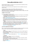
a. Point the vehicle due North within 2 degrees.
b. Begin driving North and make a 90-degree turn in the West direction, and begin driving
in a square as indicated in Figure 1.
c. The next turn should be another 90-degree turn in the South direction, likewise then
another 90-degree turn in the East direction, and finally back to where you started with
a final 90-degree turn in the North direction.
d. Continue this square pattern through 4 to 6 loops to ensure the queue within the IMUs
is filled with valid N-W-S-E data.
SATCOM-On-The-Move User Manual
Page 3 of 6
West
North
South
East
Figure 1: Example Square to be Driven (RIT Campus Parking Lot H)
Choosing a Point
There are many ways to choose a point. It must be in ECEF for the Arduino program to use and the
microcontroller must be reprogrammed.
1. Choose a point in ECEF.
2. Open the PNT_Control.ino file with the Arduino program.
3. Edit line 27 to set the variable “focus” to the point at which to direct the mount
a. Ex: double focus[] = {996455, -4557908, 4334643}; // Ellingson Estimation
b. Alternatively, comment out the line (place “//” in front) and copy over a new line like
the one above to save those coordinates for later use.
4. Remove the Serial shield from the microcontroller while it is not powered
5. Connect the microcontroller (the programming port is the one closest to the power connector)
to the computer and install the drivers if it is the time connecting
6. Set-up the Arduino programmer to connect to the microcontroller
a. Click “Tools” > “Board” > “Arduino Due (Programming Port)”
b. Click “Tools” > “Port” > COM## (where ## stands for the com port the Arduino is
connected to)
7. Click “File” > “Upload” to transfer the program onto the microcontroller
8. After receiving the “Upload Done.” message at the end of the process, the microcontroller can
be disconnected
9. Reconstruct the Box starting at section 2.1.39 according to the Assembly procedure.
Calibrate the Geo-PNT
The Geo-PNT has very specific requirements as a startup sequence. This calibration procedure requires a
perfectly rectangular section of road that lines up with North, South, East, and West. It must be fairly
large and it helps if sections of the road are sloped.
1. Place the Geo-PNT into the vehicle according to section 3.3.3 of the Assembly procedure.
2. Drive the vehicle to point North at the South-East most point in the rectangle.
3. Start the Geo-PNT and wait 15-20 seconds for the Geo-PNT to finish its internal start-up
procedures.
SATCOM-On-The-Move User Manual
Page 4 of 6
4. Begin to drive the vehicle and drive clockwise through the rectangle in a N-E-S-W pattern.
a. Continue the pattern for 7 - 10 loops, depending on the size of the rectangle.
5. At this point the system should be fully calibrated and pointing in the right direction.
Error Test
Start the camera by pushing the On/Off button and open the lens by toggling the lens cover switch.
Once it has finished turning on (indicated by a live display of the camera’s point of view), push the red
record button. Drive around the focus point until there is sufficient video from which to extract data.
Stop the camera recording by pushing the red record button again. Turn off the camera by pushing the
On/Off button and toggle the lens cover switch to protect the lens.
GPS Loss Error Test
Start the camera by pushing the On/Off button and open the lens by toggling the lens cover switch.
Once it has finished turning on (indicated by a live display of the camera’s point of view), push the red
record button. Disconnect the GPS antenna and indicate when the disconnection happened on the video
for reference. Drive around the focus point until there is sufficient video from which to extract data.
Stop the camera recording by pushing the red record button again. Turn off the camera by pushing the
On/Off button and toggle the lens cover switch to protect the lens.
Copy Video from Camera
Connect the camera to the computer using the mini-USB cable. Once the drivers have completed
installing, the video files are readily available from the “My Computer” folder. Open the camera storage
and find the latest videos. Copy them from the camera to the computer and delete them from the
camera.
Run Through the Error Measurement Program
Load up the OpenCV error handling environment in Visual Studio. Load the custom-developed error
tracking tool (opencvObjectTracking.sln). Modify line 126 which states: capture.open("movieFile.mp4");
and change “movieFIle.mp4” to the video file you wish to test. Then run the error measurement
program through the debug tool (shortcut f5). Pressing ‘d’ will open 3-4 tracking windows and other
information. Pressing ‘t’ will begin the tracking and display the error of the object being tracked on the
input video. Due to the nature of this application, it will need modification for any new video that error
measurement is to be performed on.
Charging the System
There are essentially two batteries that require attention in the overall system. There is one +12Vdc
battery that provides power to the Geo-PNT, microcontroller (when running inside the enclosure), and
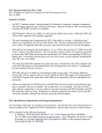
the motorized camera mount. On the backside of the enclosure, there is a charging port. Plug the male
end of the charging adapter into the port, and plug the other end into a standard 120Vac wall outlet.
Figure 2 shows this connection, and the subsequent charger required.
SATCOM-On-The-Move User Manual
Page 5 of 6
Charging Port
Figure 2: Charging Port Location and Required Charger
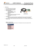
This 12Vdc battery should be able to provide the system with enough power for up to 5+ hours of
continuous use. The battery status is indicated on the front side of the enclosure in the “window.” Full
bars indicate that the system is fully charged, while less than 2 bars indicate the battery is nearly
depleted. Figure 2 shows the battery status indicator. A full re-charge of the battery requires 8 hours.
Figure 3: Battery Status Indicator
The second battery is within the camera and should be charged based upon the User Manual provided
from the camera manufacturer, Samsung (Model HFX90). It can simply be charged via standard USB to
Mini-USB cable. Plug the Mini-USB cable end into the camera, and the standard USB end into a +5V wall
charger.
SATCOM-On-The-Move User Manual
Page 6 of 6