1
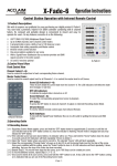
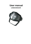
AL-Fade-6 II
Operation Instructions
Control Station Operation with Infrared Remote Control
1.Product Descriptions
We wish to express our gratitude for you purchasing our digital product AL-Fade-6 II. You now hold a premiere, hybrid 6-ch DMX
controller combining with 6 channel faders. Its compact and portable design is convenient to mount and easy to operate for users.
Its key features consist of as the following:
AL-Fade-6 II Kit
USITT DMX-512(1990) Multiplexed Digital Control
Up to 6 DMX channels and 6 channel control faders
6 programmable scenes, ability of up to 100 steps per scene
Assignable fadetime setting separately and Master control
One preset pattern available for per scene
Infrared remote control function
LED indicator on the panel to indicate the current operation
With a Junction BOX 1 as tension provider and DMX
signal converter in the entire system
US and EU versions optional
2.Control Panel View
Channel Faders(1~6):
Used to control the output level of each corresponding fixture channel.
Master Control Fader:
Used to control the overall output level for all Channels1~6 or control the master level
for all Scenes.
Scene Buttons(1~6):
To select the corresponding programmed scene to play back.
Scene LED indicators(1~6):
These 6 LEDs detail the current fader level for Scenes1-6. The LED indicators will reflect
the fader level changes in real time.
O/P Button:
To press the O/P button to close all channel1-6 output or enter/exit Recording Scene Mode.
O/P LED indicators:
To indicate the output state is turned on or off.
Infrared Sensor:
To receive infrared remote control signs from Infrared Remote.
RJ45 Interface:
To link with the Junction BOX 1 via C-LAN cable for getting the tension and DMX output.
AL-Fade-6 II
3.Technical Specifications
Power Requirement ........................................................................................... Junction Box 1
Connection ......................................................................................................... RJ 45 interface
IP Rating.............................................................................................................. IP 20
Control Protocol .................................................................................................. DMX-512 (1990)
Listing ................................................................................................................. CE certified
Operation temperature ........................................................................................ -10 degC to +50degC
Dimensions ......................................................................................................... US:120(L) x 76(W) x 15.5(H)mm
EU: 85(L) x 85(W) x 15.5(H)mm
Weights .............................................................................................................. 630g (EU) / 650g (US)(Full Packing)
Packing ............................................................................................................... 1 AL-Fade-6 II, 1 IR remote controller
1 Junction Box 1 & 1 User Manual
-Page 1-
4.Operating Guide
Online Operation
When dip-switch 10 is flipped to "ON" position, the online mode is enabled. Every
AL-Fade-6 II outputs the DMX data within 6 channels and the DMX address can
be set by flipping the dipswitches 1-9 inside the unit.
1 = ON
1 2 3 4 5 6 7 8 9 10
0= OFF
DMX is short for Digital Multiplex. This is a universal binary language used as a form of communication between intelligent fixtures. For
AL-Fade-6 II, the DMX address can be set by flipping the dipswitches 1-9 inside the unit and each Dip Switch represents a binary value.
1 = ON
1 2 3 4 5 6 7 8 9 10
SWITCHES ON
1
2
3
4
5
6
7
8
9
10
1
2
1,2
3
1,3
2,3
1,2,3
4
1,4
2,4
0= OFF
START
CH#
SWITCHES ON
11
12
13
14
15
1,2,4
3,4
1,3,4
2,3,4
1,2,3,4
511
.. .. .. ..
START
CH#
.. .. .. ..
Dip Switch 1 address equals 1
Dip Switch 2 address equals 2
Dip Switch 3 address equals 4
Dip Switch 4 address equals 8
Dip Switch 5 address equals 16
Dip Switch 6 address equals 32
Dip Switch 7 address equals 64
Dip Switch 8 address equals 128
Dip Switch 9 address equals 256
1,2,3,4,5,6,7,8,9
A DMX value(address) is set by combining the different dipswitches that will add up to the value you wish to achieve, for example:
Setting DMX address for 201.
Flip switches1,4,7,& 8 to the
"ON" position
1=1
4=8
Dipswitches# 7=64
Value
8=128
=201
*Note: The operation for the dipswitches will take effect only when repower the AL-Fade-6 II.
Setting DMX address for 21.
Flip switches1,3,&5 to the
"ON" position
1=1
3=4
Dipswitches# 5=16 Value
=21
Stand Alone Operation
When dip-switch 10 is flipped to "OFF" position, the Stand Alone mode is enabled.
Every AL-Fade-6 II outputs the DMX data of 512 channels.
1 = ON
0= OFF
4.1Recording Scenes
4.1.1 Recording Scenes Mode enables: press and hold down the "O/P" button for approximately 3 seconds until the LED indicator
next to the "O/P" button flashes with red. Now Record mode is engaged and you may release the "O/P" button.
4.1.2 If the selected scene has been stored before, its indicator will be on. Press and hold the "Scene" button down for about
2 seconds and all LED indicators will flash repeatedly 3 times to delete it.
4.1.3 Select the "Scene" button where you wish to record to. The selected "Scene" LED will flash repeatedly.
4.1.4 Adjust the corresponding "Channel Fader" all ways up to ten(10) to set the desired fader level for the step of the scene.
Once you're satisfied with the setting, press the "Scene" button to save it. All LED indicators will flash repeatedly 3 times,
indicating that the step of the scene has been recorded.
4.1.5 Repeat Step4.1.4 to record more steps for the scene, up to 100 Steps can be created per scene.
4.1.6 To record additional scenes, repeat Step4.1.3~4.1.5.
4.1.7 Once you've stored all of your scenes, press and hold the "O/P" button to exit. A blue LED next to the "O/P" button coming
on is indicative that you are out of the Recording Scene mode.
Note: If 2 continuous steps have the same data, they will merge into one step automatically. The fadetime now is two times
long as before merged.
In Online Mode, users can input external DMX data to create Scenes.
4.2 Assigning Scenes Fade time
4.2.1 Press and hold the "Scene" button to select the Scene where you wish to assign fade time to, until its indicator is flashing.
4.2.2 Keep on holding the selected "Scene" button, and adjust simultaneously the "Master control fader" all ways up to 600s to
set desired fader level.
4.2.3 Once you're satisfied with the setting, release the selected "Scene' button to save it. All LED indicators flash repeatedly
3 times.
4.2.4 To assign fade time for additional scenes, repeat Step4.2.1 through 4.2.3.
Note: Once you've saved fade time for all of your scenes, please move back the "Master Control Fader" to the initial position.
-Page 2-
4.3 Setting OFF Fade time
4.3.1 Recording Scene mode enables.
4.3.2 Adjust the "Master Control Fader" all ways up to 600s to set the desired level.
4.3.3 Once you're satisfied with the setting, tap the "O/P" button to save it. All LED indicators will flash repeatedly 3 times.
4.3.4 Exit the Recording Scene mode.
4.4 Setting the Total Number of Controllable Channels
4.4.1 Disconnect the main power of AL-Fade-6 II.
4.4.2 Select the channel total number which you wish to control. When using the "Channel Fader 1", the channel total which you wish
to control is "1"; when using the "Channel Fader 2", the channel total which you wish to control is "2", the rest can be deduced
and in the function, the channel total which you wish to control is up to "6".
4.4.3 Should adjust the "Master Control Fade" over 5 position when selecting the channel number.
4.4.4 Keep and hold the "O/P" button, and power on the AL-Fade-6 II, all LED indicators will come on. Release the "O/P" button, and all
LED indicators will flash repeatedly 3 times.
4.5 Playing back Scenes
4.5.1 Only the stored scenes can be played back.
4.5.2 Directly tap the "Scene" button to select the scene which you wish to play back.
4.5.3 Users can use the Infrared Remote to operate your AL-Fade-6 II.
4.6 Restoring Scenes
4.6.1 Power off the AL-Fade-6 II.
4.6.2 Keep and hold down the "Scene1" button which you wish to restore, and power on the main power of AL-Fade-6 II, until all
Scenes' LED indicators will illuminate. Then release the "Scene" button to restore, and all Scenes' LED indicators will flash
repeatedly 3 times
5.System Connection
L
N
IN
L
E
AC 120V~ 60Hz
N
POWER IN
E
THRU
CAUTION
Risk Of Electric Shock Disconnect Input Power
Before Opening
N'ouvrez Pas: risque De Choc Electrique
Warning: This Apparatus Must Be Earthed
J U N C T I O N B OX 1
DMX IN
DMX OUT
GND D- D+
GND D- D+
RoHS
Made in P.R.C.
Remote Control
1. DMX OUT +
2. DMX OUT 3. DMX IN +
4; 5. GND
6. DMX IN 7; 8. +12V
TO PANEL
DMX OUT
D+
GND
D-
CAT-5 data cable, 5 meters Max.
CAT-5 / RJ45 PIN CONNECTION
1. DMX OUT +
2. DMX OUT 3. DMX IN +
4. GND
5. GND
6. DMX IN 7. +12V
8. +12V
24-004-2772-00
Rev1.0
-Page 3-