1
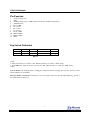
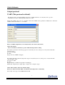
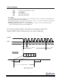
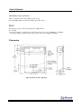
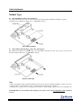
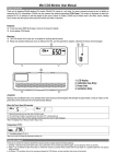
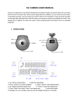
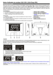
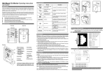
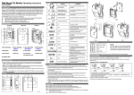
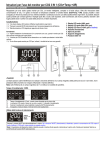
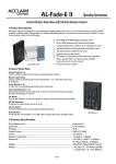
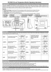
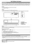
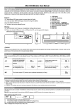
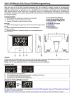
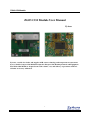
ZG03 CO2 Module
ZG03 CO2 Module User Manual
ZyAura
ZyAura, a world class leader and supplier of IR sensor technology and temperature measurement
devices Small, Compact CO2 Module Designed to Integrate Into Existing Controls and Equipment.
The ZG03 CO2 Module is designed to meet the volume, cost, and delivery expectations of HVAC.
All units are factory calibrated.
1
ZG03 CO2 Module
Contents
Features ...................................................................................................................................................3
Specification............................................................................................................................................3
Pin Function............................................................................................................................................4
Dip Switch Definition .............................................................................................................................4
Output protocol ......................................................................................................................................5
UART.......................................................................................................................................................5
DAC .........................................................................................................................................................7
Dimension................................................................................................................................................7
Module Type ...........................................................................................................................................8
2
ZG03 CO2 Module
Features
An affordable CO2 sensing solution for HVAC/DCV
Dual Beam NDIR
UART and DAC output
CO2, Temp output ( RH function ,optional )
Diffusion or Flow Through type is selectable
sNGC function Auto Calibration function
(
)
Specification
Method: Dual Beam NDIR (Non Dispersive Infrared)
Sampling method: Diffusion or Pumped Flow (50~200ml/min)
■Performance - CO2
Measurement Range
Accuracy
Repeatability
Temperature
Dependence
Pressure Dependence
Response Time
Warm-Up Time
0-3,000 ppm display (2000ppm, 5000ppm, 10,000ppm are optional)
±70 ppm or ±5% of reading
±20 ppm
Typ.±0.2% of reading per °C or ±2 ppm per °C, whichever is greater,
referenced to 25°C
0.13% of reading per mm Hg (Corrected via user input for altitude)
About 40sec for 90% of step change
<60 seconds
■ Performance - Temperature
32 to 122°F (0 to 50°C)
Temperature Range
±2°F (±1°C) When the fan blows to the device directly, the accuracy of
Accuracy
temperature is + / -1.5 °C.
20-30 minutes (case must equilibrate with environment)
Response Time
■ Performance – RH (Optional, default is null)
20%-90% RH
Measurement Range
Accuracy:
±5%RH@23°C
Response time:
About 5 min for 63% of step change
■ Operating Conditions
Operating conditions
Storage conditions
32°F to 122°F (0°C to 50°C)
0 to 95% RH, non condensing
-4°F to 140°F (-20°C to 60°C)
■Power Supply and Output
5VDC supply (+/-5%),Ripple and Noise (mVp-p) 200
Power Supply
Max.200mA, average :20mA
Power Consumption
0~4VDC (Temperature/RH ,CO2 are independent channel,
Analogue Output
RH and Temp. are the same channel , optional by Jumper)
-4°F to 140°F (-20°C to 60°C)
Storage conditions
Digital Output
UART(Baud Rate: 19200, Check Bit : None ,Data Bit: 8 bit, Stop Bit:1)
SPIr output (Special output )
3
ZG03 CO2 Module
Pin Function
1
5 VDC (input power)
2
GND
3
AVOUT (Temperature or RH, depends the Jumper, default is temperature)
4
AVOUT (CO2)
5
Data of SPIr
6
No connect
7
No connect
8
No connect
9
Clock of SPIr
10 TDX (UART)
11 RDX (UART)
12 GND
Dip Switch Definition
1
Na
Na
On
Off
2
UART
SPIr
3
sGNC Disable
sGNC Enable
4
RH
Temp
Table.1
1. NA
2. sNGC if the third code switch is ‘ON’, RH, if the third code switch is ‘OFF’, Temp.
3. Temp/RH: DAC output: when the code switch is ‘ON’, RH, when the code switch is ‘OFF’, Temp
4. NA
:
,
,
Note of sNGC After changing status of sNGC the machine should be restarted otherwise the outcome of CO2
will be influenced considerably.
:
,
Function enable of sNGC Please dial the second code switch to‘ON’ and open the sNGC Function otherwise
the sNGC Function will close.
4
ZG03 CO2 Module
Output protocol
UART (This protocol is default)
The digital output is standard UART; its baud rate is 19200, check bit: none. Data bit: 8 bit, stop bit: 1.
CO2 ItemCode is <P>, and Temperature ItemCode is <B>
Notes: The UART of this sensor is compatible with 3.3Vdc CMOS level specification. ZG03 need a “External
UART to RS232 transmitter” to connect PC.
There are 2kinds output mode, one is Master Mode; the other is Slave Mode.
Under Slave Mode:
User need send the command, to get the CO2 and temperature reading.
Read CO2 concentration: Read the gas ppm as measured by the sensor. Response is a2-byte Decimal value
giving the ppm.
Send: 23 31 30 0D
Possible
Reply: #1578 (for PPM =1578ppm)
Read Temp: Read the Ambient temperature degC as measured by the sensor. Response is a2-byte Decimal
value giving the degC.
Send: 23 31 31 0D
Possible
Reply: #2266 (for Ambient temperature =22.66degC)
Notes: The sample may be output degC or degF. Above sample is degC.
Under Master Mode: (that’s the default setting)
The device will send out the CO2 concentration and temperature continuously.
The format of message is: Item MSB LSB Sum CR
5
ZG03 CO2 Module
Item
MSB
LSB
Sum
CR
“B” (42h): Tobj (Temperature of Obj)
8 bit Data Msb
8 bit Data Lsb
Item+MSB+LSB=SUM
0Dh, end of the message
For example:
The CO2 ItemCode is “P”, If received message: 02 50 30 33 32 30 37 33 0D, that means P0320, CO2
concentration is Hex2Dec (0320) = 800ppm
The Temperature ItemCode is “B”,If received message: 02 42 31 32 38 30 44 34 0D, that means B1280,
Temperature is Hex2dec (1280)/16-273.15 = 22.85degC
The RH (optional ) ItemCode is “A”. if received message: 02 41 31 31 44 35 32 37 0D, that means
A11D5, the actual RH is Hex2Dec(11D5)/10000= 46%
Notes: The No.2 of Dip Switch must be “ON”. Otherwise the output protocol will be SPIr.
Timing of SPIr is below (This protocol is for factory calibration)
0
1
2
3
4
5
6
7
0
1
b1
b0
b7
CLOCK
DATA
b7
b6
b5
b4
b3
b2
b6
500us
Byte 0
Byte 1
Message format
Item MSB
LSB Sum
DATA
CR
DATA
20ms
Frame Interval
Fig1. Timing of SPI
6
ZG03 CO2 Module
SPIr Timing voltage specification:
,
,
SPIr is compatible with 3.3Vdc CMOS Data, Clock
Reset Pin ViH=2.0Vdc, ViL=0.8Vdc, VoH=2.4Vdc, VO = 0.8V
DAC
The analogue output of CO2 and temperature (or RH) is linear.
For example:
Aout (CO2) Output is 1.6V, that means CO2 concentration is 1.6(v)/4(v)*3000(ppm) = 1200ppm
Aout (Temp) Output is 2.0V, that means temperature is 2.0(v)/4(v)*50degC= 25.0degC
Dimension
Fig2. Board layout and component
7
ZG03 CO2 Module
Module Type
ZG03-D (Diffusion, this is the default type)
Air can be introduced to the sensor via the flow port and exit through the diffusion membrane (typical
configuration for calibration). Flow rate of ~100cc/Min required.
Fig.3 (Diffusion Filter)
ZG03-F(Flow Through Type,this is the optional type)
The diffusion membrane is replaced with a non permeable seal. The two flow ports can be used for flow
through sampling. Flow rate of ~100cc/Min required.
Fig4. Flow Through
Note:
)
)
(
,
1 Before using this module, the In-Line Filter must be fixed on the Air cell In-Line Filter is not the accessories
of the standards , ZyAura will not offer ,otherwise the dust will cause the deviation.
2 While power on the positive and negative pole must be connected right otherwise the sensor will burn out.
,
)
Warning:This ver. User manual is the temporary one; please refer to the www.ZyAura.com for updated
version.
8