1
K3635V3 9/04 Rev. A
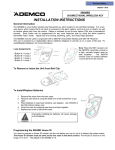
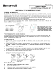
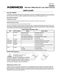
ADEMCO 5804BDV
TWO-WAY WIRELESS KEY WITH VOICE STATUS
INSTALLATION INSTRUCTIONS
General Information
To Install / Replace Batteries
The 5804BDV is a four-button wireless key that permits the
user to control the alarm system remotely. It is a two-way
device that can send a command to the alarm system, such
as to arm or disarm, as well as receive status back.
1.
2.
Status is indicated by two bi-color status LEDs and a
piezoelectric sounder. Each button can be programmed for
any zone response type, but is typically used for arming,
disarming, panic, and output relay operation.
1.
The 5804BDV must be used in conjunction with
one of the following:
•
5800TM (Transmitter Module) and a 5881or
5881EN receiver.
•
6128RF receiver.
•
Lynx control panel.
3.
4.
Remove the screw from the case back.
Remove case back by using the blade of a small
screwdriver to pry open.
Place batteries in case back locations (see diagram). Use
CR2430 or DL2430 Lithium battery only.
Close the case by snapping case front and back
together.
5. Replace the screw to secure the case.
!
WARNING!
Improperly installing the batteries will cause
damage to the batteries.
2. Place the 5881 or 5881EN receiver and the
5800TM Transmitter Module in a high, centrally
located area for best reception. The 5800TM
module must be located between 1 and 2 feet
from the receiver.
The unit is powered by 2 replaceable Lithium batteries
designed to provide up to 2 years of life. These batteries are
supplied with the unit but not installed (see “To Install/Replace
Batteries” for more information).
Red/Yellow
LED
Button B
Green/Yellow
LED
Button C
Programming the 5804BDV House ID
You must program a House ID number into the unit before
you can use it to display the system status. The House ID
number must be same as the one used in the alarm
control. The House ID must be in the range of 01 to 31. The
default in the 5804BDV is 10.
To Enter a House ID
Button A
5804BDV Front View
Belt Clip
5804BDV-001-V0
Button D
1.
2.
Loop Assignments:
• Button A =>Loop 3
• Button C =>Loop 4
• Button B =>Loop 2
• Button D =>Loop 1
3.
4.
Note:
To Remove or Insert the Unit from Belt Clip
5.
Enter House ID mode by pressing the “A,” “B,” and “C”
buttons at the same time until the Red and Green LEDs
alternate flashing.
Enter the House ID number by using the “A” button to
enter the 10’s digit and the “B” button to enter the 1’s
digit. Note: If the entry is out of range (greater than 31),
the unit will discard the entry.
Accept the entry by pressing the “D” button.
The unit displays the stored number by flashing the left
LED for the 10’s digit and flashing the right LED for the
1’s digit (for example, for House ID 21, the left LED will
flash twice, the right LED will flash once).
The unit will then exit the House ID mode.
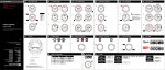
Example: To enter House ID # 17 into the unit:
2
3
4
5404BDV-002-V0
1
Enter HID mode:
Press A +B + C
buttons until LEDs
flash.
Enter HID #17: Press
& release A button
once, press & release
B button 7 times.
To accept entry,
press D button.
HID will be shown
by flashing LEDs.
Then exit HID mode.
5804BDV-004-V0
2. Answer Yes or No to the “Open/Close Report?” question.
3. Answer Yes to the “RF Button?” question.
4. Enter the zone number assigned to the Arm/Disarm
button. The keypad will show the summary of user
information on its display.
5. Test the Arm/Disarm button to make sure it operates
correctly.
To View the House ID
1. Enter House ID mode as described in step 1 (previous
page).
2. Depress the “D” button to view.
3. The unit will display the stored number as described in
step 4 (previous page). The unit will then exit House ID
mode.
Adjusting Volume Level
Programming a House ID in the Alarm
Control
•
•
This unit is shipped with the volume set to the lowest level. To
adjust the volume, proceed as follows:
1. Enter the Volume Level Programming mode by pressing
and holding the “A”, “B”, and “D” buttons simultaneously
until the unit’s red and green LEDs flash alternately.
Note that if no button is pressed for 5 seconds the unit
will automatically shut down and no change to the volume
level is made.
a. Press the “A” button for low volume level, or
b. Press the “B” button for medium volume level, or
c. Press the “C” button for maximum volume level. The
word “Alarm” will be heard at the volume level
selected.
2. Press the “D” to accept.
On VISTA-40, 50P, 100, and above, use Device
Programming mode to enable the RF receiver and enter
the House ID number.
On VIA-30PSE, VISTA-20SE, and below, go to field ✶24
and enter the House ID number.
Programming the Buttons
Each 5804BDV is assigned a unique serial number during
manufacture. Each button on the unit also has a unique
“loop” number that must be programmed into the alarm control
during installation. Assign each button to an individual zone
number and program the Input Type as “BR” (Button Type
RF) by entering “5” in the control’s Zone Programming mode.
Then, input the serial number by one of the following
methods:
•
Transmit twice from the device by pressing one of the
buttons when prompted for the serial number.
•
Enter the serial number manually through the keypad.
•
Enter the serial number through V-LINK or Compass
downloader software as applicable.
Be sure to include the loop number of each button during
programming (see loop assignments on previous page).
Volume level affects the life of the battery. Use low
volume for maximum battery life.
Operating the Buttons
To Activate a Function
To activate a programmed function, press and hold the
associated button down until the yellow LED flashes; then
release it.
To Request System Status
NOTE: Do not use the 5804BDV for 24-hour silent alarm, as
the unit itself is not silent.
Because the 5804BDV is a two-way device, users can check
the system status before arming or disarming their system. To
check system status, press and release any button
momentarily. The yellow LED will flash after you release the
button. After a second or two, the 5804BDV will display the
system status information using a combination of LED and
sounder activity (see the System Status Indications Table). If
5804BDV does not receive system status information from the
panel for approximately 5 seconds, it will shut itself down. It
will also shut itself down if there is no button activity within 5
seconds of receiving a status update.
Button C
If you choose not to use the “C” button, you must do the
following to avoid a “Check” condition when the button is
accidentally pressed:
1. Assign this button to a zone.
2. After the serial number has been programmed, re-enter
Zone Programming for that zone.
3.
At the “Zone Type” prompt, enter 00 and press [✶].
a) On VIA-30 controls and below, the system will ask
whether you want to permanently delete that zone.
Enter 0 (No). This will cause the system to retain the
serial number, but render the button inactive.
!
WARNING!
b) On VISTA-40 and above, continue to press [✶] until
you see the “Enter Zone No?” prompt again. At this
point, Press 00 and [✶]. Then press ✶99 to exit
Program mode.
On VISTA-40 and Above
If a button is assigned to zone type 20 (Arm Stay), 21 (Arm
Away), or 22 (Disarm), you must assign a user to the button in
order for it to operate.
To assign a user number to the Arm/Disarm button:
1. Enter [4-digit User Code] + 8 + [User No.] + [4-digit new
User Code].
–2–
This device may not receive the system
status properly if it operates within a few feet
of the 5881 RF receiver.
System Status Indications Table
LED
LED Condition
Red
On Steady
Speech
System Status
System Armed Away
Armed Away or Maximum
System Armed Stay
Armed Stay or Instant
Fire Fire Zone (Faulted Zone)
Fire Alarm in progress
Alarm Alarm Zone (Faulted Zone)
Armed, Burglary Alarm in progress
Alarm Alarm Zone (Faulted Zone)
Alarm Memory
On Steady
System Disarmed Ready To Arm
Disarmed, Ready to Arm
Flashing
System Disarmed Not Ready To Arm System Not Ready, Zones Faulted
Yellow (Right)
Flashing
––
Indicates RF transmission
Red & Green
Alternately
Flashing
––
In Enter House ID Mode
N/A
System AC Loss
AC Loss Condition
Low Battery
Low Battery Condition
Flashing
Green
N/A
In Set Volume Level Mode
Multiple Button Operations
!
Low-Battery Indication
The 5804BDV should not be used for 24-hour
silent alarm, as the unit itself is not silent.
WARNING!
Specifications
The 5804BDV can generate the same responses as keypad
panic key pairs of [✶] + [#] and [✶] + [1] by depressing “A” + “C”
and “B” + “D” button pairs, respectively.
You must depress the button pair for at least 2 seconds for the
5804BDV to recognize the button pair command. These button
pairs allow the user to activate panic, fire, and medical alarms
depending on control panel programming.
A + C Button Pair
When the unit goes into a low battery condition, the yellow
LED will not flash when a button is pressed. Change both
batteries immediately. Refer to instructions in “To
Install/Replace Batteries” paragraph on first page.
Physical:
Battery:
Belt Clip:
4.1H x 2.2”W x 0.8”D
Transmitter:
3.9”H x 2.0”W x 0.69”D
Maxell CR2430 or Duracell DL2430
B + D Button Pair
5804BDV-005-V0
FOR LIMITATIONS OF THE ENTIRE ALARM SYSTEM, REFER TO THE INSTALLATION INSTRUCTIONS FOR THE
CONTROL WITH WHICH THIS DEVICE IS USED.
FCC STATEMENT
This device complies with Part 15 of the FCC rules. Operation is subject to the following two conditions: (1)
This device may not cause harmful interference, and (2) This device must accept any interference received,
including interference that may cause undesired operation.
FCC ID.CFS8DL5804BDV
–3–
FEDERAL COMMUNICATIONS COMMISSION (FCC) Part 15 STATEMENT
This equipment has been tested to FCC requirements and has been found acceptable for use. The FCC requires the following statement
for your information:
This equipment generates and uses radio frequency energy and if not installed and used properly, that is, in strict accordance with the
manufacturer's instructions, may cause interference to radio and television reception. It has been type tested and found to comply with the
limits for a Class B computing device in accordance with the specifications in Part 15 of FCC Rules, which are designed to provide
reasonable protection against such interference in a residential installation. However, there is no guarantee that interference will not occur
in a particular installation. If this equipment does cause interference to radio or television reception, which can be determined by turning the
equipment off and on, the user is encouraged to try to correct the interference by one or more of the following measures:
•
If using an indoor antenna, have a quality outdoor antenna installed.
•
Reorient the receiving antenna until interference is reduced or eliminated.
•
Move the radio or television receiver away from the receiver/control.
•
Move the antenna leads away from any wire runs to the receiver/control.
•
Plug the receiver/control into a different outlet so that it and the radio or television receiver are on different branch circuits.
If necessary, the user should consult the dealer or an experienced radio/television technician for additional suggestions. The user or
installer may find the following booklet prepared by the Federal Communications Commission helpful: "Interference Handbook."
This booklet is available from the U.S. Government Printing Office, Washington, DC 20402.
The user shall not make any changes or modifications to the equipment unless authorized by the Installation Instructions or User's Manual.
Unauthorized changes or modifications could void the user's authority to operate the equipment.
LIMITED WARRANTY
Honeywell International Inc., acting through its Security & Custom Electronics business ("Seller") 165 Eileen Way, Syosset, New York 11791,
warrants its product(s) to be in conformance with its own plans and specifications and to be free from defects in materials and workmanship
under normal use and service for 24 months from the date stamp control on the product(s) or, for product(s) not having a manufacturer’s date
stamp, for 12 months from date of original purchase unless the installation instructions or catalog sets forth a shorter period, in which case the
shorter period shall apply. Seller's obligation shall be limited to repairing or replacing, at its option, free of charge for materials or labor, any
product(s) which is proved not in compliance with Seller's specifications or proves defective in materials or workmanship under normal use and
service. Seller shall have no obligation under this Limited Warranty or otherwise if the product(s) is altered or improperly repaired or serviced by
anyone other than Honeywell factory service. Connection of any device(s) to a communicating bus of a Honeywell security system (e.g., keypad
bus, polling loop) other than those manufactured or approved by Honeywell shall void this warranty. For warranty service, return product(s)
transportation prepaid, to Honeywell Factory Service, 165 Eileen Way, Syosset, New York 11791.
THERE ARE NO WARRANTIES, EXPRESS OR IMPLIED, OF MERCHANTABILITY, OR FITNESS FOR A PARTICULAR PURPOSE OR
OTHERWISE, WHICH EXTEND BEYOND THE DESCRIPTION ON THE FACE HEREOF. IN NO CASE SHALL SELLER BE LIABLE TO
ANYONE FOR ANY CONSEQUENTIAL OR INCIDENTAL DAMAGES FOR BREACH OF THIS OR ANY OTHER WARRANTY, EXPRESS OR
IMPLIED, OR UPON ANY OTHER BASIS OF LIABILITY WHATSOEVER, EVEN IF THE LOSS OR DAMAGE IS CAUSED BY THE SELLER'S
OWN NEGLIGENCE OR FAULT.
Seller does not represent that the product(s) it sells may not be compromised or circumvented; that the product(s) will prevent any personal
injury or property loss by burglary, robbery, fire or otherwise; or that the product(s) will in all cases provide adequate warning or protection.
Customer understands that a properly installed and maintained alarm system may only reduce the risk of a burglary, robbery, fire, or other
events occurring without providing an alarm, but it is not insurance or a guarantee that such will not occur or that there will be no personal injury
or property loss as a result. CONSEQUENTLY, SELLER SHALL HAVE NO LIABILITY FOR ANY PERSONAL INJURY, PROPERTY DAMAGE
OR OTHER LOSS BASED ON A CLAIM THAT THE PRODUCT(S) FAILED TO GIVE WARNING. HOWEVER, IF SELLER IS HELD LIABLE,
WHETHER DIRECTLY OR INDIRECTLY, FOR ANY LOSS OR DAMAGE ARISING UNDER THIS LIMITED WARRANTY OR OTHERWISE,
REGARDLESS OF CAUSE OR ORIGIN, SELLER'S MAXIMUM LIABILITY SHALL NOT IN ANY CASE EXCEED THE PURCHASE PRICE OF
THE PRODUCT(S), WHICH SHALL BE THE COMPLETE AND EXCLUSIVE REMEDY AGAINST SELLER.
This warranty replaces any previous warranties and is the only warranty made by Seller on this product(s). No increase or alteration, written or
verbal, of the obligations of this Limited Warranty is authorized.
165 Eileen Way, Syosset, New York 11791
Copyright © 2004 Honeywell International Inc.
www.honeywell.com/security
ÊK3635V3aŠ
K3635V3 9/04 Rev. A