1
Turbo-V 3K-T Pumping
System
Models
969-8875, 969-8877, 969-8879, 969-8881,
969-8882, 969-8883, 969-8884, 969-8885
Manuale di istruzioni
Bedienungshandbuch
Notice de mode d’emploi
Manual de istrucciones
Manual de istruções
Bedrijfshandleiding
Istrukstionsbog
Bruksanvisning
87-900-979-01 (F)
04/2011
Instruksjon manual
Ohjekäsikirja
Felhasználói kézikönyv
Podrecznik instrukcji
Návod k použití
Návod na obsluhu
Priročnik za navodila
User Manual
Notices
© Agilent Technologies, Inc. 2011
No part of this manual may be
reproduced in any form or by any
means (including electronic storage
and retrieval or translation into a
foreign language) without prior
agreement and written consent from
Agilent Technologies, Inc. as governed
by United States and international
copyright laws.
Manual Part Number
Publication Number: 87-900-979-01 (F)
Edition
Edition 04/2011
Printed in ITALY
Agilent Technologies Italia S.p.A.
Vacuum Products Division
Via F.lli Varian, 54
10040 Leinì (TO)
ITALY
Warranty
The material contained in this
document is provided “as is,” and is
subject to being changed, without
notice, in future editions. Further, to
the maximum extent permitted by
applicable law, Agilent disclaims all
warranties, either express or implied,
with regard to this manual and any
information contained herein,
including but not limited to the
implied warranties of merchantability
and fitness for a particular purpose.
Agilent shall not be liable for errors
or for incidental or consequential
damages in connection with the
furnishing, use, or performance of
this document or of any information
contained herein. Should Agilent and
the user have a separate written
agreement with warranty terms
covering the material in this
document that conflict with these
terms, the warranty terms in the
separate agreement shall control.
Technology Licenses
The hardware and/or software
described in this document are
furnished under a license and may be
used or copied only in accordance
with the terms of such license.
Restricted Rights Legend
If software is for use in the
performance of a U.S. Government
prime contract or subcontract,
Software is delivered and licensed as
“Commercial computer software” as
defined in DFAR 252.227-7014 (June
1995), or as a “commercial item” as
defined in FAR 2.101(a) or as
“Restricted computer software” as
defined in FAR 52.227-19 (June 1987)
or any equivalent agency regulation or
contract clause. Use, duplication or
disclosure of Software is subject to
Agilent Technologies’ standard
commercial license terms, and nonDOD Departments and Agencies of the
U.S. Government will receive no
greater than Restricted Rights as
defined in FAR 52.227-19(c)(1-2) (June
1987). U.S. Government users will
receive no greater than Limited Rights
as defined in FAR 52.227-14 (June
1987) or DFAR 252.227-7015 (b)(2)
(November 1995), as applicable in any
technical data.
Trademarks
Windows and MS Windows are U.S.
registered trademarks of Microsoft
Corporation.
Safety Notices
CAUTION
A CAUTION notice denotes a hazard.
It calls attention to an operating
procedure, practice, or the like that, if
not correctly performed or adhered to,
could result in damage to the product
or loss of important data. Do not
proceed beyond a CAUTION notice
until the indicated conditions are fully
understood and met.
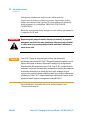
WARNING
A WARNING notice denotes a
hazard. It calls attention to an
operating procedure, practice, or the
like that, if not correctly performed
or adhered to, could result in
personal injury or death. Do not
proceed beyond a WARNING notice
until the indicated conditions are
fully understood and met.
Turbo-V 3K-T Pumping System User Manual / 87-900-979-01 (F)
Turbo-V 3K-T
Turbo-V 3K-T
Turbo-V 3K-T Pumping System User Manual / 87-900-979-01 (F)
3/388
Turbo-V 3K-T
4/388
Turbo-V 3K-T Pumping System User Manual / 87-900-979-01 (F)
Contents
Contents
1
Istruzioni per l’uso 13 Indicazioni di Sicurezza per Pompe Turbomolecolari
Informazioni Generali
14 15 Immagazzinamento 17 Preparazione per l’installazione 18 Installazione
20 Uso 23 Manutenzione 28 Smaltimento
2
29 Gebrauchsanleitung 31 Sicherheitshinweise für Turbomolekularpumpen 32 Allgemeine Informationen
Lagerung
33 35 Vor der Installation 36 Installation 38 Gebrauch
41 Wartung
46 Entsorgung 47 Turbo-V 3K-T Pumping System User Manual / 87-900-979-01 (F)
5/388
Contents
3
Mode d’emploi
49 Normes de sécurité pour Pompe Turbomoléculaires
Indications generales
Stockage
50 51 53 Preparation pour l‘installation
54 Installation 56 Utilisation 59 Entretien
64 Mise au rebut
4
65 Manual de istrucciones 67 Indicaciones de Seguridad para Bombas Turbomoleculares
68 Información general 69 Almacenamiento
71 Preparación para la instalación
72 Instalación 74 Uso 77 Mantenimiento 82 Eliminación 83 5
Manual de Istruções
85 Indicações de Segurança para Bombas Turbomoleculares 86 Informações gerais 87 Armazenagem 89 6/388
Turbo-V 3K-T Pumping System User Manual / 87-900-979-01 (F)
Contents
Preparação para a instalação 90 Instalação 92 Utilização
95 Manutenção
100 Eliminação 101 6
Bedrijfshandleiding 103 Veiligheidsinstructies voor Turbomoleculaire pompen 104 Algemene informatie
Opslag
107 Uitpakken
108 Installatie
110 Gebruik
113 105 Onderhoud 118 Afvalverwerking 119 7
Istruktionsbog
121 Sikkerhedsanvisninger for Molekylære turbopumper
122 Generel Information 123 Opbevaring 125 Forberedelse før installation 126 Installation 128 Anvendelse 131 Vedligeholdelse 136 Turbo-V 3K-T Pumping System User Manual / 87-900-979-01 (F)
7/388
Contents
Bortskaffelse
8
137 Bruksanvisning
139 Säkerhetsanvisningar för Molekylära turbopumpar 140 Allmän Information 141 Förvaring
143 Förberedelser för installationen 144 Installation 146 Användning 149 Underhåll
154 Bortskaffning
9
155 Instruksjon Manual 157 Sikkerhetsanvisninger for Turbomolekylære pumper
158 Generell informasjon 159 Lagring
161 Klargjøre til installasjon 162 Installasjon 164 Bruk
167 Vedlikehold 172 Eliminering 173 10 Ohjekäsikirja
175 Turbomolekyylipumppujen Turvaohjeet
Yleisiä tietoja
8/388
176 177 Turbo-V 3K-T Pumping System User Manual / 87-900-979-01 (F)
Contents
Varastointi 179 Valmistelut asennusta varten180 Asennus
182 Käyttö
185 Huolto
190 Hävittäminen
191 11 Felhasználói Kézikönyv 193 Biztonsági útmutató Turbómolekuláris szivattyúkhoz 194 Általános információk
Tárolás
195 197 Előkészítés telepítésre
Telepítés
200 Használat
203 Karbantartás
198 208 Megsemmisítés 209 12 Podrecznik Instrukcji
211 Wskazówki dotyczące bezpieczeństwa dla Pomp
Turbomolekularnych 212 Ogólne informacje
213 Magazynowanie 215 Przygotowanie do instalacji 216 Instalacja
218 Użytkowanie
221 Turbo-V 3K-T Pumping System User Manual / 87-900-979-01 (F)
9/388
Contents
Konserwacja
226 Przetworstwo odpadow 227 13 Návod k Použití
229 Bezpečnostní návod pro Turbomolekulární vývěvy 230 Všeobecné informace
231 Uskladnění 233 Příprava k instalaci 234 Instalace
236 Použití
239 Údržba
244 Likvidace
245 14 Návod na Obsluhu 247 Bezpečnostné návod pre Turbomolekulárne vývevy
Všeobecné informácie
Uchovávanie
254 Použitie
257 Údržba
262 Likvidácia
263 249 251 Príprava na inštaláciu
Inštalácia
248 15 Priročnik za Navodila
252 265 Varnostna navodila za Turbomolekularne črpalke 266 10/388
Turbo-V 3K-T Pumping System User Manual / 87-900-979-01 (F)
Contents
Splošne informacije 267 Shranjevanje
269 Priprava za montažo 270 Montaža
272 Uporaba
275 Vzdrževanje 280 Odlaganje opadkov 281 16 Instructions for Use 283 Safety Guideline for Turbomolecular Pumps
284 General Information 285 Storage
287 Preparation for Installation 288 Installation 290 Use 293 Maintenance
Disposal
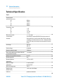
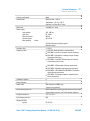
298 299 17 Technical Information
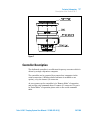
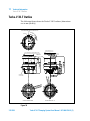
301 Description of the Turbo-V 3K-T 303 Technical Specification 308 Turbo-V 3K-T Outline
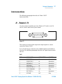
Interconnections
312 313 Serial Cable Installation 325 Turbo-V 3K-T Pumping System User Manual / 87-900-979-01 (F)
11/388
Contents
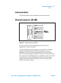
RS 232/RS 485 communication description
Monitorr
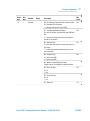
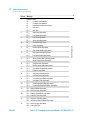
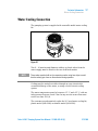
325 337 Profibus option 352 Profibus Message Mapping 358 Inlet Screen Installation 370 Water Cooling Connection
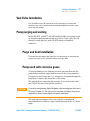
373 Vent Valve Installation 375 Pump purging and venting
375 High Vacuum Flange Connection 378 Fore-Vacuum Pump Connection 380 Pump Used in Presence of Magnetic Fields
380 Orderable Parts 381 12/388
Turbo-V 3K-T Pumping System User Manual / 87-900-979-01 (F)
Turbo-V 3K-T Pumping System User Manual
1
Istruzioni per l’uso
Indicazioni di Sicurezza per Pompe Turbomolecolari
Informazioni Generali 15
Immagazzinamento 17
Preparazione per l’installazione 18
Installazione
20
Uso 23
Uso della Turbo-V 3K- 24
Come avviare il sistema 24
Come arrestare la Turbo-V 3K-T 27
Arresto di Emergenza 27
Manutenzione
28
Smaltimento
29
14
Traduzione delle istruzioni originali
13/388
1
Istruzioni per l’uso
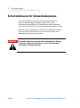
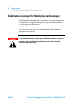
Indicazioni di Sicurezza per Pompe Turbomolecolari
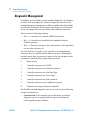
Indicazioni di Sicurezza per Pompe Turbomolecolari
Le pompe Turbomolecolari descritte nel seguente Manuale di
Istruzioni hanno una elevata quantità di energia cinetica dovuta alla
alta velocità di rotazione in unione alla massa specifica dei loro
rotori.
Nel caso di un guasto del sistema, ad esempio per un contatto tra
rotore e statore o per una rottura del rotore, l'energia di rotazione
potrebbe essere rilasciata.
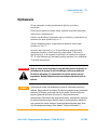
AVVERTENZA! Per evitare danni all'apparecchiatura e prevenire lesioni agli operatori, è
necessario seguire attentamente le istruzioni di installazione descritte nel
presente manuale!
14/388
Turbo-V 3K-T Pumping System User Manual / 87-900-979-01 (F)
Istruzioni per l’uso
Informazioni Generali
1
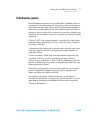
Informazioni Generali
Questa apparecchiatura è destinata ad uso professionale.
L'utilizzatore deve leggere attentamente il presente manuale di
istruzioni ed ogni altra informazione addizionale fornita dalla Agilent
prima dell'utilizzo dell'apparecchiatura. La Agilent si ritiene sollevata
da eventuali responsabilità dovute all'inosservanza totale o parziale
delle istruzioni, ad uso improprio da parte di personale non
addestrato, ad interventi non autorizzati o ad uso contrario alle
normative nazionali specifiche.
La Turbo-V 3K-T è un sistema integrato costituito da una pompa
turbomolecolare per applicazioni di alto e ultra alto vuoto e dal
relativo controller. Il sistema è capace di pompare molti tipi di gas o
di composto gassoso, ma non è adatto per il pompaggio di liquidi o di
particelle solide.
L'effetto pompante è ottenuto tramite una turbina rotante ad elevata
velocità (31800 giri/min. max) mossa da un motore elettrico trifase
ad alto rendimento. La Turbo-V 3K-T è totalmente priva di agenti
contaminanti, ed è quindi adatta per applicazioni che richiedono un
vuoto "pulito".
Ha inoltre dei connettori ausiliari tramite i quali è possibile pilotarlo
da remoto tramite un computer host collegato con linea seriale
(RS232 o RS485).
Nei paragrafi seguenti sono riportate tutte le informazioni necessarie
a garantire la sicurezza dell'operatore durante l'utilizzo
dell'apparecchiatura. Informazioni dettagliate sono fornite
nell'appendice “Technical Information”.
Turbo-V 3K-T Pumping System User Manual / 87-900-979-01 (F)
15/388
1
Istruzioni per l’uso
Informazioni Generali
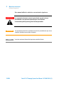
Questo manuale utilizza le seguenti convenzioni:
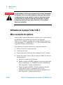
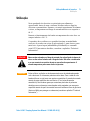
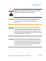
AVVERTENZA! I messaggi di avvertenza attirano l’attenzione dell’operatore su una
procedura o una pratica specifica che, se non eseguita in modo corretto,
potrebbe provocare gravi lesioni personali.
ATTENZIONE! I messaggi di attenzione sono visualizzati prima di procedure che, se non
osservate, potrebbero causare danni all’apparecchiatura.
NOTA
16/388
Le note contengono informazioni importanti estrapolate dal testo.
Turbo-V 3K-T Pumping System User Manual / 87-900-979-01 (F)
Istruzioni per l’uso
Immagazzinamento
1
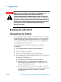
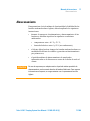
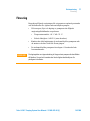
Immagazzinamento
Per garantire il massimo livello di funzionalità ed affidabilità delle
pompe Turbomolecolari Agilent, devono essere osservate le seguenti
prescrizioni:
durante il trasporto, lo spostamento e l'immagazzinamento delle
pompe non devono essere superate le seguenti condizioni
ambientali:
temperatura: da –20 °C a 70 °C
umidità relativa: da 0 a 95 % (non condensante)
il cliente deve sempre avviare le pompe turbomolecolari nel modo
Soft-Start quando ricevute e messe in funzione per la prima volta
il tempo di immagazzinamento di una pompa turbomolecolare è
di 10 mesi dalla data di spedizione.
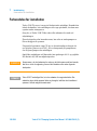
ATTENZIONE! Se, per qualsiasi ragione, il tempo di immagazzinamento è superiore, occorre
reinviare la pompa in fabbrica. Per ogni informazione, si prega di contattare il
locale rappresentante della Agilent.
Turbo-V 3K-T Pumping System User Manual / 87-900-979-01 (F)
17/388
1
Istruzioni per l’uso
Preparazione per l’installazione
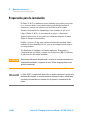
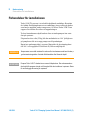
Preparazione per l’installazione
La Turbo-V 3K-T viene fornita in un imballo protettivo speciale; se si
presentano segni di danni, che potrebbero essersi verificati durante il
trasporto, contattare l'ufficio vendite locale.
Durante l'operazione di disimballaggio, prestare particolare
attenzione a non lasciar cadere la Turbo-V 3K-T e a non sottoporla ad
urti o vibrazioni.
Rimuovere la protezione dei connettori solo dopo che la turbopompa
è stata fissata al sistema.
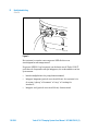
A causa del suo peso (55 kg) per estrarre la pompa dall'imballo
utilizzare i tre golfari a 120° avvitati sul corpo pompa.
Non disperdere l'imballo nell'ambiente. Il materiale è completamente
riciclabile e risponde alla direttiva CEE 85/399 per la tutela
dell'ambiente.
ATTENZIONE! Onde evitare problemi di degasamento, non toccare con le mani nude i
componenti destinati ad essere esposti al vuoto. Utilizzare sempre i guanti o altra
protezione adeguata.
NOTA
18/388
La Turbo-V 3K-T non può essere danneggiata rimanendo semplicemente esposta
all'atmosfera. Si consiglia comunque di mantenere la pompa chiusa e sigillata
fino al momento dell'installazione sul sistema. Questo per prevenire la
contaminazione del sistema.
Turbo-V 3K-T Pumping System User Manual / 87-900-979-01 (F)
Istruzioni per l’uso
Preparazione per l’installazione
1
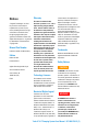
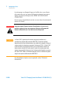
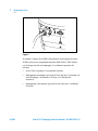
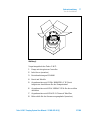
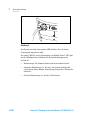
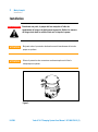
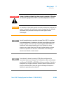
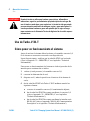
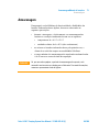
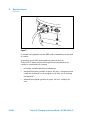
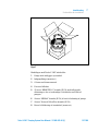
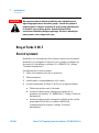
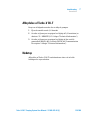
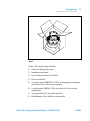
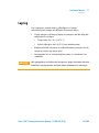
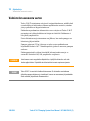
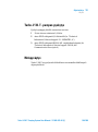
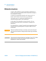
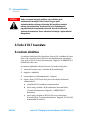
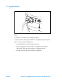
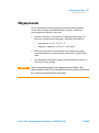
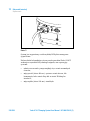
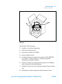
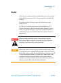
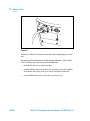
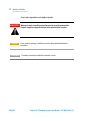
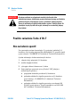
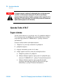
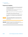
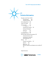
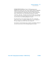
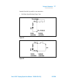
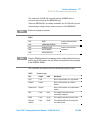
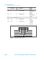
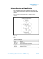
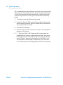
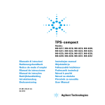
Figura 1
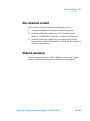
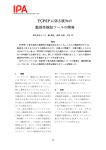
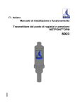
Nell’imballo della Turbo-V 3K-T sono compresi:
1
pompa con controller integrato
2
inlet screen (montato)
3
questo manuale su CD-ROM
4
sacchetto accessori
5
controconnettore a 15 vie “REMOTE I/O” IP-54 con integrate le
connessioni necessarie a far partire la pompa
6
controconnettore a 9 vie “SERIAL” IP-54 da utilizzare per la
connessione seriale
7
controconnettore a 9 pin IP-54 per il "Network" MoniTorr
8
staffetta per la ritenzione del cavo di alimentazione (montata).
Turbo-V 3K-T Pumping System User Manual / 87-900-979-01 (F)
19/388
1
Istruzioni per l’uso
Installazione
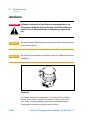
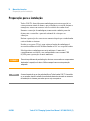
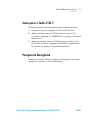
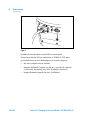
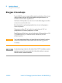
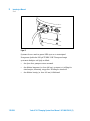
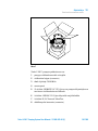
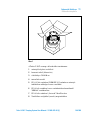
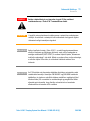
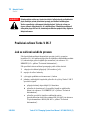
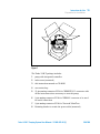
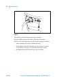
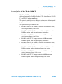
Installazione
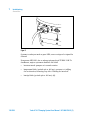
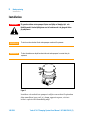
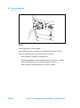
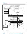
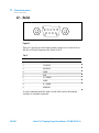
AVVERTENZA! La pompa, a causa del suo peso, deve essere maneggiata tramite appositi
attrezzi di sollevamento e spostamento. All’uopo utilizzare gli appositi golfari
avvitati nei fori filettati praticati sul corpo pompa.
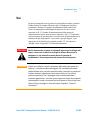
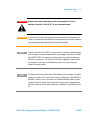
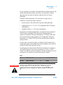
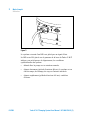
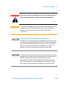
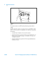
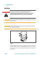
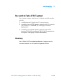
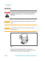
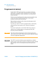
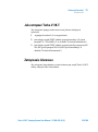
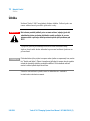
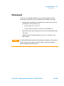
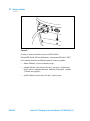
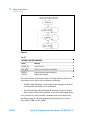
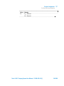
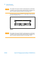
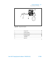
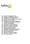
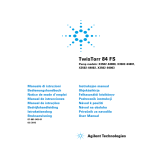
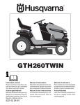
ATTENZIONE! Non rimuovere la copertura imbullonata prima del collegamento della
turbopompa al sistema.
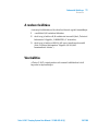
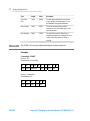
ATTENZIONE! Rimuovere la protezione dei connettori solo dopo che la turbopompa è stata
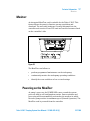
WARNING
fissata al sistema.
NO
YES
CH
AM
BER
RE
MO
VE
ME
THIS
CH
AN
PR
ICA
L INS OTEC
TAL TION
LAT
ION AFTER
Figura 2
Non installare e/o utilizzare la pompa in ambienti esposti ad agenti
atmosferici (pioggia, gelo, neve), polveri, gas aggressivi, in ambienti
esplosivi o con elevato rischio di incendio.
20/388
Turbo-V 3K-T Pumping System User Manual / 87-900-979-01 (F)
Istruzioni per l’uso
Installazione
1
Durante il funzionamento è necessario che siano rispettate le
seguenti condizioni ambientali:
pressione massima: 2 bar oltre la pressione atmosferica
temperatura dell'aria: da + 5 °C a +40 °C
umidità relativa: 0 – 95 % (non condensante).
In presenza di campi elettromagnetici la pompa deve essere protetta
tramite opportuni schermi. Vedere l'appendice "Technical
Information" per ulteriori dettagli.
La Turbo-V 3K-T deve essere collegata ad una pompa primaria
(vedere schema in "Technical Information").
La Turbo-V 3K-T può essere installata in qualsiasi posizione. Fissare
la Turbo-V 3K-T in posizione stabile collegando la flangia di ingresso
della turbopompa ad una controflangia fissa capace di resistere ad
una coppia di 43000 Nm attorno al proprio asse.
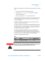
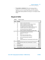
La turbopompa con flangia di ingresso ISO F deve essere fissata alla
camera da vuoto per mezzo di bulloni con una classe di fissaggio di
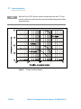
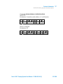
12.9 (σr = 1200 N/mm2). La seguente tabella descrive il numero di
bulloni d’acciaio necessari e con quale coppia di serraggio consigliata
da Agilent stringerli.
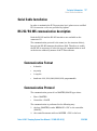
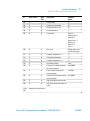
Tab. 1
FLANGIA
TIPO DI FISSAGGIO
N.
COPPIA DI SERRAGGIO
ISO 250 F
Bullone con filettatura M10
12
40 Nm
AVVERTENZA! La Turbo-V 3K-T non può essere fissata tramite la sua base. Il sistema può
essere fissato solo tramite la sua flangia ISO 250F o CFF 12".
Turbo-V 3K-T Pumping System User Manual / 87-900-979-01 (F)
21/388
1
Istruzioni per l’uso
Installazione
La turbopompa con flangia di ingresso ConFlat deve essere fissata
alla camera da vuoto per mezzo dell'apposita minuteria meccanica
Agilent. Per ulteriori dettagli vedere "HIGH VACUUM FLANGE
CONNECTION".
Devono essere usati bulloni in acciaio con una classe di resistenza di
almeno 500 N/mm2.
AVVERTENZA! Il mancato rispetto di queste istruzioni d’installazione, nel caso in cui si
verifichi un guasto al rotore, può comportare il distacco della pompa dal
sistema con danni alle cose o seri danni o morte delle persone.
ATTENZIONE! La Turbo-V 3K-T appartiene alla seconda categoria di installazione (o
sovratensione) prevista dalla normativa EN 61010-1. Connettere quindi il
dispositivo ad una linea di alimentazione che soddisfi tale categoria. Utilizzare i
controconnettori in dotazione per garantire l'isolamento IP-54. La Turbo-V 3K-T
ha dei connettori per gli ingressi/uscite e per la comunicazione seriale che
devono essere connessi ai circuiti esterni in modo che nessuna parte sotto
tensione sia accessibile. Assicurarsi che l’isolamento del dispositivo connesso
alla Turbo-V 3K-T abbia un isolamento adeguato anche in condizione di guasto
singolo come previsto dalla normativa EN 61010-1.
Per l'installazione degli accessori opzionali, vedere "Technical
Information".
22/388
Turbo-V 3K-T Pumping System User Manual / 87-900-979-01 (F)
Istruzioni per l’uso
Uso
1
Uso
In questo paragrafo sono riportate le principali procedure operative.
Prima di usare il sistema effettuare tutti i collegamenti elettrici e
pneumatici. Durante l'eventuale riscaldamento della camera da
vuoto, la temperatura sulla flangia di ingresso non deve essere
superiore a 80 °C. Durante il funzionamento della pompa la
temperatura del rotore non deve mai superare i 120 °C. L'operatore
deve assicurarsi di predisporre il corretto modo di funzionamento in
funzione del gas da pompare: 1 per Azoto e gas più leggeri, 0 per
Argon (modo di default) nel comando seriale 157. Per ulteriori
dettagli vedere l'appendice "Technical Information".
AVVERTENZA! Non far funzionare mai la pompa se la flangia di ingresso non è collegata alla
camera a vuoto o non è chiusa con la flangia di chiusura. Non toccare la
turbopompa e i suoi eventuali accessori durante le operazioni di
riscaldamento. L'elevata temperatura può causare lesioni alle persone.
ATTENZIONE! Evitare urti, oscillazioni o bruschi spostamenti della turbopompa quando è in
funzione. I cuscinetti potrebbero danneggiarsi. Per la mandata all'aria della
pompa utilizzare aria o gas inerte esente da polvere o particelle. La pressione di
ingresso attraverso l'apposita porta deve essere inferiore a 1 bar (oltre la
pressione atmosferica). Per il pompaggio di gas contenenti particolato o
inquinanti aggressivi per i cuscinetti, queste pompe sono dotate di una apposita
porta attraverso la quale è necessario fornire alla pompa un flusso di gas inerte
(Azoto o Elio) per proteggere i cuscinetti (vedere l'appendice "Technical
Information").
Turbo-V 3K-T Pumping System User Manual / 87-900-979-01 (F)
23/388
1
Istruzioni per l’uso
Uso
AVVERTENZA! Quando la pompa viene utilizzata per il pompaggio di gas tossici, infiammabili
o radioattivi, seguire le appropriate procedure tipiche di ciascun gas. Non
usare la pompa in presenza di gas esplosivi. La pompa è progettata per avere
un alto trasferimento di Azoto, Argon e gas più leggeri. Nel caso in cui ci
fosse la necessità di pompare gas più pesanti dell'Argon si prega di prendere
contatti con l'Assistenza Tecnica della Agilent per informazioni.
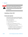
Uso della Turbo-V 3K-T
Come avviare il sistema
Prima dell'avvio del sistema, controllare che il controconnettore I/O
sia rimosso. Se il sistema è collegato ad un dispositivo di
Inpu/Output remoto, assicurarsi che il segnale di STOP sia attivo
(vedere il paragrafo "J1 – REMOTE I/O" nell'appendice "Technical
Information").
Per avviare il sistema eseguire i seguenti passi:
24/388
1
rimuovere (se presente) il controconnettore I/O
2
collegare l'alimentazione di rete
3
portare la pressione all'interno della camera a vuoto a 0,1 mbar
4
fornire alla Turbo-V 3K-T il segnale di START in uno dei seguenti
modi:
a
collegare il controconnettore I/O in dotazione
b
dare il segnale di START da remoto tramite il connettore I/O
(vedere il paragrafo "J1 – REMOTE I/O" nell'appendice
"Technical Information")
c
dare il segnale di START da remoto tramite l'interfaccia
seriale RS 232/485 (vedere il paragrafo "RS 232/485
Communication Description" nell'appendice "Technical
Information").
Turbo-V 3K-T Pumping System User Manual / 87-900-979-01 (F)
Istruzioni per l’uso
Uso
1
AVVERTENZA! Quando viene fornita l'alimentazione ed il controconnettore a 15 pin in
dotazione è inserito, la Turbo-V 3K-T si avvia automaticamente.
ATTENZIONE! Il controller viene fornito già connesso meccanicamente ed elettricamente alla
pompa. La separazione del controller dal corpo pompa può solo essere effettuata
da personale autorizzato dalla Agilent Vacuum Technologies.
NOTA
Quando si avvia la Turbo-V 3K-T per la prima volta, il controller automaticamente
avvia il sistema con una procedura speciale che protegge i cuscinetti da possibili
danni (SOFT START). Il sistema viene avviato a passi successivi fino alla piena
velocità in un tempo di 1 ora. Dopo che il sistema ha raggiunto la piena velocità,
la procedura di "soft start" viene disabilitata e gli avvii successivi vengono
eseguiti nel modo normale.
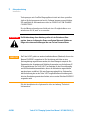
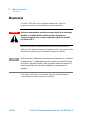
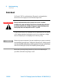
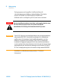
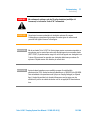
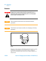
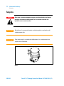
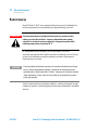
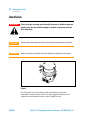
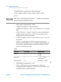
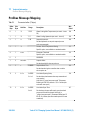
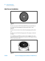
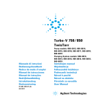
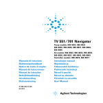
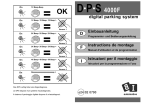
NOTA
Per mantenere il livello di protezione IP-54 utilizzare esclusi-vamente i connettori
forniti con la pompa. Per il cavo di alimen-tazione utilizzare solo i PN: 969-9957 o
969-9958, e fissare il cavo al controller con l’apposita staffetta (vedere la figura
seguente). Utilizzare questo cavo e spina insieme ad una presa adeguatamente
connessa a terra per evitare scosse elettriche e soddisfare i requisiti delle norme
CE.
Turbo-V 3K-T Pumping System User Manual / 87-900-979-01 (F)
25/388
1
Istruzioni per l’uso
Uso
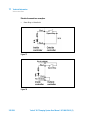
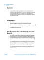
Figura 3
Il sistema è fornito di un LED verde pilotato da un segnale di stato.
Il LED verde posto sul pannello frontale della Turbo-V 3K-T indica,
con la frequenza del suo lampeggio, le condizioni operative del
sistema:
26/388
acceso fisso: la pompa è in rotazione normale;
lampeggiante lentamente (periodo di circa 400 ms): il sistema è in
stato di rampa, o di frenata, o di Stop, o di “Waiting for
interlock”;
lampeggiante velocemente (periodo di circa 200 ms): condizione
di errore.
Turbo-V 3K-T Pumping System User Manual / 87-900-979-01 (F)
Istruzioni per l’uso
Uso
1
Come arrestare la Turbo-V 3K-T
Per arrestare la pompa si può usare uno dei seguenti metodi:
1
togliendo il controconnettore di I/O in dotazione
2
inviando un segnale di STOP da remoto tramite il connettore I/O
(vedere il paragrafo "J1 – REMOTE I/O" nell'appendice "Technical
Information")
3
inviando un segnale di STOP da remoto tramite l'interfaccia
seriale RS 232/485 (vedere il paragrafo "RS 232/485
Communication Description" nell'appendice "Technical
Information").
Arresto di Emergenza
Per arrestare immediatamente in condizioni di emergenza la Turbo-V
3K-T occorre staccare il cavo di alimentazione dall'alimentazione.
Turbo-V 3K-T Pumping System User Manual / 87-900-979-01 (F)
27/388
1
Istruzioni per l’uso
Manutenzione
Manutenzione
La Turbo-V 3K-T non richiede alcuna manutenzione. Qualsiasi
intervento deve essere eseguito da personale autorizzato.
AVVERTENZA! Prima di effettuare qualsiasi intervento sul sistema scollegarlo
dall’alimentazione, mandare all'aria la pompa aprendo l'apposita
elettrovalvola, attendere fino al completo arresto del rotore ed attendere che
la temperatura superficiale della pompa sia inferiore a 50°C.
In caso di guasto è possibile usufruire del servizio di riparazione
Agilent o del "Agilent advanced exchange service", che permette di
ottenere un sistema rigenerato in sostituzione di quello guasto.
NOTA
Prima di rispedire al costruttore una pompa per riparazioni o advanced exchange
service, è indispensabile compilare e far pervenire al locale ufficio vendite la
scheda "Sicurezza e Salute" allegata al presente manuale di istruzioni. Copia
della stessa deve essere inserita nell'imballo del sistema prima della spedizione.
Qualora un sistema dovesse essere rottamato, procedere alla sua
eliminazione nel rispetto delle normative nazionali specifiche.
28/388
Turbo-V 3K-T Pumping System User Manual / 87-900-979-01 (F)
Istruzioni per l’uso
Smaltimento
1
Smaltimento
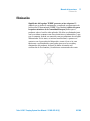
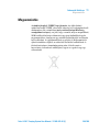
Significato del logo "WEEE" presente sulle etichette. Il simbolo qui
sotto riportato è applicato in ottemperanza alla direttiva CE
denominata "WEEE". Questo simbolo (valido solo per i paesi della
Comunità Europea) indica che il prodotto sul quale è applicato, NON
deve essere smaltito insieme ai comuni rifiuti domestici o industriali,
ma deve essere avviato ad un sistema di raccolta differenziata. Si
invita pertanto l'utente finale a contattare il fornitore del dispositivo,
sia esso la casa madre o un rivenditore, per avviare il processo di
raccolta e smaltimento, dopo opportuna verifica dei termini e
condizioni contrattuali di vendita.
Turbo-V 3K-T Pumping System User Manual / 87-900-979-01 (F)
29/388
1
Istruzioni per l’uso
Smaltimento
30/388
Turbo-V 3K-T Pumping System User Manual / 87-900-979-01 (F)
Turbo-V 3K-T Pumping System User Manual
2
Gebrauchsanleitung
Sicherheitshinweise für Turbomolekularpumpen 32
Allgemeine Informationen 33
Lagerung
35
Vor der Installation
36
Installation
38
Gebrauch
41
Benutzung der Turbo-V 3K-T
42
Ingangsetzung des Systems
42
Stillsetzung der Turbo-V 3K-T
45
Wartung
46
Entsorgung
47
Übersetzung der Originalanleitungen
31/388
2
Gebrauchsanleitung
Sicherheitshinweise für Turbomolekularpumpen
Sicherheitshinweise für Turbomolekularpumpen
Die in der folgenden Gebrauchsanweisung beschriebenen
Turbomolekularpumpen verfügen aufgrund der hohen
Rotationsgeschwindigkeit in Verbindung mit dem spezifischen
Gewicht ihrer Rotoren über eine große Menge kinetischer Energie.
Im Falle eines Systemdefekts, z.B. durch einen Kontakt zwischen
Rotor und Stator oder durch einen Rotorbruch, könnte diese
Rotationsenergie freigesetzt werden.
WARNUNG!
32/388
Um Schäden am Gerät zu vermeiden und um Verletzungen der Bediener
vorzubeugen, befolgen Sie bitte aufmerksam die in diesem Handbuch
beschriebenen Installationshinweise!
Turbo-V 3K-T Pumping System User Manual / 87-900-979-01 (F)
Gebrauchsanleitung
Allgemeine Informationen
2
Allgemeine Informationen
Dieser Apparat ist für den fachmännischen Gebrauch bestimmt. Vor
dem Gebrauch hat der Benutzer dieses Handbuch sowie alle weiteren
mitgelieferten Zusatzdokumentationen genau zu lesen. Bei auch
teilweiser Nichtbeachtung der enthaltenen Anweisungen,
unsachgemäßem Gebrauch durch ungeschultes Personal, nicht
autorisierten Eingriffen und Mißachtung der nationalen
einschlägigen Normen übernimmt die Firma Agilent keinerlei
Haftung.
Modell Turbo-V 3K-T ist ein integriertes System, das aus einer
Turbomolekularpumpe für Hoch- und Höchstvakuum-anwendungen,
integriert mit einem entsprechenden Controller, besteht. Das System
kann viele Arten von Gas oder gasförmigen Gemischen pumpen, ist
jedoch nicht für das Pumpen von Flüssigkeiten oder
Festkörperpartikeln geeignet.
Die Pumpwirkung wird durch eine hochtourige Turbine (max. 31800
1/min) erreicht, die von einem Hochleistungsdrehstrommotor
angetrieben wird. Modell Turbo-V 3K-T enthält keinerlei
umweltschädliche Substanzen und eignet sich deshalb auch für
Anwendungen, die ein "sauberes" Vakuum erfordern.
Es verfügt des Weiteren über Hilfskonnektoren, über die es von
einem Host-Rechner mit seriellem Anschluss (RS232 oder RS485)
ferngesteuert werden kann.
In den folgenden Abschnitten sind alle erforderlichen Informationen
für die Sicherheit des Bedieners bei der Anwendung des Geräts
aufgeführt. Detaillierte technische Informationen sind im Anhang
"Technical Information" enthalten.
Turbo-V 3K-T Pumping System User Manual / 87-900-979-01 (F)
33/388
2
Gebrauchsanleitung
Allgemeine Informationen
In dieser Gebrauchsanleitung werden Sicherheitshinweise
folgendermaßen hervorgehoben:
WARNUNG!
Die Warnhinweise lenken die Aufmerksamkeit des Bedieners auf einen
Vorgang oder eine bestimmte Ausführungsweise, die bei unkorrekter
Ausführung schwere Verletzungen hervorrufen könnten.
VORSICHT!
Die Vorsichtshinweise werden vor Vorgängen angegeben, die bei
Nichtbeachtung Schäden an der Anlage verursachen könnten.
HINWEIS
34/388
Die Hinweise enthalten wichtige Informationen, die aus dem Text hervorgehoben
werden.
Turbo-V 3K-T Pumping System User Manual / 87-900-979-01 (F)
Gebrauchsanleitung
Lagerung
2
Lagerung
Um ein Höchstmaß an Effizienz und Zuverlässigkeit der Agilent
Turbomolekularpumpen zu gewährleisten, sind die folgenden
Anweisungen zu beachten:
VORSICHT!
Während des Transports, der Handhabung und der Einlagerung
der Pumpen dürfen die folgenden Grenzwerte nicht überschritten
werden:
Temperatur: von –20 °C bis 70 °C
Relative Feuchtigkeit: von 0 bis 95 % (nicht kondensierend)
Der Kunde hat die Turbomolekularpumpen nach dem Empfang
bei Erstinbetriebnahme stets im Modus Soft-Start
ingangzusetzen.
Die Lagerdauer für eine Turbomolekularpumpe beträgt 10 Monate
ab dem Speditionsdatum.
Falls die Lagerdauer aus verschiedenen Gründen die genannte Frist
überschreiten sollte, ist die Pumpe an das Werk zurückzusenden. Für
Informationen wenden Sie sich bitte an den örtlichen Agilent Vertreter.
Turbo-V 3K-T Pumping System User Manual / 87-900-979-01 (F)
35/388
2
Gebrauchsanleitung
Vor der Installation
Vor der Installation
Modell Turbo-V 3K-T wird in einer speziellen Schutzverpackung
geliefert. Eventuelle Transportschäden sind der zuständigen
örtlichen Verkaufsstelle zu melden. Modell Turbo-V 3K-T ist
vorsichtig auszupacken, wobei es vor dem Herunterfallen und vor
Stößen und Vibrationen zu schützen ist. Das Verpackungsmaterial ist
vorschriftsgemäß zu entsorgen.
Den Schutz der Steckverbinder erst entfernen, wenn die Turbopumpe
am System befestigt ist.
Für die Entnahme der Pumpe aus ihrer Verpackung sind, aufgrund
des hohen Gewichtes (55 kg), die drei um 120º versetzten
Ösenschrauben zu benutzen, die am Pumpenkorpus angeschraubt
sind.
Es ist vollständig recyclebar und entspricht der Richtlinie
85/399/EWG für Umweltschutz.
VORSICHT!
HINWEIS
36/388
Um Entgasungen zu vermeiden, dürfen die Teile, die mit dem Vakuum in
Berührung kommen, nicht mit den bloßen Händen angefasst werden. Es sind stets
Schutzhandschuhe oder andere Schutzmittel zu verwenden.
Die Turbo-V 3K-T kann durch ledigliche Einwirkung von atmosphärischen
Bedingungen nicht beschädigt werden. Es wird indes empfohlen, die Pumpe bis
zur Installation am System geschlossen und versiegelt zu halten. Auf diese
Weise kann der Verunreinigung des Systems vorgebeugt werden.
Turbo-V 3K-T Pumping System User Manual / 87-900-979-01 (F)
Gebrauchsanleitung
Vor der Installation
2
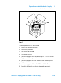
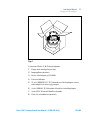
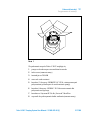
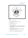
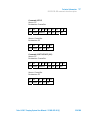
Abbildung 1
Verpackungsinhalt der Turbo-V 3K-T:
1
Pumpe mit integriertem Controller
2
Inlet-Screen (montiert)
3
Betriebsanleitung auf CD-ROM
4
Beutel mit Zubehör
5
Gegenkonnektor mit 15 PINs “REMOTE I/O” IP-54 mit
integrierten Anschlüssen für den Pumpenanlauf
6
Gegenkonnektor mit 9 PINs “SERIAL” IP-54 für den seriellen
Anschluss
7
Gegenkonnektor mit 9 PINs IP-54 "Network" MoniTorr
8
Halteschelle für das Stromversorgungskabel (montiert).
Turbo-V 3K-T Pumping System User Manual / 87-900-979-01 (F)
37/388
2
Gebrauchsanleitung
Installation
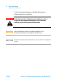
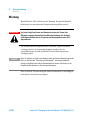
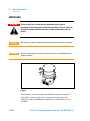
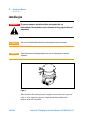
Installation
Die Pumpe ist aufgrund ihres hohen Gewichtes mit geeigneten Hebe- und
Förderzeugen zu handhaben. Zu diesen Zwecken sind die Ösenschrauben zu
benutzen, die in die Gewindebohrungen am Pumpenkorpus eingeschraubt
sind.
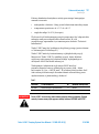
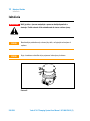
VORSICHT!
Die angeschraubte Abdeckung darf erst nach Anschluss der Turbopumpe an das
System entfernt werden.
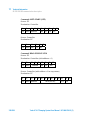
VORSICHT!
Den Schutz der Steckverbinder erst entfernen, wenn die Turbopumpe am System
befestigt ist.
WARNING
WARNUNG!
NO
YES
CH
AM
RE
MO
VE
ME
CHAN THIS
PR
ICA
L INS OTEC
TAL TION
LAT
ION AFTER
BER
Abbildung 2
Die Pumpe darf nicht in Umgebungen, die ungeschützt vor Wetter
(Regen, Frost, Schnee), Staub und aggressiven Gasen sind, sowie
auch nicht in explosionsfähigen oder erhöht brandgefährdeten
Umgebungen installiert und/oder benutzt werden.
38/388
Turbo-V 3K-T Pumping System User Manual / 87-900-979-01 (F)
Gebrauchsanleitung
Installation
2
Beim Betrieb müssen folgende Umgebungsbedingungen eingehalten
werden:
Maximaler Druck: 2 bar über dem atmosphärischen Druck
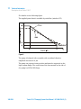
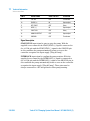
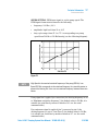
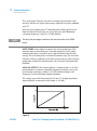
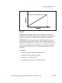
Temperatur: von +5 °C bis +40 °C (siehe Diagramm im Anhang
"Technical Information")
Relative Luftfeuchtigkeit: 0 – 95 % (nicht kondensierend).
Bei Vorhandensein von elektromagnetischen Feldern ist die Pumpe
entsprechend abzuschirmen. Für ausführliche Informationen siehe
im Anhang "Technical Information".
Modell Turbo-V 3K-T ist an eine Primärpumpe anzuschließen (siehe
Schema in "Technical Information").
Modell Turbo-V 3K-T kann in jeder beliebigen Position installiert
werden. Modell Turbo-V 3K-T ist stabil zu befestigen, indem der
Flansch am Eingang der Turbopumpe an einen festen Gegenflansch
angeschlossen wird, der mit einem Drehmoment von 43000 Nm um
seine eigene Achse belastbar ist.
Die Turbopumpe mit Eingangsflansch ISO F muss mit der
Vakuumkammer mithilfe von Bolzen Befestigungsklasse 12,9 (σr =
1200 N/mm2) befestigt werden. Die folgende Tabelle beschriebt die
Anzahl der notwendigen Stahlbolzen und den von Agilent
empfohlenen Anzugsmoment.
Tab. 1
WARNUNG!
FLANSCH
KLEMMSCHELLE
ANZ.
ANZUGSMOMENT
ISO 250 F
Mutterschraube mit Gewinde M10
12
40 Nm
Die Turbo-V 3K-T kann nicht über ihren Sockel befestigt werden. Zur
Befestigung des Systems kann nur der Flansch ISO 250F oder CFF 12“
verwendet werden.
Turbo-V 3K-T Pumping System User Manual / 87-900-979-01 (F)
39/388
2
Gebrauchsanleitung
Installation
Turbopumpen mit ConFlat Eingangsflansch sind mit dem speziellen
Agilent Befestigungsmaterial an die Vakuum kammer anzuschließen.
Für ausführliche Informationen siehe im "HIGH VACUUM FLANGE
CONNECTION".
Es sind Mutterschrauben aus Stahl mit einer Festigkeitsklasse von
mindestens 500 N/mm2 zu verwenden.
WARNUNG!
Die Nichtbeachtung dieser Anleitung, sollte sich ein Schaden am Rotor
ergeben, kann zur Loslösung der Pumpe vom System führen mit Schäden an
Dingen oder schweren Verletzungen oder zum Tod von Personen führen.
VORSICHT!
Der Turbo-V 3K-T gehört zur zweiten Installationsklasse (Überdruck) die von den
Normen EN 61010-1 vorgesehen ist. Die Vorrichtung muß daher an eine
Speisungsleitung angeschlossen werden, die dieser Kategorie entspricht. Die
Gegenstecker der Ausstattung als Zubehörteil verwenden, um die Isolierung IP54 zu gewährleisten. Der Turbo-V 3K-T hat Verbinder für den Ein-und Ausgang
und die Schnittstellenkommunikation, die an die Außenkreise angeschlossen
werden müssen, sodaß kein Teil unter Spannung zugänglich ist. Sicherstellen,
daß die Isolierung der an den Turbo-V 3K-T angeschlossenen Vorrichtung auch
bei einer Einzelstörung ausreichend isoliert, wie es von der Richtlinie EN 61010-1
vorgesehen wird.
Für die Installation der Optionsteile siehe im Anhang "Technical
Information".
40/388
Turbo-V 3K-T Pumping System User Manual / 87-900-979-01 (F)
Gebrauchsanleitung
Gebrauch
2
Gebrauch
In diesem Abschnitt werden die wichtigsten Betriebsvorgänge
erläutert. Vor Benutzung des Systems sind alle elektrischen und
pneumatischen Anschlüsse auszuführen.
Während der eventuellen Aufheizung der Vakuumkammer darf die
Temperatur am Eingangsflansch 80°C nicht überschreiten.
Während des Pumpenbetriebs darf die Temperatur des Läufers
niemals 120 °C überschreiten.
Der Bediener hat sich zu vergewissern, dass die richtige Betriebsart
in Abhängigkeit von dem zu pumpenden Gas eingestellt ist: 1 für
Stickstoff und leichtere Gase, 0 für Argon (voreingestellte
Betriebsart) in der Seriensteuerung 157. Für ausführliche
Informationen siehe im Anhang "Technical Information".
WARNUNG!
Die Pumpe darf nicht in Betrieb genommen werden, wenn der
Eingangsflansch nicht an die Vakuumkammer angeschlossen oder nicht mit
dem Verschlussflansch verschlossen ist. Während des Aufheizens dürfen
weder die Pumpe noch eventuelle heiße Zubehörteile berührt werden. Es
besteht Verbrennungsgefahr.
VORSICHT!
Während des Betriebs sind Stoß- und Vibrationseinwirkungen sowie
Ruckbewegungen an der Turbopumpe zu vermeiden, da die Lager beschädigt
werden könnten. Für die Belüftung der Pumpe trockene staub und partikelfreie
Luft oder Inertgase verwenden. Der Eingangsdruck am Belüftungsanschluß soll
unter 1 bar (über dem atmosphärischen Druck) betragen. Zum Pumpen von
Gasen mit Partikeln oder aggressiven Schadstoffe für die Lager, sind die Pumpen
mit einer Öffnungsklappe ausgestattet, über die zum Schutz der Lager Inertgas
(Stickstoff oder Helium) zuzuleiten ist (siehe Anhang "Technical Information").
Turbo-V 3K-T Pumping System User Manual / 87-900-979-01 (F)
41/388
2
Gebrauchsanleitung
Gebrauch
WARNUNG!
Wenn die Pumpe zur Förderung von giftigen, leicht entflammbaren oder
radioaktiven Gasen benutzt wird, sind die für das jeweilige Gas
vorgeschriebenen Vorgänge und Maßnahmen zu befolgen. Die Pumpe darf
niemals bei Vorhandensein von explosionsfähigen Gasen verwendet werden.
Die Pumpe ist für einen hohen Durchsatz an Stickstoff, Argon und leichteren
Gasen konzipiert. Falls das Pumpen von Gasen erforderlich ist, die schwerer
als Argon sind, ist mit dem Technischen Kundendienst von Agilent
Rücksprache zu halten.
Benutzung der Turbo-V 3K-T
Ingangsetzung des Systems
Vor der Ingangsetzung des Systems ist zu kontrollieren, dass der E/AGegenkonnektor entfernt ist. Wenn das System an eine Vorrichtung
für die Ferneingabe/-ausgabe angeschlossen ist, ist zu überprüfen,
dass das Signal STOP aktiv ist (siehe Abschnitt "J1 – REMOTE I/O "
im Anhang "Technical Information").
Zur Ingangsetzung des Systems sind die folgenden Schritte
auszuführen:
42/388
1
E/A-Gegenkonnektor entfernen (sofern vorhanden)
2
Gerät an das Netz anschließen
3
Druck in der Vakuumkammer auf 0,1 mbar bringen.
4
Für die Erteilung des Signals START an die Turbo-V 3K-T gibt es
die folgenden Möglichkeiten:
a
Mitgelieferten E/A-Gegenkonnektor anschließen.
b
Das Signal START von der Fernsteuerung über den E/AKonnektor geben (siehe Abschnitt "J1 – REMOTE I/O" im
Anhang "Technical Information").
c
Das Signal START von der Fernsteuerung über die serielle
Schnittstelle RS 232/485 geben (siehe Abschnitt "RS 232/485
Communication Description" im Anhang "Technical
Information").
Turbo-V 3K-T Pumping System User Manual / 87-900-979-01 (F)
Gebrauchsanleitung
Gebrauch
WARNUNG!
Wenn die Spannung zugeschaltet und der Gegenkonnektor mit 15 PINs
angeschlossen ist, startet die Turbo-V 3K-T automatisch.
VORSICHT!
Im Lieferumfang ist der mechanisch und elektrisch an die Pumpe
angeschlossene Controller enthalten. Die Trennung des Controllers vom
Pumpenkorpus darf nur von Personen ausgeführt werden, die von Agilent
Vacuum Technologies autorisiert sind.
2
HINWEIS
Bei Erstingangsetzung der Turbo-V 3K-T startet der Controller das System mit
einer Spezialprozedur, um die Kugellager vor etwaigen Schäden zu schützen
(SOFT START). Das System wird innerhalb von 1 Stunde in aufeinander folgenden
Schritten bis zur Arbeitsgeschwindigkeit gestartet. Sobald das System die
Arbeitsgeschwindigkeit erreicht hat, wird die "soft start"-Prozedur deaktiviert. Die
darauf folgenden Anlaufvorgänge werden normal ausgeführt.
HINWEIS
Zur Beibehaltung des Schutzniveaus IP-54 ausschließlich die mit der Pumpe
gelieferten Steckverbinder anwenden. Für das Stromversorgungskabel dürfen nur
die PN 969-9957 oder 969-9958 verwendet werden. Das Kabel ist am Controller
mit der hierfür vorgesehenen Schelle zu befestigen (siehe nachstehende
Abbildung). Dieses Kabel und Stecker zusammen mit einer korrekt an der Erde
angeschlossenen Steckdose verwenden, um Stromstöße zu vermeiden und den
EG-Bestimmungen zu entsprechen.
Turbo-V 3K-T Pumping System User Manual / 87-900-979-01 (F)
43/388
2
Gebrauchsanleitung
Gebrauch
Abbildung 3
Das System wird mit einer grünen LED geliefert, die von einem
Statussignal angesteuert wird.
Die grüne LED LD1 an der Bodenplatte von Modell Turbo-V 3K-T gibt
mit der Häufigkeit ihres Blinkens die Betriebsbedingungen des
System an:
44/388
Daueranzeige: Die Pumpe befindet sich im normalen Betrieb.
Langsame Blinkanzeige (ca. 400 ms): das System befindet sich
entweder im Status Rampe, Abbremsung, Stopp oder “Waiting for
Interlock”.
Schnelle Blinkanzeige (ca. 200 ms): Fehlerstatus.
Turbo-V 3K-T Pumping System User Manual / 87-900-979-01 (F)
Gebrauchsanleitung
Gebrauch
2
Stillsetzung der Turbo-V 3K-T
Für die Stillsetzung der Pumpe gibt es die folgenden Möglichkeiten:
1
Mitgelieferten E/A-Konnektor entfernen.
2
Das Signal STOP von der Fernsteuerung über den E/A-Konnektor
geben (siehe Abschnitt "J1 – REMOTE I/O" im Anhang "Technical
Information").
3
Das Signal STOP von der Fernsteuerung über die serielle
Schnittstelle RS 232/485 geben (siehe Abschnitt "RS 232/485
Communication Description" im Anhang "Technical
Information").
Turbo-V 3K-T Pumping System User Manual / 87-900-979-01 (F)
45/388
2
Gebrauchsanleitung
Wartung
Wartung
Modell Turbo-V 3K-T erfordert keine Wartung. Eventuelle Eingriffe
dürfen nur von autorisiertem Fachpersonal ausgeführt werden.
WARNUNG!
Vor jedem Eingriff am System den Netzstecker ziehen, die Pumpe über
Öffnung des entsprechenden Ventils belüften und abwarten, bis der Rotor
vollkommen stillsteht und die Temperatur am Pumpengehäuse unter 50 °C
abgesunken ist.
Bei Defekten kann der Agilent Service oder der "Agilent advanced
exchange service" in Anspruch genommen werden, der ein
generalüberholtes System als Ersatz für das defekte System zur
Verfügung stellt.
HINWEIS
Bevor Fa. Agilent ein System zur Reparatur oder den Umtauschdienst eingesandt
wird, ist das Formular "Sicherheit und Gesundheit", das diesem Handbuch
beiliegt, ausgefüllt an die örtliche Verkaufsstelle zu senden. Eine Kopie ist der
Verpackung des Systems vor dem Versand beizulegen.
Eine eventuelle Verschrottung hat unter Beachtung der einschlägigen
nationalen Vorschriften zu erfolgen.
46/388
Turbo-V 3K-T Pumping System User Manual / 87-900-979-01 (F)
Gebrauchsanleitung
Entsorgung
2
Entsorgung
Bedeutung des "WEEE" Logos auf den Etiketten. Das folgende
Symbol ist in Übereinstimmung mit der EU-Richtlinie WEEE (Waste
Electrical and Electronic Equipment) angebracht. Dieses Symbol (nur
in den EU-Ländern gültig) zeigt an, dass das betreffende Produkt
nicht zusammen mit Haushaltsmüll entsorgt werden darf sondern
einem speziellen Sammelsystem zugeführt werden muss. Der
Endabnehmer sollte daher den Lieferanten des Geräts - d.h. die
Muttergesellschaft oder den Wiederverkäufer - kontaktieren, um den
Entsorgungsprozess zu starten, nachdem er die Verkaufsbedingungen
geprüft hat.
Turbo-V 3K-T Pumping System User Manual / 87-900-979-01 (F)
47/388
2
Gebrauchsanleitung
Entsorgung
48/388
Turbo-V 3K-T Pumping System User Manual / 87-900-979-01 (F)
Turbo-V 3K-T Pumping System User Manual
3
Mode d’emploi
Normes de sécurité pour Pompe Turbomoléculaires
Indications generales 51
Stockage
53
Preparation pour l‘installation 54
Installation
56
Utilisation
59
Utilisation de la pompe Turbo-V 3K-T 60
Mise en marche du système 60
Arrêt du système 63
Arrêt d’urgence 63
Entretien
64
Mise au rebut
65
50
Traduction de la mode d’emploi originale
49/388
3
Mode d’emploi
Normes de sécurité pour Pompe Turbomoléculaires
Normes de sécurité pour Pompe Turbomoléculaires
Les pompes Turbomoléculaires décrites dans le Manuel
d'Instructions suivant ont une énergie cinétique élevée due à la
grande vitesse de rotation associée à la masse spécifique de leurs
rotors.
En cas de panne du système, par exemple à cause d'un contact entre
rotor et stator ou d'une rupture du rotor, l'énergie de rotation
pourrait être libérée.
AVERTISSEMENT! Pour éviter tout dégât aux appareillages et empêcher toute blessure aux
opérateurs, il faut suivre attentivement les instructions d'installation
décrites dans ce manuel!
50/388
Turbo-V 3K-T Pumping System User Manual / 87-900-979-01 (F)
Mode d’emploi
Indications generales
3
Indications generales
Cet appareillage a été conçu en vue d'une utilisation professionnelle.
Avant toute utilisation de l'appareil, il est conseillé à l'utilisateur de
lire attentivement cette notice d'instructions ainsi que toute autre
indication supplémentaire fournie par Agilent qui décline par
conséquent toute responsabilité en cas de non respect total ou partiel
des instructions données, d'utilisation impropre par un personnel
non formé, d'opérations non autorisées ou d'emploi contraire aux
réglementations nationales spécifiques.
Le Turbo-V 3K-T est un système intégré, constitué d'une pompe
turbomoléculaire conçue pour des applications de vide poussé et
ultrapoussé et doté d'un contrôleur Le système est en mesure de
pomper de nombreux types de gaz ou de composés gazeux, mais il
n’est pas adapté au pompage de liquides ou de particules solides.
L'effet de pompage est obtenu grâce à une turbine tournant à vitesse
élevée (31800 tr/min maxi), mue par un moteur électrique triphasé à
haut rendement. Le Turbo-V 3K-T est totalement exempt d'agents
polluants et il est par conséquent indiqué pour toutes les
applications exigeant un vide "propre".
Il est en outre doté de connecteurs auxiliaires qui permettent de le
piloter à distance à travers un ordinateur central connecté à travers
une ligne sérielle (RS232 ou RS485).
Les paragraphes suivants fournissent toutes les indications
nécessaires à garantir la sécurité de l'opérateur pendant l'utilisation
de l'appareillage. Des renseignements plus détaillés se trouvent dans
l'appen-dice "Technical Information".
Turbo-V 3K-T Pumping System User Manual / 87-900-979-01 (F)
51/388
3
Mode d’emploi
Indications generales
Cette notice utilise les signes conventionnels suivants:
AVERTISSEMENT! Les messages d’avertissement attirent l'attention de l'opérateur sur une
procédure ou une manoeuvre spéciale qui, si elle n'est pas effectuée
correctement, risque de provoquer de graves lésions.
ATTENTION!
NOTE
52/388
Les messages d'attention apparaissent avant certaines procédures qui, si elles
ne sont pas observées, pourraient endommager sérieusement l'appareillage.
Les notes contiennent des renseignements importants, isolés du texte.
Turbo-V 3K-T Pumping System User Manual / 87-900-979-01 (F)
Mode d’emploi
Stockage
3
Stockage
Pour garantir les performances et la fiabilité maximales des pompes
turbomoléculaires Agilent, il est indispensable de respecter les
instructions suivantes :
ATTENTION!
Le transport, la manutention et le stockage des pompes, doivent
impérativement avoir lieu dans les conditions ambiantes
suivantes:
température : de –20 °C à +70 °C
humidité relative : de 0 à 95 % (non condensante)
A la première utilisation, les pompes turbomoléculaires doivent
toujours être mises en marche en mode soft-Start.
Le temps de stockage d'une pompe turbomoléculaire est de 10
mois à compter de la date d'expédition.
En cas de dépassement du temps de stockage, la pompe doit être retournée en
usine. Pour tout renseignement, contacter le représentant Agilent de zone.
Turbo-V 3K-T Pumping System User Manual / 87-900-979-01 (F)
53/388
3
Mode d’emploi
Preparation pour l‘installation
Preparation pour l‘installation
Le Turbo-V 3K-T est livré dans un emballage de protection spécial; en
cas d'endommagement de l'emballage pouvant s'être produit pendant
le transport, contacter le bureau de vente local.
Pendant l'opération d'ouverture de l'emballage, veiller tout
particulièrement à ne pas laisser tomber le Turbo-V 3K-T et à ne lui
faire subir aucun choc et aucune vibration.
Enlever la protection des connecteurs seulement après avoir fixée la
turbopompe au système.
Compte tenu de son poids (55 kg), il est nécessaire d’utiliser les trois
anneaux de levage à 120° vissé sur le corps de la pompe pour
l’extraire de son emballage.
Ne pas abandonner l'emballage dans la nature. Le matériel est
entièrement recyclable et conforme à la directive CEE 85/399 en
matière de protection de l'environnement.
ATTENTION!
Afin d'éviter tout problème de dégazage, ne pas toucher, à mains nues, les
éléments devant être exposés au vide. Mettre toujours des gants ou toute autre
protection appropriée.
NOTE
La Turbo-V 3K-T ne peut être endommagée par une exposition
environnementale normale. Toutefois, il est conseillé de maintenir la pompe
fermée et scellée jusqu'à son installation dans le système. Ceci afin de prévenir
toute contamination du système.
54/388
Turbo-V 3K-T Pumping System User Manual / 87-900-979-01 (F)
Mode d’emploi
Preparation pour l‘installation
3
Figure 1
La pompe Turbo-V 3K-T comprend:
1
Pompe avec contrôleur intégré
2
Protection d’entrée (montée)
3
CD-Rom contenant cette notice d’utilisation
4
Sachet d’accessoires
5
Connecteur à 15 voies “REMOTE I/O” IP-54 avec toutes les
connexions nécessaires à la mise en marche de la pompe
6
Connecteur à 9 voies “SERIAL” IP-54 à utiliser pour la connexion
sérielle
7
Connecteur à 9 voies IP-54 pour le "Network" MoniTorr
8
Bride de retenue du câble d’alimentation (montée).
Turbo-V 3K-T Pumping System User Manual / 87-900-979-01 (F)
55/388
3
Mode d’emploi
Installation
Installation
AVERTISSEMENT! Étant donné son poids, la pompe doit être manipulée à l’aide des
équipements de levage et de déplacement appropriés. Utiliser les anneaux
de levage vissés dans les orifices filetés sur le corps de la pompe.
Ne jamais retirer la protection boulonnée avant le branchement de la turbo
pompe au système.
ATTENTION!
Enlever la protection des connecteurs seulement après avoir fixée la
turbopompe au système.
WARNING
ATTENTION!
NO
YES
CH
AM
BER
RE
MO
VE
ME
THIS
CH
AN
PR
ICA
L INS OTEC
TAL TION
LAT
ION AFTER
Figure 2
56/388
Turbo-V 3K-T Pumping System User Manual / 87-900-979-01 (F)
Mode d’emploi
Installation
3
Ne pas installer et/ou utiliser la pompe dans des milieux exposés aux
agents atmosphériques (pluie, gel, neige), à la poussière, aux gaz
agressifs ainsi que dans des milieux explosifs ou à fort risque
d'incendie.
Pendant le fonctionnement, il est nécessaire de respecter les
conditions environnementales suivantes:
pression maxi: 2 bar au-delà de la pression atmosphérique
température: de +5 °C à +40 °C (Cf. graphique dans "Technical
Information")
humidité relative: 0 – 95 % (non condensante)
En présence de champs magnétiques, la pompe doit être protégée à
l'aide d'écrans appropriés. Pour tout autre renseignement, se
reporter à l'opuscule "Technical Information". Le Turbo-V 3K-T doit
être connecté à une pompe primaire (Cf. schéma dans "Technical
Information"). Le Turbo-V 3K-T peut être installée dans n'importe
quelle position.
Le fixer dans une position stable, en reliant la bride d'entrée de la
turbopompe à une contre-bride fixe pouvant supporter un couple de
serrage de 43000 Nm autour de son axe.
La turbopompe à bride d’entrée ISO F doit être fixée à la chambre à
vide par des boulons d’une classe de fixation de 12,9 (σr = 1200
N/mm2). Le tableau ci-dessous indique le nombre de boulons en acier
nécessaires et le couple de serrage préconisé par Agilent.
Tab. 1
BRIDE
TYPE DE COLLIER
N.
COUPLE DE SERRAGE
ISO 250 F
Boulon à filet M10
12
40 Nm
AVERTISSEMENT! La Turbo pompe V 3K-T ne peut être fixée à l’aide de son socle. Le
système peut être fixé uniquement à l’aide de sa bride ISO 250F ou CFF
12".
Turbo-V 3K-T Pumping System User Manual / 87-900-979-01 (F)
57/388
3
Mode d’emploi
Installation
La turbopompe à bride d'entrée ConFlat doit être fixée à la chambre
à vide à l'aide des éléments mécaniques Agilent prévus à cet effet.
Pour tout autre détail, se reporter à "HIGH VACUUM FLANGE
CONNECTION".
Il est nécessaire d’utiliser des boulons en acier ayant une classe de
résistance minimum de 500 N/mm2.
AVERTISSEMENT! Le non-respect des instructions de montage peut provoquer un décrochage
de la pompe du système en cas de panne du rotor et entraîner des
dommages aux biens et de graves préjudices, voire la mort, aux personnes.
ATTENTION!
Le Turbo-V 3K-T appartient à la deuxième catégorie d'installations (ou
surtension) prévue par la norme EN 61010-1. De ce fait, brancher le dispositif à
une ligne d'alimentation compatible avec cette catégorie. Utiliser les contre
connecteurs fournis en dotation pour garantir l'isolation IP-54. Le Turbo-V 3K-T
dispose de connecteurs pour les en-trées/sorties et pour la communication en
série qui doivent être branchés aux circuits extérieurs de façon qu'aucune
partie sous tension ne soit accessible. S'assurer que l'isolation du dispositif
branché au Turbo-V 3K-T a une isolation appropriée même en condition de
panne individuelle selon les termes de la norme EN 61010-1.
Pour l'installation des accessoires en option, se reporter à "Technical
Information".
58/388
Turbo-V 3K-T Pumping System User Manual / 87-900-979-01 (F)
Mode d’emploi
Utilisation
3
Utilisation
Ce paragraphe présente les principales procédures opérationnelles.
Avant d'utiliser le système, effectuer tous les branchements
électriques et pneumatiques. Pendant le chauffage éventuel de la
chambre à vide, la température de la bride d'entrée ne doit pas
dépasser 80 °C.
Pendant le fonctionnement de la pompe, la température du rotor ne
doit jamais être supérieure à 120 °C.
L'opérateur doit veiller à adapter le mode de fonctionnement correct
au gaz à pomper: 1 pour azote et gaz plus légers, 0 pour Argon (mode
défaut) dans la commande sérielle 157. Pour plus de détails,
consulter l’appendice "Technical Information".
AVERTISSEMENT! Ne jamais faire fonctionner la pompe si la bride d'entrée n'est pas reliée à la
chambre à vide ou si elle n'est pas fermée avec la bride de fermeture. Eviter
de toucher la turbopompe ainsi que ses accessoires éventuels pendant les
opérations de chauffage. La température élevée peut être à l'origine de
lésions graves.
ATTENTION!
Lorsque la turbopompe fonctionne, éviter tout choc, oscillation ou déplacement
brusque car les paliers pourraient se détériorer. Pour le refoulement de l'air de la
pompe, utiliser de l'air ou du gaz inerte exempt de poussière ou de particules. La
pression d'entrée à travers la porte prévue à cet effet doit être inférieure à 1 bar
(au-delà de la pression atmosphérique). Pour le pompage de gaz agressifs, ces
pompes sont dotées d'une porte spéciale à travers laquelle il est nécessaire de
fournir à la pompe un flux de gaz inerte (Azote ou Hélium) pour protéger les
paliers (voir l'appendice "Technical Information").
Turbo-V 3K-T Pumping System User Manual / 87-900-979-01 (F)
59/388
3
Mode d’emploi
Utilisation
AVERTISSEMENT! Lorsque la pompe est utilisée pour le pompage de gaz toxiques, inflammables
ou radioactifs, suivre les procédures typiques de chaque gaz. Ne pas utiliser
la pompe en présence de gaz explosifs. La pompe est conçue pour garantir
un transfert élevé de l’azote, de l’argon et des gaz plus légers. En cas de
pompage de gaz plus lourds que l’argon, contacter le service technique
Agilent pour informations.
Utilisation de la pompe Turbo-V 3K-T
Mise en marche du système
Avant la mise en marche du système, contrôler que le connecteur E/S
soit débranché. Si le système est connecté à un dispositif
Entrée/Sortie à distance, s’assurer que le signal de STOP soit activé
(voir paragraphe “J1 – REMOTE I/O – [J1 – E/S À DISTANCE”] dans
l’appendice "Technical Information").
Pour démarrer le système, effectuer les opérations suivantes :
60/388
1
Retirer (si monté) le connecteur E/S.
2
Connecter au réseau.
3
Porter la pression à l’intérieur de la chambre à vide à 0,1 mbar.
4
Donner à la pompe Turbo-V 3K-T le signal de START de l’une des
façons suivantes :
a
Brancher le connecteur E/S fourni.
b
Donner le signal de START à distance à travers le connecteur
E/S (Cf. paragraphe "J1 – REMOTE I/O [E/S À DISTANCE]"
dans l’appendice "Technical Information").
c
Donner le signal de START à distance à travers l’interface
sérielle RS 232/485 (Cf. paragraphe "RS 232/485
Communication Description [Description communication]"
dans l’appendice "Technical Information").
Turbo-V 3K-T Pumping System User Manual / 87-900-979-01 (F)
Mode d’emploi
Utilisation
3
AVERTISSEMENT! Lorsque le système est branché au réseau et que le connecteur à 15 broches
est connecté, la pompe Turbo-V 3K-T se met automatiquement en marche.
ATTENTION!
Le contrôleur est fourni déjà connecté (connexion mécanique et électrique) à la
pompe. La séparation du contrôleur du corps de la pompe peut être effectuée
uniquement par le personnel autorisé par la société Agilent Vacuum
Technologies.
NOTE
Lors de la première mise en marche de la pompe Turbo-V 3K-T le contrôleur
lance automatiquement le système en exécutant une procédure spéciale qui
protège les paliers contre tout risque d’endommagement (SOFT START). Le
système est lancé progressivement jusqu’à ce qu’il atteigne la vitesse
maximum, en un temps d’une heure. Dès que le système atteint sa vitesse
maximum, la procédure de "soft start" est désactivée et les démarrages
suivants sont effectués en mode normal.
NOTE
Pour maintenir le niveau de protection IP-54 utiliser exclusivement les
connecteurs fournis avec la pompe. Pour l’alimentation, utiliser exclusivement
un câble type PN: 969-9957 ou 969-9958, et le fixer au contrôleur à l’aide de la
bride prévue (voir la figure ci-dessous). Utiliser ce câble et la fiche avec une
prise de courant branchée à terre pour éviter les décharges électriques et
satisfaire les prescriptions des normes CE.
Turbo-V 3K-T Pumping System User Manual / 87-900-979-01 (F)
61/388
3
Mode d’emploi
Utilisation
Figure 3
Le système est muni d’un LED vert piloté par un signal d’état.
La LED verte LD1 placée sur le panneau de la base du Turbo-V 3K-T
indique, par sa fréquence de clignotement, les conditions
opérationnelles du système:
62/388
allumée fixe: la pompe est en rotation normale;
clignote lentement (période d'environ 400 ms): le système est en
état de rampe, de freinage, de stop ou d’attente interlock.
clignote rapidement (pédiode d'environ 200 ms): condition
d'erreur.
Turbo-V 3K-T Pumping System User Manual / 87-900-979-01 (F)
Mode d’emploi
Utilisation
3
Arrêt du système
Pour arrêter la pompe, opérer dans l’un des modes suivants :
1
Débrancher le connecteur E/S.
2
Envoyer un signal de STOP à distance à travers le connecteur E/S
(Cf. paragraphe "J1 – REMOTE I/O [E/S À DISTANCE]" dans
l’appendice "Technical Information").
3
Envoyer un signal de STOP à distance via l’interface sérielle RS
232/485 (Cf. paragraphe "RS 232/485 Communication
Description" dans l’appendice "Technical Information").
Arrêt d’urgence
Pour arrêter le Turbo-V 3K-T en conditions d'urgence, il faut
débrancher le cordon d'alimentation du contrôleur.
Turbo-V 3K-T Pumping System User Manual / 87-900-979-01 (F)
63/388
3
Mode d’emploi
Entretien
Entretien
Le Turbo-V 3K-T n'exige aucun entretien particulier. Toute
intervention doit être effectuée par un personnel agréé.
AVERTISSEMENT! Avant toute intervention sur le système, le débrancher, refouler l'air de la
pompe en ouvrant la soupape prévue à cet effet, attendre jusqu'à l'arrêt
complet du rotor et jusqu'à ce que la température superficielle de la pompe
soit inférieure à 50 °C.
En cas de panne, il est possible de bénéficier du service réparations
Agilent ou du "Agilent advanced exchange service" qui permet
d'obtenir un système régénéré en remplacement du système
endommagé.
NOTE
Avant de renvoyer une pompe au constructeur pour réparation ou "advanced
exchange service", remplir et faire parvenir au bureau Agilent de votre région la
fiche "Sécurité et Santé" jointe au présent manuel d'instructions. Une copie de
cette fiche devra être mise dans l'emballage de la pompe avant l'expédition.
En cas de mise au rebut de la pompe, procéder à son élimination
conformément aux réglementations nationales concernant la gestion
des déchets.
64/388
Turbo-V 3K-T Pumping System User Manual / 87-900-979-01 (F)
Mode d’emploi
Mise au rebut
3
Mise au rebut
Signification du logo "WEEE" figurant sur les étiquettes. Le
symbole ci-dessous est appliqué conformément à la directive CE
nommée "WEEE". Ce symbole (uniquement valide pour les pays de
la Communauté euro-péenne) indique que le produit sur lequel il est
appliqué NE doit PAS être mis au rebut avec les ordures ména-gères
ou les déchets industriels ordinaires, mais passer par un système de
collecte sélective. Après avoir vérifié les termes et conditions du
contrat de vente, l’utilisateur final est donc prié de contacter le
fournisseur du dispositif, maison mère ou revendeur, pour mettre en
œuvre le processus de collecte et mise au rebut.
Turbo-V 3K-T Pumping System User Manual / 87-900-979-01 (F)
65/388
3
Mode d’emploi
Mise au rebut
66/388
Turbo-V 3K-T Pumping System User Manual / 87-900-979-01 (F)
Turbo-V 3K-T Pumping System User Manual
4
Manual de istrucciones
Indicaciones de Seguridad para Bombas Turbomoleculares 68
Información general 69
Almacenamiento 71
Preparación para la instalación 72
Instalación
74
Uso 77
Uso de Turbo-V 3K-T
78
Cómo poner en funcionamiento el sistema
78
Cómo detener la Turbo-V 3K-T 81
Parada de Emergencia 81
Mantenimiento 82
Eliminación
83
Traducción de las instrucciones originales
67/388
4
Manual de istrucciones
Indicaciones de Seguridad para Bombas Turbomoleculares
Indicaciones de Seguridad para Bombas
Turbomoleculares
Las bombas Turbomoleculares descritas en el siguiente manual de
instrucciones tienen una elevada cantidad de energía cinética debido
a la alta velocidad de rotación en combinación a la masa específica
de sus rotores.
En el caso de un daño del sistema, por ejemplo por un contacto entre
el rotor y el estator o por una rotura del rotor, la energía de rotación
podría ser liberada.
¡ADVERTENCIA! Para evitar daños a los equipos y prevenir lesiones a los operadores, es
necesario seguir atentamente las instrucciones de instalación descritas en el
presente manual!
68/388
Turbo-V 3K-T Pumping System User Manual / 87-900-979-01 (F)
Manual de istrucciones
Información general
4
Información general
Este equipo es para uso profesional. El usuario ha de leer
atentamente el presente manual de instrucciones y cualquier otra
información suplementaria facilitada por Agilent antes de usar el
aparato. Agilent se considera libre de posibles responsabilidades
debidas al incumplimiento total o parcial de las instrucciones, al uso
impropio por parte de personal no preparado, a operaciones no
autorizadas o a un uso contrario a las normas nacionales específicas.
El sistema está en condiciones de bombear diferentes tipos de gas y
de compuestos gaseosos pero no es adecuado para bombear líquidos
ni partículas sólidas.
El efecto de bombeo se obtiene mediante una turbina rotativa de alta
velocidad (31800 r.p.m. máx.) movida por un motor eléctrico trifásico
de alto rendimiento. El Turbo-V 3K-T no posee ningún agente
contaminante y por lo tanto es adecuado para aplicaciones que
requieren un vacío’ “limpio”.
Además cuenta con conectores auxiliares mediante los cuales es
posible pilotearlo de remoto a través de un ordenador host conectado
con línea serie (RS232 o RS485).
A continuación se facilita toda la información necesaria para
garantizar la seguridad del operador al usar el aparato. En el anexo
“Technical Information” se facilita información más detallada.
Turbo-V 3K-T Pumping System User Manual / 87-900-979-01 (F)
69/388
4
Manual de istrucciones
Información general
Este manual utiliza los símbolos convencionales siguientes:
¡ADVERTENCIA! Los mensajes de advertencia atraen la atención del operador sobre un
procedimiento o una operación específica que, al no realizarse
correctamente, podría provocar graves lesiones personales.
¡ATENCIÓN!
NOTA
70/388
Los mensajes de atención se visualizan antes de los procedimientos que, de no
cumplirse, podrían provocar daños al aparato.
Las notas contienen información importante extraída del texto.
Turbo-V 3K-T Pumping System User Manual / 87-900-979-01 (F)
Manual de istrucciones
Almacenamiento
4
Almacenamiento
Para garantizar el nivel máximo de funcionalidad y fiabilidad de las
bombas turbomoleculares Agilent, deberán aplicarse las siguientes
instrucciones:
¡ATENCIÓN!
durante el transporte, desplazamiento y almacenamiento de las
bombas no deberán superarse las siguientes condiciones
ambientales:
temperatura: entre –20 °C y 70 °C;
humedad relativa: entre 0 y 95 % (no condensante);
el cliente deberá activar siempre las bombas turbomoleculares en
modalidad Soft-Start al recibirlas y ponerlas en funcionamiento
por primera vez;
el período máximo de almacenamiento de una bomba
turbomolecular es de diez meses a contar de la fecha de envío al
cliente.
En caso de superarse por cualquier motivo el período máximo permitido de
almacenamiento, será necesario devolver la bomba al fabricante. Para mayores
informaciones al respecto, se ruega contactar con el representante local de
Agilent.
Turbo-V 3K-T Pumping System User Manual / 87-900-979-01 (F)
71/388
4
Manual de istrucciones
Preparación para la instalación
Preparación para la instalación
El Turbo-V 3K-T se suministra en un embalaje especial de protección;
si se observan daños, que podrían haberse producido durante el
transporte, ponerse en contacto con la oficina local de ventas.
Durante la operación de desembalaje, tener cuidado de que no se
caiga el Turbo-V 3K-T y de no someterlo a golpes o vibraciones.
Quitar la protección de los conectores solamente después de haber
fijado al sistema la turbobomba.
Debido a su peso (55 kg) para extraer la bomba del embalaje deben
utilizarse las tres armellas en 120° que se encuentran enroscadas en
el cuerpo bomba.
No abandonar el embalaje en el medio ambiente. El material es
completamente reciclable y cumple con la directiva CEE 85/399 para
la preservación del medio ambiente.
¡ATENCIÓN!
Para evitar problemas de desgasificación, no tocar con las manos desnudas los
componentes destinados a exponerse al vacío. Utilizar siempre guantes u otra
protección adecuada.
NOTA
La Turbo-V 3K-T no puede sufrir daños sólo por quedar expuesta a la acción de la
atmósfera. No obstante, se aconseja mantener la bomba cerrada y sellada hasta
el momento de instalarla en el sistema a fin de prevenir la contaminación del
mismo.
72/388
Turbo-V 3K-T Pumping System User Manual / 87-900-979-01 (F)
Manual de istrucciones
Preparación para la instalación
4
Figura 1
El embalaje de la Turbo-V 3K-T contiene:
1
bomba con controlador integrado
2
inlet screen (montado)
3
el presente manual en CD-ROM
4
bolsa con accesorios
5
ensamble de conector de 15 vías “REMOTE I/O” IP-54 que incluye
las conexiones necesarias para reactivar la bomba
6
ensamble de conector de 9 vías “SERIAL” IP-54 a utilizar para
efectuar la conexión serie
7
ensamble de conector de 9 vías IP-54 "Network" MoniTorr
8
abrazadera para retener el cable de alimentación (montada).
Turbo-V 3K-T Pumping System User Manual / 87-900-979-01 (F)
73/388
4
Manual de istrucciones
Instalación
Instalación
¡ADVERTENCIA! Siempre a causa de su peso, la bomba debe ser manejada utilizando medios
específicos de elevación y desplazamiento. Para ello deben utilizarse las
correspondientes armellas enroscadas en los respectivos agujeros
practicados en el cuerpo de la bomba misma.
No retirar la cubierta empernada antes de haber conectado la bomba de turbina
al sistema.
¡ATENCIÓN!
Quitar la protección de los conectores solamente después de haber fijado al
sistema la turbobomba.
WARNING
¡ATENCIÓN!
NO
YES
CH
AM
RE
MO
VE
ME
CHAN THIS
PR
ICA
L INS OTEC
TAL TION
LAT
ION AFTER
BER
Figura 2
No instalar ni/o utilizar la bomba en lugares expuestos a agentes
atmosféricos (lluvia, hielo y nieve), polvo y gases agresivos, en
lugares explosivos o con alto riesgo de incendio.
74/388
Turbo-V 3K-T Pumping System User Manual / 87-900-979-01 (F)
Manual de istrucciones
Instalación
4
Durante el funcionamiento es necesario que se respeten las
condiciones ambientales siguientes:
presión máxima: 2 bares por encima de la presión atmosférica
temperatura: de +5 °C a +40 °C (véase gráfico en el anexo
“Technical Information”)
humedad relativa: 0-95 % (no condensadora).
Cuando existan campos electromagnéticos, la bomba ha de
protegerse mediante pantallas oportunas. Véase el anexo “Technical
Information” para más detalles.
El Turbo-V 3K-T ha de conectarse a una bomba primaria (véase
diagrama en “Technical Information”).
El Turbo-V 3K-T puede instalarse en cualquier posición. Fijar el
Turbo-V 3K-T en posición estable conectando la brida de entrada de
la turbobomba a una contrabrida fija que puede resistir a un par de
43000 Nm alrededor de su eje.
La turbo-bomba con brida de entrada ISO F debe fijarse a la cámara
de vacío con bulones de fijación de 12,9 (σr = 1200 N/mm2). La
siguiente tabla, describe el número de bulones de acero necesarios y
el par de apriete aconsejado por Agilent.
Tab. 1
BRIDA
TIPO DE MORDAZA
N.
PAR DE APRIETE
ISO 250 F
Perno con rosca M10
12
40 Nm
¡ADVERTENCIA! La Turbo-V 3K-T no puede ser fijada por medio de su ba-se. El sistema puede
fijarse únicamente mediante su brida ISO 250F o CFF 12".
Turbo-V 3K-T Pumping System User Manual / 87-900-979-01 (F)
75/388
4
Manual de istrucciones
Instalación
La turbobomba con brida de entrada ConFlat ha de fijarse a la
cámara de vacío mediante los accesorios mecánicos específicos
Agilent. Para más detalles véase "HIGH VACUUM FLANGE
CONNECTION".
Deben utilizarse pernos de acero cuya clase de resistencia sea de al
menos 500 N/mm2.
¡ADVERTENCIA!
¡ATENCIÓN!
El incumplimiento de estas instrucciones de instalación, en el caso de que se
verifique una avería del rotor, puede provocar la separación de la bomba de la
instalación con daños a las cosas o daños graves o muerte de las personas.
El Turbo-V 3K-T pertenece a la segunda categoría de instalación (o sobretensión)
prevista por la normativa EN 61010-1. Por lo tanto este dispositivo debe ser
conectado a una línea de alimentación adecuada para dicha categoría. Usar los
contra-conectores suministrados con el equipo para garantizar el aislamiento IP54. El Turbo-V 3K-T tiene conectores para las entradas/salidas y para la
comunicación serial que deben ser conectados a los circuitos externos de
manera que ninguna parte bajo tensión quede accesible. Controlar que el
aislamiento del dispositivo conectado al Turbo-V 3K-T mantenga una acción
aisladora incluso en caso de verificarse una avería, de conformidad con lo
establecido por la normativa EN 61010-1.
Para instalar los accesorios opcionales, véase “Technical
Information”.
76/388
Turbo-V 3K-T Pumping System User Manual / 87-900-979-01 (F)
Manual de istrucciones
Uso
4
Uso
En este apartado se citan los procedimientos operativos principales.
Antes de usar el sistema realizar todas las conexiones eléctricas y
neumáticas. Durante el posible calentamiento de la cámara de vacío,
la temperatura de la brida de entrada no ha de ser superior a 80ºC.
Durante el funcionamiento de la bomba la temperatura del rotor no
deberá superar nunca los 120 °C.
El operador deberá verificar siempre que el modo de funcionamiento
que ha predispuesto sea adecuado para el gas que se debe bombear,
esto es: 1 para nitrógeno y gases más ligeros, 0 para argón (modo
predeterminado) en el mando serial 157. Para mayores detalles véase
el apéndice "Technical Information".
¡ADVERTENCIA! No hacer funcionar nunca la bomba si la brida de entrada no está conectada
al sistema o no está cerrada con la brida de cierre. No tocar la turbobomba y
sus posibles accesorios durante las operaciones de calentamiento. La alta
temperatura puede provocar lesiones a las personas.
¡ATENCIÓN!
Evítense golpes, oscilaciones o bruscos desplazamientos de la turbobomba
durante su funcionamiento. Los cojinetes podrían dañarse. Para el envío de aire
de la bomba utilizar aire o gas inerte sin polvo o partículas. La presión de entrada
a través de la puerta deberá ser inferior a 1 bar (por encima de la presión
atmosférica). Para bombear gases agresivos estas bombas están dotadas de una
puerta específica mediante la cual es necesario suministrar a la bomba un caudal
de gas inerte (Nitrógeno o Helio) para proteger los rodamientos (véase el anexo
“Technical Information”).
Turbo-V 3K-T Pumping System User Manual / 87-900-979-01 (F)
77/388
4
Manual de istrucciones
Uso
¡ADVERTENCIA! Cuando la bomba se utiliza para bombear gases tóxicos, inflamables o
radioactivos, seguir los procedimientos apropiados típicos de cada gas. No
usar la bomba cuando haya gases explosivos. La bomba ha sido proyectada
para una elevada transferencia de nitrógeno, argón y gases más ligeros. En
caso de que deban bombearse gases más pesados que el argón se ruega
tomar contacto con la Asistencia Técnica de Agilent a fin de recibir mayores
informaciones.
Uso de Turbo-V 3K-T
Cómo poner en funcionamiento el sistema
Antes de activar el sistema deberá retirarse el ensamble conector I/O.
Si el sistema se encuentra conectado a un dispositivo de
Input/Output remoto, verificar que la señal de STOP esté activada
(véase el apartado "J1 – REMOTE I/O" en el apéndice "Technical
Information").
Para poner en funcionamiento del sistema se deberá proceder de la
manera que a continuación se indica:
78/388
1
retirar (si está presente) el ensamble conector I/O;
2
conectar la alimentación de red;
3
disponer en 0,1 mbar la presión en el interior de la cámara de
vacío;
4
dar la señal de START a la Turbo-V 3K-T mediante una de las
siguientes formas:
a
conectar el ensamble conector I/O suministrado adjunto;
b
dar la señal de START de remoto mediante el conector I/O
(véase el apartado "J1 – REMOTE I/O" en el apéndice
"Technical Information");
c
dar la señal de START de remoto mediante la interfaz serie
RS 232/485 (véase el apartado "RS 232/485 Communication
Description" en el apéndice "Technical Information").
Turbo-V 3K-T Pumping System User Manual / 87-900-979-01 (F)
Manual de istrucciones
Uso
4
¡ADVERTENCIA! Una vez que se conecta la alimentación y se activa el ensamble conector de
15 pins suministrado adjunto, la Turbo-V 3K-T parte automáticamente.
¡ATENCIÓN!
El controlador se entrega ya conectado mecánica y eléctricamente a la bomba.
La separación del controlador respecto del cuerpo de la bomba puede ser
efectuada únicamente por personal autorizado por Agilent Vacuum
Technologies.
NOTA
Al activar la Turbo-V 3K-T por primera vez, el controlador activa
automáticamente el sistema mediante un procedimiento especial que protege
los cojinetes contra posibles daños (SOFT START). El sistema se activa paso a
paso hasta alcanzar la plena velocidad, en un lapso de 1 hora. Una vez que el
sistema ha alcanzado plena velocidad, el procedimiento de "soft start" se
inhabilita y las sucesivas activaciones se efectúan de modo normal.
NOTA
Para mantener el nivel de protección IP-54 usar exclusivamente los conectores
suministrados con la bomba. Para el cable de alimentación utilizar sólo los PN:
969-9957 o 969-9958 y fijar el cable al controlador por medio de la
correspondiente abrazadera (véase la siguiente figura). Utilizar esto cable y
clavija conjuntamente a una toma apropiadamente conectada en tierra para
evitar choques eléctricos respectando los requisitos de las normativas CE.
Turbo-V 3K-T Pumping System User Manual / 87-900-979-01 (F)
79/388
4
Manual de istrucciones
Uso
Figura 3
El sistema cuenta con un LED verde piloteado por una señal de
estado.
El LED verde LD1 situado en el panel de la base del TURBO-V 3K-T
indica, con la frecuencia de su parpadeo, las condiciones operativas
del sistema:
80/388
encendido fijo: la bomba está en rotación normal;
parpadea lentamente (periodo de 400 ms aproximadamente): el
sistema está en estado de rampa, o de frenado, o de stop, o de
“waiting for iterlock”
parpadea rápidamente (periodo de 200 ms aproximadamente):
condición de error.
Turbo-V 3K-T Pumping System User Manual / 87-900-979-01 (F)
Manual de istrucciones
Uso
4
Cómo detener la Turbo-V 3K-T
La detención de la bomba podrá efectuarse aplicando una de las
siguientes modalidades:
1
retirando el ensamble conector de I/O suministrado adjunto;
2
enviando una señal de STOP de remoto mediante el conector I/O
(véase el apartado "J1 – REMOTE I/O" en el apéndice "Technical
Information");
3
enviando una señal de STOP de remoto mediante el interfaz serie
RS 232/485 (véase el apartado "RS 232/485 Communication
Description" en el apéndice "Technical Information").
Parada de Emergencia
Para detener en condiciones de emergencia el Turbo-V 3K-T es
necesario desconectar del controlador el cable de alimentación.
Turbo-V 3K-T Pumping System User Manual / 87-900-979-01 (F)
81/388
4
Manual de istrucciones
Mantenimiento
Mantenimiento
El Turbo-V 3K-T no necesita ningún mantenimiento. Cualquier
operación deberá ser realizada por personal autorizado.
¡ADVERTENCIA! Antes de realizar cualquier operación en el sistema desconectarlo de la
corriente, enviar aire de la bomba abriendo la válvula oportuna, esperar
hasta que el rotor se pare completamente y esperar a que la temperatura
superficial de la bomba sea inferior a 50 ºC.
En caso de avería se podrá utilizar el servicio de reparación Agilent o
el “Agilent advanced exchange service”, que permite obtener un
sistema regenerado para sustituir el averiado.
NOTA
Antes de enviar al fabricante un sistema para su reparación o “advanced
exchange service”, es imprescindible cumplimentar y remitir a la oficina local de
ventas la ficha de “Seguridad y Salud” adjunta al presente manual de
instrucciones. Una copia de la misma se deberá introducir en el embalaje del
sistema antes de enviarlo.
En caso de que el sistema se tenga que desguazar, eliminarlo
respetando las normas nacionales específicas.
82/388
Turbo-V 3K-T Pumping System User Manual / 87-900-979-01 (F)
Manual de istrucciones
Eliminación
4
Eliminación
Significado del logotipo "WEEE" presente en las etiquetas. El
símbolo que se indica a continuación, es aplicado en observancia de
la directiva CE denominada "WEEE". Este símbolo (válido sólo para
los países miembros de la Comunidad Europea) indica que el
producto sobre el cual ha sido aplicado, NO debe ser eliminado junto
con los residuos comunes sean éstos domésticos o industriales, y que,
por el contrario, deberá ser sometido a un procedimiento de recogida
diferenciada. Por lo tanto, se invita al usuario final, a ponerse en
contacto con el proveedor del dispositivo, tanto si éste es la casa
fabricante o un distribuidor, para poder proveer a la recogida y
eliminación del producto, después de haber efectuado una
verificación de los términos y condiciones contractuales de venta.
Turbo-V 3K-T Pumping System User Manual / 87-900-979-01 (F)
83/388
4
Manual de istrucciones
Eliminación
84/388
Turbo-V 3K-T Pumping System User Manual / 87-900-979-01 (F)
Turbo-V 3K-T Pumping System User Manual
5
Manual de Istruções
Indicações de Segurança para Bombas Turbomoleculares 86
Informações gerais
87
Armazenagem
89
Preparação para a instalação 90
Instalação
92
Utilização
95
Uso da Turbo-V 3K-T 96
Como activar o sistema 96
Como parar a Turbo-V 3K-T 99
Paragem de Emergência
99
Manutenção
100
Eliminação
101
Tradução das instruções originais
85/388
5
Manual de Istruções
Indicações de Segurança para Bombas Turbomoleculares
Indicações de Segurança para Bombas
Turbomoleculares
As bombas turbomoleculares descritas no seguinte Manual de
Instruções têm uma alta quantidade de energia cinética devida à alta
velocidade de rotação unida à massa específica de seus rotores.
Em caso de avaria do sistema, causada, por exemplo, por um
contacto entre o rotor e o estator ou uma ruptura do rotor, a energia
de rotação poderia ser liberada.
ATENÇAO!
86/388
Para evitar danos à aparelhagem e prevenir lesões aos operadores, é
necessário seguir atentamente as instruções de instalação descritas neste
manual!
Turbo-V 3K-T Pumping System User Manual / 87-900-979-01 (F)
Informações geraisManual de Istruções
Informações gerais
5
Informações gerais
Esta aparelhagem destina-se a uso profissional. O utilizador deve ler
atentamente o presente manual de instruções e todas as informações
adicionais fornecidas pela Agilent antes de utilizar a aparelhagem. A
Agilent não se responsabiliza pela inobservância total ou parcial das
instruções, pelo uso indevido por parte de pessoas não treinadas, por
operações não autorizadas ou pelo uso contrário às normas nacionais
específicas.
O Turbo-V 3K-T é um sistema integrado, constituído por uma bomba
turbomolecular para aplicações de alto e ultra-alto vácuo, integrada
no relativo controller.
O sistema está em condições de bombear muitos tipos de gases ou de
compostos gasosos, mas não é adequado para aspirar líquidos ou
partículas sólidas.
O efeito da bomba é obtido através de uma turbina rotativa de alta
velocidade (31800 r.p.m. máx.) movida por um motor eléctrico
trifásico de alto rendimento. O Turbo-V 3K-T é totalmente isentos de
agentes contaminadores e, portanto, é adequado para aplicações que
requerem um vácuo "limpo".
Além disso, está equipado com conectores auxiliares com os quais é
possível comandá-lo à distância através de um computador host
ligado com linha série (RS232 ou RS485).
Nos seguintes parágrafos estão descritas todas as informações
necessárias para garantir a segurança do operador durante o uso da
aparelhagem. Informações detalhadas são fornecidas no apêndice
"Technical Information".
Turbo-V 3K-T Pumping System User Manual / 87-900-979-01 (F)
87/388
5
Manual de Istruções
Informações gerais
Este manual utiliza as seguintes convenções:
ATENÇAO!
As mensagens de atenção chamam a atenção do operador para um
procedimento ou uma prática específica que, se não efectuada
correctamente, pode provocar graves lesões pessoais.
CUIDADO!
As mensagens de cuidado são visualizadas antes de procedimentos que, se não
observados, podem causar danos à aparelhagem.
NOTA
88/388
As notas contêm informações importantes destacadas do texto.
Turbo-V 3K-T Pumping System User Manual / 87-900-979-01 (F)
ArmazenagemManual de Istruções
Armazenagem
5
Armazenagem
Para garantir o nível Máximo de funcionalidade e fiabilidade das
bombas Turbomoleculares Agilent, devem ser observadas as
seguintes prescrições:
CUIDADO!
durante o transporte, o deslocamento e a armazenagem das
bombas as condições ambientais devem ser as seguintes:
temperatura: de –20 °C a 70 °C
umidade relativa: de 0 a 95 % (não condensante)
ao acionar as bombas turbomoleculares pela primeira vez, o
cliente deve ativá-las sempre em modalidade Soft-Start
o tempo máximo de armazenagem de uma bomba turbomolecular
é de 10 meses a contar da data da expedição
Se, por uma razão qualquer, o período de armazenagem for superior, será
necessário enviar outra vez a bomba para o fabricante. Para mais informações,
contatar o representante local da Agilent.
Turbo-V 3K-T Pumping System User Manual / 87-900-979-01 (F)
89/388
5
Manual de Istruções
Preparação para a instalação
Preparação para a instalação
Turbo-V 3K-T é fornecido numa embalagem protectora especial; se
esta apresentar sinais de danos, que poderiam ter ocorrido durante o
transporte, entrar em contacto com o escritório de vendas local.
Durante a remoção da embalagem, tomar muito cuidado para não
deixar cair o controller e para não submetê-lo a choques ou
vibrações.
Retirar a protecção dos conectores somente depois que a turbobomba
estiver fixada ao sistema.
Devido ao seu peso (55 kg), para retirar a bomba da embalagem é
necessário utilizar as três cavilhas fixadas a 120° ao corpo da bomba.
Não depositar a embalagem no meio ambiente. O material é
completamente reciclável e em conformidade com a norma CEE
85/399 para a protecção do meio ambiente.
CUIDADO!
NOTA
90/388
Para evitar problemas de perdas de gás, não tocar com as mãos os componentes
destinados à exposição do vácuo. Utilizar sempre luvas ou outra protecção
adequada.
A normal exposição ao ar não pode danificar a Turbo-bomba V-3K-T. Aconselhase, no entanto, mantê-la selada e bem fechada dentro da caixa até ao momento
da instalação no sistema, para evitar que se suje com poeiras.
Turbo-V 3K-T Pumping System User Manual / 87-900-979-01 (F)
Preparação para a instalaçãoManual de Istruções
Preparação para a instalação
5
Figura 1
A embalagem da Turbo-V 3K-T contém:
1
bomba com controller integrado
2
inlet screen (montado)
3
este manual em CD-ROM
4
sacos dos acessórios
5
conector conjugado de 15 vias “REMOTE I/O” IP-54 com todas as
ligações necessárias para activar a bomba.
6
conector conjugado de 9 vias “SERIAL” IP-54 a utilizar para a
ligação série
7
conector conjugado de 9 vias IP-54 "Network" MoniTorr
8
braçadeira de fixação do cabo de alimentação (montada).
Turbo-V 3K-T Pumping System User Manual / 87-900-979-01 (F)
91/388
5
Manual de Istruções
Instalação
Instalação
Devido ao seu peso, a bomba deve ser manuseada com a ajuda de
equipamentos de levantamento e deslocação específicos. Para tal, utilizar as
respectivas cavilhas montadas nos furos roscados existentes no corpo da
bomba.
CUIDADO!
Não remover a cobertura aparafusada antes de ligar a turbobomba ao sistema.
CUIDADO!
Retirar a protecção dos conectores somente depois que a turbobomba estiver
fixada ao sistema.
WARNING
ATENÇAO!
NO
YES
CH
AM
RE
MO
VE
ME
CHAN THIS
PR
ICA
L INS OTEC
TAL TION
LAT
ION AFTER
BER
Figura 2
Não instalar e/ou usar a bomba em ambientes expostos a agentes
atmosféricos (chuva, gelo, neve), poeiras, gases agressivos, em
ambientes com possibilidade de explosão ou com elevado risco de
incêndio.
92/388
Turbo-V 3K-T Pumping System User Manual / 87-900-979-01 (F)
InstalaçãoManual de Istruções
Instalação
5
Durante o funcionamento é necessário que sejam respeitadas as
seguintes condições ambientais:
pressão máxima: 2 bar além da pressão atmosférica
temperatura: de + 5 °C a + 40 °C (consultar a planilha no
apêndice “Technical Information”)
humidade relativa: 0 – 95 % (não condensante).
Na presença de campos electromagnéticos, a bomba deve ser
protegida através de blindagens adequadas. Para ulteriores detalhes,
consultar o apêndice "Technical Information".
O Turbo-V 3K-T deve ser ligado a uma bomba primária (consultar
esquema em "Technical Information").
O Turbo-V 3K-T pode ser instalado em qualquer posição. Fixar o
Turbo-V 3K-T em posição estável ligando o flange de entrada da
turbobomba a um contra-flange fixo capaz de resistir a um torque de
43000 Nm ao redor do próprio eixo.
A turbobomba com flange de entrada ISO F deve ser fixada na
câmara de vácuo por meio de parafusos com um tipo de fixação de
12,9 (σr = 1200 N/mm2). A tabela seguinte descreve o número de
parafusos de aço necessários e o torque de aperto a aplicar
recomendado por Agilent.
Tab. 1
ATENÇAO!
FLANGE
TIPO DE BORNE
N
TORQUE DE APERTO
ISO 250 F
Parafuso com rosca M10.
12
40 Nm
A Turbo-V 3K-T não pode ser fixada por meio da sua base. O sistema
pode ser segurado só por intermédio da sua flange ISO 250F ou CFF 12".
Turbo-V 3K-T Pumping System User Manual / 87-900-979-01 (F)
93/388
5
Manual de Istruções
Instalação
A turbobomba com flange de entrada ConFlat deve ser fixada na
câmara de vácuo através de parafusos específicos da mecânica
Agilent. Para ulteriores detalhes, consultar "HIGH VACUUM FLANGE
CONNECTION".
Devem ser utilizados parafusos de aço com uma classe de resistência
de pelo menos 500 N/mm2.
ATENÇAO!
O desrespeito a estas instruções de instalação, no caso em que se verifique
um defeito no rotor, pode implicar no desengate da bomba do sistema com
danos às coisas ou sérios danos ou a morte das pessoas.
CUIDADO!
O Turbo-V 3K-T pertence à segunda categoria de instalação (ou sobretensão)
prevista pela norma NE 61010-1. Portanto, ligue o dispositivo a uma linha de
alimentação apropriada para esta categoria. Utilizar os contra-conectores
fornecidos em dotação para garantir o isolamento IP-54. O Turbo-V 3K-T tem dois
conectores para as entradas/saídas e para a comunicação de série que devem
ser ligados aos circuitos externos de modo a não permitir o acesso às partes sob
tensão. Assegure-se de que o isolamento do dispositivo ligado ao Turbo-V 3K-T
esteja isolado correctamente mesmo em caso de avaria, conforme previsto pela
norma NE 61010-1.
Para a instalação dos acessórios opcionais, consultar "Technical
Information".
94/388
Turbo-V 3K-T Pumping System User Manual / 87-900-979-01 (F)
UtilizaçãoManual de Istruções
Utilização
5
Utilização
Neste parágrafo são descritos os principais procedimentos
operacionais. Antes de usar o sistema, efectuar todas as ligações
eléctricas e pneumáticas. Durante o eventual aquecimento da câmara
a vácuo, a temperatura no flange de entrada não deve ser superior a
80 °C.
Durante o funcionamento da bomba a temperatura do rotor deve ser
sempre inferior a 120 °C.
O operador deve verificar se o aparelho funciona na modalidade
correcta, de acordo com o tipo de gás aspirado: 1 para Azoto e gases
mais leves. 0 para Argon (modalidade pré-definida) no comando
serial 157. Para maiores detalhes, consultar o apêndice “Technical
Information”.
ATENÇAO!
Nunca activar a bomba se o flange de entrada não estiver ligado à câmara de
vácuo ou não estiver fechado com o flange de fecho. Não tocar a turbobomba
e os seus eventuais acessórios durante as operações de aquecimento. A
elevada temperatura pode causar lesões às pessoas.
CUIDADO!
Evitar colisões, oscilações ou deslocamentos bruscos da turbobomba quando
está a funcionar. Os rolamentos poderiam sofrer danos. Para a saída de ar da
bomba utilizar ar ou gás inerte sem poeiras ou partículas. A pressão de entrada
através da porta específica deve ser inferior a 1 bar (acima da pressão
atmosférica). Para bombear gases que contenham partículas ou poluentes
daninhos para os rolamentos, estas bombas estão equipadas com uma porta
específica através da qual é necessário fornecer à bomba um fluxo de gás inerte
(Azoto ou Hélio) para proteger os rolamentos (consultar o apêndice "Technical
Information”).
Turbo-V 3K-T Pumping System User Manual / 87-900-979-01 (F)
95/388
5
Manual de Istruções
Utilização
ATENÇAO!
Quando a bomba é utilizada para bombear gases tóxicos, inflamáveis ou
radioactivos, seguir os procedimentos adequados típicos para cada gás. Não
usar a bomba na presença de gases explosivos. A bomba foi concebida para
fornecer um elevado caudal de Azoto, Argon e gases mais leves. Se houver a
necessidade de bombear gases mais pesados que o Argon, aconselha-se a
entrar em contacto com a Assistência Técnica da Agilent para obter maiores
informações.
Uso da Turbo-V 3K-T
Como activar o sistema
Antes do arranque do sistema, assegurar-se de que o conector
conjugado I/O não está montado. Se o sistema está ligado a um
dispositivo de Input/Output remoto, assegurar-se de que o sinal de
STOP está activo (consultar o parágrafo “J1 - REMOTE I/O” no
apêndice “Technical Information”).
Para activar o sistema, executar as seguintes operações:
96/388
1
remover (se presente) o conector conjugado I/O
2
ligar o cabo à rede de alimentação eléctrica.
3
deixar aumentar a pressão dentro da câmara de vácuo até atingir
0,1 mbars.
4
fornecer à Turbo-V 3K-T o sinal de START num dos seguintes
modos:
a
ligar o conector conjugado I/O fornecido de série.
b
dar o comando remoto de START utilizando o conector I/O
(consultar o parágrafo “J1 - REMOTE I/O” no apêndice
“Technical Information”).
c
dar o comando remoto de START utilizando o interface série
RS 232/485 (consultar o parágrafo “RS 232/485
Communication Description” no apêndice “Technical
Information”).
Turbo-V 3K-T Pumping System User Manual / 87-900-979-01 (F)
UtilizaçãoManual de Istruções
Utilização
5
ATENÇAO!
Quando o aparelho está ligado à rede de alimentação eléctrica e o conector
conjugado de 15 pinos, fornecido de série, está introduzido, a Turbo-V 3K-T
activa-se automaticamente.
CUIDADO!
O controller é fornecido com todas as ligações mecânicas e as conexões
eléctricas com a bomba já instaladas. O controller pode ser separado do corpo da
bomba exclusivamente por pessoal autorizado pela Agilent Vacuum
Techmologies.
NOTA
Quando se activa a Turbo-V 3K-T pela primeira vez, o controller activa
automaticamente o sistema com um processo especial que protege os mancais
contra possíveis danos (SOFT START). O sistema entra em funcionamento com
uma sequência de operações sucessivas, até atingir o regime máximo num
intervalo de tempo de 1 hora. Depois de o sistema chegar à velocidade de
regime máxima, o processo de “soft start” é desabilitado e os arranques
posteriores realizam-se na modalidade normal.
NOTA
Para manter o nível de protecção IP-54 utilizar exclusi-vamente os conectores
fornecidos com a bomba. Para o cabo de alimentação usar unicamente os PN:
969-9957 ou 969-9958, e fixar o cabo ao controller utilizando a braçadeira
específica (ver a figura que se segue). Utilizar este cabo e ficha junto com uma
tomada cuidadosamente conectada a terra para evitar choques eléctricos
respeitando os requisitos das normativas CE.
Turbo-V 3K-T Pumping System User Manual / 87-900-979-01 (F)
97/388
5
Manual de Istruções
Utilização
Figura 3
O sistema está equipado com um LED verde comandado por um sinal
de estado.
A luz piloto verde LD1, posicionada no painel da base do
Turbo-V 3K-T, indica, através da frequência de intermitência, as
condições operacionais do sistema:
98/388
acesa fixa: a bomba funciona normalmente;
intermitência lenta (período de aprox. 400 ms): o sistema está em
estado de aceleração, ou de paragem, ou de Stop, ou de “waiting
for interlock”.
intermitência rápida (período de aprox. 200 ms): condição de
erro.
Turbo-V 3K-T Pumping System User Manual / 87-900-979-01 (F)
UtilizaçãoManual de Istruções
Utilização
5
Como parar a Turbo-V 3K-T
Para parar a bomba é possível utilizar um dos seguintes métodos:
1
retirando o conector conjugado de I/O fornecido de série.
2
dando o comando remoto de STOP através do conector I/O
(consultar o parágrafo “J1 - REMOTE I/O” no apêndice “Technical
Information”).
3
dando um comando remoto de STOP através do interface série
RS 232/485 (consultar o parágrafo “RS 232/485 Communication
Description” no apêndice “Technical Information”).
Paragem de Emergência
Para parar o Turbo-V 3K-T em condições de emergência é necessário
desligar, do controller, o cabo de alimentação.
Turbo-V 3K-T Pumping System User Manual / 87-900-979-01 (F)
99/388
5
Manual de Istruções
Manutenção
Manutenção
O Turbo-V 3K-T não requer qualquer manutenção. Todas as
operações devem ser efectuadas por pessoal autorizado.
ATENÇAO!
Antes de executar qualquer operação no sistema, desligá-lo da alimentação,
introduzir ar na bomba abrindo a válvula específica, aguardar até a
completa paragem do rotor e até que a temperatura superficial da bomba
seja inferior a 50 ºC.
Em caso de defeito é possível usufruir do serviço de assistência
Agilent ou do "Agilent advanced exchange service", que permite obter
um sistema regenerado que substitua a bomba com defeito.
NOTA
Antes de reenviar ao fabricante um sistema para as reparações ou o “advanced
exchange service”, é indispensável preencher e enviar ao escritório de vendas
local a ficha "Segurança e Saúde" anexa ao presente manual de instruções. A
cópia da mesma deve ser colocada na embalagem do sistema antes da
expedição.
Caso uma bomba deva ser destruída, proceder à sua eliminação
respeitando as normas nacionais específicas.
100/388
Turbo-V 3K-T Pumping System User Manual / 87-900-979-01 (F)
EliminaçãoManual de Istruções
Eliminação
5
Eliminação
Significado do logótipo "WEEE" presente nos rótulos. O símbolo
abaixo indicado é aplicado de acordo com a directiva CE denominada
"WEEE". Este símbolo (válido apenas para os países da
Comunidade Europeia) indica que o produto no qual está aplicado
NÃO deve ser eliminado juntamente com os resíduos domésticos ou
industriais comuns, mas deve ser dirigido a um sistema de recolha
diferenciada. Portanto, convidamos o utilizador final a contactar o
fornecedor do dispositivo, seja este o fabricante ou um revendedor,
para encaminhar o processo de recolha e eliminação, após a
oportuna verificação dos termos e condições do contrato de venda.
Turbo-V 3K-T Pumping System User Manual / 87-900-979-01 (F)
101/388
5
Manual de Istruções
Eliminação
102/388
Turbo-V 3K-T Pumping System User Manual / 87-900-979-01 (F)
Turbo-V 3K-T Pumping System User Manual
6
Bedrijfshandleiding
Veiligheidsinstructies voor Turbomoleculaire pompen 104
Algemene informatie 105
Opslag 107
Uitpakken
108
Installatie
110
Gebruik
113
Gebruik van de Turbo-V 3K-T
114
Hoe wordt het systeem gestart 114
Hoe wordt de Turbo-V 3K-T gestopt 117
Noodstop
117
Onderhoud
118
Afvalverwerking 119
Vertaling van de originele instructies
103/388
6
Bedrijfshandleiding
Veiligheidsinstructies voor Turbomoleculaire pompen
Veiligheidsinstructies voor Turbomoleculaire pompen
De turbomoleculaire pompen die in deze handleiding worden
besproken hebben een grote hoeveelheid kinetische energie door de
hoge rotatiesnelheid samen met de specifieke massa van hun rotoren.
In geval van een defect van het systeem, bijvoorbeeld door een
contact tussen de rotor en de stator of doordat de rotor breekt, kan
de rotatie-energie vrijkomen.
WAARSCHUWING! Om schade aan de apparatuur en letsel bij de bedieners te voorkomen,
moeten de installatie-instructies in deze handleiding nauwgezet worden
opgevolgd!
104/388
Turbo-V 3K-T Pumping System User Manual / 87-900-979-01 (F)
Bedrijfshandleiding
Algemene informatie
6
Algemene informatie
Deze apparatuur is bestemd voor beroepsmatig gebruik. De gebruiker
wordt verzocht aandachtig deze handleiding en alle overige door
Agilent verstrekte informatie door te lezen alvorens het apparaat in
gebruik te nemen. Agilent acht zich niet aansprakelijk voor de
gevolgen van het niet of gedeeltelijk in acht nemen van de
aanwijzingen, onoordeelkundig gebruik door niet hiervoor opgeleid
personeel, reparaties waarvoor geen toestemming is verkregen of
gebruik in strijd met de specifieke nationale wetgeving.
De Turbo-V 3K-T is een geïntegreerd systeem dat uit een
turbomoleculaire pomp voor hoge en ultrahoge vacuümtoepassingen
plus bijbehorende controller bestaat.
Het systeem kan vele soorten gas of gasvormige verbindingen
pompen, maar is niet geschikt voor het pompen van vloeistoffen of
vaste deeltjes. Het pompeffect wordt verkregen door een zeer snel
draaiende turbine (max. 31800 toeren/min.) die aangedreven wordt
door een elektrische draaistroommotor met hoog rendement. De
Turbo-V 3K-T is volledig vrij van verontreinigingen en is dus ook
geschikt voor toepassingen die een "schoon" vacuüm verlangen.
Het is voorzien van hulpconnectoren waarmee het op afstand
aangestuurd kan worden door middel van een host computer die met
een seriële lijn (RS232 of RS485) is aangesloten.
In de volgende paragrafen is alle informatie vermeld om de veiligheid
van de operator tijdens het gebruik van de apparatuur te verzekeren.
Gedetailleerde informatie is te vinden in de bijlage "Technical
Information”.
Turbo-V 3K-T Pumping System User Manual / 87-900-979-01 (F)
105/388
6
Bedrijfshandleiding
Algemene informatie
Deze handleiding hanteert de volgende symbolen:
WAARSCHUWING! Bij dit symbool staat tekst die de aandacht van de operator vestigt op een
speciale procedure of methode die, indien niet correct uitgevoerd, ernstig
lichamelijk letsel kan veroorzaken.
VOORZICHTIG!
OPMERKING
106/388
Bij dit symbool staat tekst met procedures die, indien niet opgevolgd, schade
aan apparatuur kunnen veroorzaken.
De opmerkingen bevatten belangrijke informatie die uit de tekst is gelicht.
Turbo-V 3K-T Pumping System User Manual / 87-900-979-01 (F)
Bedrijfshandleiding
Opslag
6
Opslag
Om een zo goed mogelijke werking en betrouwbaarheid van de
Turbomoleculaire pompen van Agilent te garanderen, moeten de
volgende voorschriften in acht worden genomen:
tijdens transport, verplaatsing en opslag van de pompen moet aan
de volgende omgevingscondities worden voldaan:
temperatuur: van –20 °C tot 70 °C
relatieve vochtigheid: van 0 tot 95 % (niet condenserend)
de klant moet de turbomoleculaire pompen altijd met de SoftStart opstarten wanneer ze ontvangen worden en voor de eerste
keer in werking worden gesteld
de opslagtijd van een turbomoleculaire pomp bedraagt 10
maanden vanaf de verzenddatum.
VOORZICHTIG! Indien om een willekeurige reden de opslagtijd langer is, moet de pomp weer
naar de fabriek worden gestuurd. Voor meer informatie wordt verzocht contact
op te nemen met de plaatselijke vertegenwoordiger van Agilent.
Turbo-V 3K-T Pumping System User Manual / 87-900-979-01 (F)
107/388
6
Bedrijfshandleiding
Uitpakken
Uitpakken
De Turbo-V 3K-T wordt in een speciale beschermende verpakking
geleverd; als er schade wordt geconstateerd die tijdens het transport
veroorzaakt zou kunnen zijn, meteen contact opnemen met het
plaatselijke verkoopkantoor.
Zorg er bij het uitpakken voor dat de Turbo-V 3K-T niet kan vallen en
geen stoten of trillingen te verduren krijgt.
Verwijder de bescherming van de connectors uitsluitend nadat de
turbopomp aan het systeem is bevestigd.
Vanwege het gewicht (55 kg) van de pomp, moet deze uit de
verpakking worden verwijderd met behulp van de drie oogbouten die
op 120° op het pomplichaam zijn vastgeschroefd.
Laat de verpakking niet ergens buiten achter. Het
verpakkingsmateriaal is volledig recyclebaar en voldoet aan de EEG
milieurichtlijn 85/399.
VOORZICHTIG! Om ontgassingsproblemen te voorkomen, mogen de componenten die met het
vacuüm in aanraking komen niet met de blote handen aangeraakt worden.
Gebruik altijd handschoenen of een andere geschikte bescherming.
OPMERKING
108/388
De Turbo-V 3K-T kan niet beschadigd raken door normale blootstelling aan de
omgeving. Men adviseert echter om de pomp afgesloten en verzegeld te houden
tot het moment van installatie in het systeem. Dit om contaminatie van het
systeem te voorkomen.
Turbo-V 3K-T Pumping System User Manual / 87-900-979-01 (F)
Bedrijfshandleiding
Uitpakken
6
Figuur 1
In de verpakking van de Turbo-V 3K-T zijn aanwezig:
1
pomp met geïntegreerde controller
2
inlet screen (gemonteerd)
3
deze handleiding op CD-ROM
4
zak met accessoires
5
15-pin contraconnector IP-54 voor “REMOTE I/O” connector met
alle geïntegreerde aansluitingen die benodigd zijn om de pomp op
te starten
6
9-pin contraconnector IP-54 voor “SERIAL” connector die voor
de seriële verbinding wordt gebruikt
7
9-pin contraconnector IP-54 voor "Network" MoniTorr
8
opsluitbeugel voor het vasthouden van de voedingskabel
(gemonteerd).
Turbo-V 3K-T Pumping System User Manual / 87-900-979-01 (F)
109/388
6
Bedrijfshandleiding
Installatie
Installatie
WAARSCHUWING! De pomp moet in verband met zijn gewicht met speciale hef- en
transportwerktuigen worden gehanteerd. Gebruik hiervoor de speciale
oogbouten die zijn vastgeschroefd in de gaten in het pomplichaam.
VOORZICHTIG! Verwijder niet de opgeboute afdekking voordat de turbopomp met het systeem
wordt verbonden.
VOORZICHTIG! Verwijder de bescherming van de connectors uitsluitend nadat de turbopomp
WARNING
aan het systeem is bevestigd.
NO
YES
CH
AM
RE
MO
VE
ME
CHAN THIS
PR
ICA
L INS OTEC
TAL TION
LAT
ION AFTER
BER
Figuur 2
De pomp mag niet geïnstalleerd en/of gebruikt worden in ruimten die
blootgesteld zijn aan de weersomstandigheden (regen, vorst, sneeuw),
stof, agressieve gassen, of in ruimten met explosiegevaar of zeer groot
brandgevaar
110/388
Turbo-V 3K-T Pumping System User Manual / 87-900-979-01 (F)
Bedrijfshandleiding
Installatie
6
Tijdens de werking moeten de volgende omgevingscondities aanwezig
zijn
max. druk: 2 bar boven de atmosferische druk
temperatuur: van +5 °C tot +40 °C (zie grafiek in de bijlage
“Technical Information”)
relatieve vochtigheid: 0 – 95 % (niet condenserend).
In aanwezigheid van magnetische velden moet de pomp op passende
wijze afgeschermd worden. Zie de bijlage “Technical Information”
voor meer informatie
De Turbo-V 3K-T moet op een primaire pomp aangesloten zijn (zie
schema in "Technical information").
De Turbo-V 3K-T kan in alle standen worden geïnstalleerd. Bevestig
de Turbo-V 3K-T in een stabiele positie en verbind de inlaatflens van
de turbopomp met een vaste contraflens die een koppel van 43000
Nm rondom de eigen as kan verdragen.
De turbopomp met ISO F inlaatflens moet aan de vacuümkamer
worden bevestigd met behulp van bouten met een klasse van 12,9
(σr = 1200 N/mm2). De volgende tabel beschrijft het aantal benodigde
stalen bouten en het door Agilent aanbevolen aanhaalkoppel
waarmee ze vastgezet moeten worden.
Tab. 1
FLENS
KLEMTYPE
NR.
AANHAAL KOPPEL
ISO 250 F
Bout met M10 schroefdraad
12
40 Nm
WAARSCHUWING! De Turbo-V 3K-T kan niet bevestigd worden via zijn basis. Het systeem mag
uitsluitend bevestigd worden via zijn ISO 250F of CFF 12" flens.
Turbo-V 3K-T Pumping System User Manual / 87-900-979-01 (F)
111/388
6
Bedrijfshandleiding
Installatie
De turbompomp met ConFlat inlaatflens moet aan de vacuümpomp
worden bevestigd met behulp van de speciale mechanische
bevestigingselementen van Agilent. Zie voor meer informatie "HIGH
VACUUM FLANGE CONNECTION".
Er moeten stalen bouten worden gebruikt met een weerstandsklasse
van minstens 500 N/mm2.
WAARSCHUWING! Indien deze installatie-instructies niet worden opgevolgd kan bij optreden
van een defect aan de rotor de pomp van het systeem losraken met als
gevolg schade aan voorwerpen of ernstig letsel of levensgevaar voor
personen.
VOORZICHTIG!
De Turbo-V 3K-T behoort tot de tweede installatiecategorie (of
overspanningscategorie) die door de norm EN 61010-1 is voorzien. Sluit deze
inrichting dus aan op een voedingslijn die aan deze categorie voldoet. Gebruik de
meegeleverde contraconnectors om de IP-54 isolatie te garanderen. De Turbo-V
3K-T bezit connectoren voor de ingangen/uitgangen en voor de seriële
communicatie die aangesloten moeten worden op de externe circuits, zodat
geen enkel deel onder spanning toegankelijk is. Controleer of de inrichting
verbonden met de Turbo-V 3K-T goed geïsoleerd is, ook in geval van een enkele
storing zoals voorzien door de norm EN 61010-1.
Zie “Technical Information” voor installatie van accessoires die als
optie verkrijgbaar zijn.
112/388
Turbo-V 3K-T Pumping System User Manual / 87-900-979-01 (F)
Bedrijfshandleiding
Gebruik
6
Gebruik
In deze paragraaf worden de belangrijkste gebruiksprocedures
vermeld. Breng alle elektrische en pneumatische aansluitingen tot
stand alvorens het systeem te gebruiken. Tijdens de eventuele
verwarming van de vacuümkamer mag de temperatuur op de
inlaatflens niet meer dan 80 °C bedragen.
Tijdens de werking van de pomp, mag de temperatuur van de rotor
nooit 120 °C overschrijden.
De gebruiker moet controleren of de correcte bedrijfswijze is
ingesteld, afhankelijk van het te pompen gas: 1 voor stikstof en
lichtere gassen, 0 voor Argon (default) in het seriële commando 157.
Voor meer details wordt verwezen naar de bijlage "Technical
Information".
WAARSCHUWING! Laat de pomp nooit draaien als de inlaatflens niet op de vacuümkamer is
aangesloten of als de afsluitflens niet gesloten is. Raak de turbopomp en
eventuele accessoires niet tijdens het verwarmen aan. De hoge temperatuur
kan lichamelijk letsel veroorzaken.
VOORZICHTIG!
Vermijd schokken, trillingen of bruuske verplaatsingen van de turbopomp
wanneer deze in werking is. De lagers kunnen anders beschadigd raken. Gebruik
voor de luchttoevoer naar de pomp lucht of inert gas zonder stof of vaste
deeltjes. De inlaatdruk via de hiervoor bestemde poort moet minder dan 1 bar
(boven de atmosferische druk) bedragen. Deze pompen zijn voor het pompen van
agressieve gassen van een speciale poort voorzien, waardoor de pomp een
stroom inert gas (stikstof of helium) ter bescherming van de lagers krijgt
geleverd (zie bijlage “Technical Information”).
Turbo-V 3K-T Pumping System User Manual / 87-900-979-01 (F)
113/388
6
Bedrijfshandleiding
Gebruik
WAARSCHUWING! Wanneer de pomp wordt gebruikt voor het pompen van brandbare, giftige of
radioactieve gassen, moeten de procedures worden gevolgd die speciaal
voor elk type gas zijn opgesteld. Gebruik de pomp niet in aanwezigheid van
explosieve gassen. De pomp is voor een hoge doorvoercapaciteit van stikstof,
Argon en lichtere gassen ontworpen. Indien de noodzaak bestaat om
zwaardere gassen dan Argon te pompen, wordt u verzocht om contact op te
nemen met de Technische Service van Agilent voor informatie.
Gebruik van de Turbo-V 3K-T
Hoe wordt het systeem gestart
Controleer, alvorens het systeem te starten, of de I/O
contraconncetor verwijderd is. Als het systeem verbonden is met een
remote I/O, controleer dan of het STOP signaal actief is (zie paragraaf
"J1 – REMOTE I/O" in de bijlage "Technical Information").
Start het systeem via de volgende stappen:
114/388
1
verwijder de I/O contraconnector (indien aanwezig)
2
sluit het voedingsnet aan
3
breng de druk in de vacuümkamer op 0,1 mbar
4
geef aan de Turbo-V 3K-T het START signaal op een van de
volgende manieren:
a
sluit de bijgeleverde I/O contraconnector aan
b
geeft het START signaal op afstand via de I/O connector (zie
paragraaf "J1 – REMOTE I/O" in de bijlage "Technical
Information")
c
geef het START signaal op afstand via de seriële interface RS
232/485 (zie paragraaf "RS 232/485 Communication
Description" in de bijlage "Technical Information").
Turbo-V 3K-T Pumping System User Manual / 87-900-979-01 (F)
Bedrijfshandleiding
Gebruik
6
WAARSCHUWING! Wanneer de voeding wordt geleverd en de bijgeleverde 15-pin connector is
ingebracht, start de Turbo-V 3K-T automatisch.
VOORZICHTIG!
De controller wordt reeds mechanisch en elektrisch aan de pomp verbonden
geleverd. De controller kan slechts van het pomplichaam worden gescheiden
door hiertoe bevoegd personeel van Agilent Vacuum Technologies.
OPMERKING
Wanneer de Turbo-V 3K-T voor de eerste keer wordt gestart, start de controller
automatisch het systeem met een speciale procedure die de lagers tegen
mogelijke schade beschermt (SOFT START). Het systeem wordt via
opeenvolgende stappen op volle snelheid gebracht, in een tijdsbestek dat 1 uur
bedraagt. Nadat het systeem de volle snelheid heeft bereikt, wordt de "soft
start" procedure ontmachtigd en worden de volgende starten op de normale
wijze uitgevoerd.
OPMERKING
Ter handhaving van het veiligheidsniveau IP-54 gebruik uitsluitend connectors
die met de pomp zijn meegeleverd. Gebruik voor de voedingskabel uitsluitend de
PN 969-9957 of 969-9958, en bevestig de kabel aan de controller met behulp van
de hiervoor bestemde opsluitbeugel (zie volgende figuur). Gebruik deze kabel en
stekker samen met een goed geaard stopcontact om elektrische schokken te
voorkomen en om aan de CE eisen te voldoen.
Turbo-V 3K-T Pumping System User Manual / 87-900-979-01 (F)
115/388
6
Bedrijfshandleiding
Gebruik
Figuur 3
Het systeem is voorzien van een groene LED die door een
statussignaal wordt aangestuurd.
De groene LED LD1 op het paneel van de basis van de Turbo-V 3K-T
geeft door de frequentie van zijn knipperen, de werkcondities van het
systeem aan:
116/388
brandt onafgebroken: de pomp draait normaal;
knippert langzaam (periode van circa 400 ms): het systeem is in
de status “oploop” of “remmen” of “stop” of “waiting for
interlock”;
knippert snel (periode van circa 200 ms): fouttoestand.
Turbo-V 3K-T Pumping System User Manual / 87-900-979-01 (F)
Bedrijfshandleiding
Gebruik
6
Hoe wordt de Turbo-V 3K-T gestopt
Om de pomp te stoppen, kan één van de volgende methoden worden
gebruikt:
1
verwijdering van de bijgeleverde I/O contraconnector
2
verzending van een STOP signaal op afstand via de I/O connector
(zie paragraaf "J1 – REMOTE I/O" in de bijlage "Technical
Information")
3
verzending van een STOP signaal op afstand via de seriële
interface RS 232/485 (zie paragraaf "RS 232/485 Communication
Description" in de bijlage "Technical Information").
Noodstop
Om de Turbo-V 3K-T in noodomstandigheden te stoppen, moet de
stroomtoevoerkabel van de controller losgemaakt worden.
Turbo-V 3K-T Pumping System User Manual / 87-900-979-01 (F)
117/388
6
Bedrijfshandleiding
Onderhoud
Onderhoud
De Turbo-V 3K-T is onderhoudsvrij. Eventuele werkzaamheden
moeten door bevoegd perso¬neel worden uitgevoerd.
WAARSCHUWING! Alvorens werkzaamheden aan het systeem uit te voeren, de stekker
verwijderen, de pomp met behulp van de hiervoor bestemde klep ontluchten
en wachten totdat de rotor volledig stil staat en de oppervlaktetemperatuur
van de pomp onder een temperatuur van 50 °C is gezakt.
In geval van storing is het mogelijk om de reparatiedienst van Agilent
of de "Agilent advanced exchange service" in te schakelen: zo krijgt
men een ruilpomp ter vervanging van de defecte pomp.
OPMERKING
Alvorens de pomp ter reparatie of ruil naar de fabrikant op te sturen, moet de bij
deze handleiding gevoegde kaart "Veiligheid en Gezond¬heid" volledig ingevuld
naar het plaatselijke verkoopkantoor worden gestuurd. Een kopie van deze kaart
moet vóór versturing bij de pomp in de verpakking worden gevoegd.
Mocht het systeem gesloopt worden, ga dan overeenkomstig de
specifieke nationale wetgeving te werk.
118/388
Turbo-V 3K-T Pumping System User Manual / 87-900-979-01 (F)
Bedrijfshandleiding
Afvalverwerking
6
Afvalverwerking
Betekenis van het logo "WEEE" op de etiketten. Het onderstaande
symbool wordt aangebracht in overeenstemming met de EG-richtlijn
"WEEE". Dit symbool (alleen geldig voor de landen van de Europese
Gemeenschap) geeft aan dat het product waarop het is aangebracht,
NIET mag worden afgevoerd samen met mormaal huisvuil of
industrieel afval, maar gescheiden moet worden ingezameld. De
eindgebruiker wordt dus verzocht contact op te nemen met de
leverancier van het apparaat, zij het de fabrikant of een
wederverkoper, om het proces van gescheiden inzameling en
verwerking in gang te zetten, na de van toepassing zijnde termen en
voorwaarden van het verkoopcontract te hebben gecontroleerd.
Turbo-V 3K-T Pumping System User Manual / 87-900-979-01 (F)
119/388
6
Bedrijfshandleiding
Afvalverwerking
120/388
Turbo-V 3K-T Pumping System User Manual / 87-900-979-01 (F)
Turbo-V 3K-T Pumping System User Manual
7
Istruktionsbog
Sikkerhedsanvisninger for Molekylære turbopumper
Generel Information 123
Opbevaring
125
Forberedelse før installation
126
Installation
128
Anvendelse
131
Brug af Turbo-V 3K132
Start af systemet 132
Afbrydelse af Turbo-V 3K 135
Nødstop
135
Vedligeholdelse 136
Bortskaffelse
137
122
Oversættelse af originalinstruktionerne
121/388
7
Istruktionsbog
Sikkerhedsanvisninger for Molekylære turbopumper
Sikkerhedsanvisninger for Molekylære turbopumper
De molekylære turbopumper, der er beskrevet i nærværende
brugsanvisning, har en stor kinetisk energi, der skyldes den høje
omdrejningshastighed kombineret med deres rotorers specifikke
vægt.
Hvis der er en fejl i systemet, for eksempel på grund af en kontakt
mellem rotor og stator, eller fordi rotoren går i stykker, kan
omdrejningsenergien spredes.
ADVARSEL!
122/388
For at undgå materielle skader samt at operatørerne kommer til skade, er det
strengt nødvendigt nøje at overholde installeringsvejledningen i denne
brugsanvisning!
Turbo-V 3K-T Pumping System User Manual / 87-900-979-01 (F)
Istruktionsbog
Generel Information
7
Generel Information
Dette udstyr er beregnet til professionel anvendelse. Brugeren bør læse
denne brugsanvisning og anden yderligere information fra Agilent, før
udstyret anvendes. Agilent tager ikke ansvar for skader helt eller delvis
som følge af tilsidesættelse af disse instruktioner, fejlagtig brug af
personer uden tilstrækkeligt kendskab, ukorrekt anvendelse af udstyret
eller håndtering, der strider imod gældende lokale regler.
Turbo-V 3K-T-systemet omfatter en turbomolekylær pumpe til høje eller
meget høje vakuumtilpasninger og aktuel styreenhed.
Systemet er egnet til pumpning af mange forskellige former for gas eller
gasholdige blandinger, men kan ikke benyttes til pumpning af væsker
eller faste partikler.
Pumpningen sker ved hjælp af en hurtigroterende turbine (31800
omdr./min.). Turbinen drives af en elektrisk trefasemotor med høj effekt.
Turbo-V 3K-T er ikke fremstillet af skadelige stoffer og er derfor egnet til
anvendelse, der kræver “rent” vakuum.
Endvidere er systemet udstyret med kontakter, som gør det muligt at
fjernstyre systemet ved hjælp af en host computer, der er tilsluttet med
seriel linie (RS232 eller RS485).
De følgende afsnit indeholder oplysningerne, der er nødvendige for at
garantere sikkerhed for operatøren i forbindelse med anvendelse af
udstyret. Bilaget “Technical Information” indeholder detaljerede
oplysninger.
Turbo-V 3K-T Pumping System User Manual / 87-900-979-01 (F)
123/388
7
Istruktionsbog
Generel Information
I brugsanvisningen anvendes følgende standard-rubrikker:
ADVARSEL!
FORSIGTIG!
BEMÆRK
124/388
Advarselsmeddelelserne informerer operatøren om, at en speciel procedure
eller en vis type arbejde skal udføres præcist efter anvisningerne. I modsat
fald er der risiko for svære personskader.
Denne advarselsmeddelelse vises før procedurer, der skal følges nøje for ikke at
risikere maskinskader.
Dette gør opmærksom på vigtig information i teksten.
Turbo-V 3K-T Pumping System User Manual / 87-900-979-01 (F)
Istruktionsbog
Opbevaring
7
Opbevaring
Det er nødvendigt at overholde følgende forskrifter for at sikre
optimal funktion og driftssikkerhed i de turbomolekylære pumper fra
Agilent:
FORSIGTIG!
Sørg for, at omgivelserne opfylder følgende betingelser i
forbindelse med transport, flytning og opbevaring af pumperne:
temperatur: fra –20 °C til +70 °C,
relativ fugtighed: fra 0 til 95 % (ikke kondenserende).
Kunden skal altid starte de turbomolekylære pumper ved hjælp af
Soft-Start funktionen ved modtagelse og start af pumperne for
første gang.
De turbomolekylære pumper må opbevares i 10 måneder fra
forsendelsesdatoen.
Hvis opbevaringsperioden af en eller anden grund er længere, er det nødvendigt
at sende pumpen tilbage til fabrikken. Yderligere oplysninger fås ved
henvendelse til den lokale Agilent repræsentant.
Turbo-V 3K-T Pumping System User Manual / 87-900-979-01 (F)
125/388
7
Istruktionsbog
Forberedelse før installation
Forberedelse før installation
Turbo-V 3K-T leveres i en speciel beskyttende emballage. Kontakt den
lokale forhandler, hvis emballagen viser tegn på skader, der kan være
opstået under transporten.
Sørg for, at Turbo-V 3K-T ikke tabes eller udsættes for stød ved
udpakningen.
Fjern beskyttelsen fra konnektorerne, kun efter at turbopumpen er
blevet fastgjort til systemet.
På grund af systemets vægt (55 kg) er det nødvendigt at benytte de
tre øjebolte (placeret ved 120°), der er fastspændt på pumpehuset,
for at fjerne pumpen fra emballagen.
Smid ikke emballagen ud. Materialet kan genbruges 100 % og opfylder
EU-direktiv 85/399 om miljøbeskyttelse.
FORSIGTIG!
BEMÆRK
126/388
Komponenter, der skal udsættes for vakuum, må ikke berøres med bare hænder,
idet der er risiko for afgasning. Anvend altid handsker eller anden lignende
beskyttelse.
Turbo-V 3K-T beskadiges ikke, hvis den udsættes for omgivelsesluften. Det
anbefales dog at holde pumpen lukket og forseglet, indtil den skal installeres i
systemet. Herved undgås kontamination.
Turbo-V 3K-T Pumping System User Manual / 87-900-979-01 (F)
Istruktionsbog
Forberedelse før installation
7
Figur 1
Emballagen med Turbo-V 3K-T indeholder:
1
Pumpe med indbygget styreenhed
2
Indgangsflange (monteret)
3
Cd-rom med denne manual
4
Pose med tilbehør
5
15-benet “REMOTE I/O” kontakt (IP-54) med indbyggede
tilslutninger, der er nødvendige i forbindelse med start af
pumpen
6
9-benet “SERIAL” kontakt (IP-54) til seriel tilslutning af pumpe
7
9-benet "Network" MoniTorr kontakt (IP-54)
8
Konsol til blokering af strømkabel (monteret).
Turbo-V 3K-T Pumping System User Manual / 87-900-979-01 (F)
127/388
7
Istruktionsbog
Installation
Installation
På grund af dens vægt skal pumpen håndteres ved hjælp af passende løfte- og
transportudstyr. Benyt øjeboltene, der er fastspændt i gevindhullerne på
pumpehuset.
FORSIGTIG!
Fjern først den fastboltede afskærmning, når turbopumpen er blevet sluttet til
systemet.
FORSIGTIG!
Fjern beskyttelsen fra konnektorerne, kun efter at turbopumpen er blevet
fastgjort til systemet.
WARNING
ADVARSEL!
NO
YES
CH
AM
RE
MO
VE
ME
CHAN THIS
PR
ICA
L INS OTEC
TAL TION
LAT
ION AFTER
BER
Figur 2
Installér og anvend ikke pumpen i miljøer, der udsættes for
påvirkninger fra atmosfæren (regn, sne, is), damp, aggressive gasser,
og ligeledes ikke i eksplosivt eller brandfarligt miljø.
128/388
Turbo-V 3K-T Pumping System User Manual / 87-900-979-01 (F)
Istruktionsbog
Installation
7
Følgende krav til omgivelsesforholdene gælder ved drift:
max. tryk: 2 bar over det atmosfæriske tryk
temperatur: fra +5 °C til + 40 °C (se illustrationen i bilaget
“Technical Information”)
relativ luftfugtighed: 0 – 95 % (ikke kondenserende)
Hvis pumpen er anbragt i nærheden af elektromagnetiske felter, skal
den afskærmes. Se bilaget “Technical Information” for yderligere
oplysninger.
Turbo-V 3K-T skal tilsluttes en hovedpumpe (se skemaet “Technical
Information”).
Turbo-V 3K-T kan installeres i en hvilken som helst position. Fastgør
Turbo-V 3K-T i en stabil position ved at slutte turbopumpens
indløbsflange til en fast kontraflange, der tåler et moment på 43000
Nm omkring akselen.
Turbopumpen med OSO D indgangsflange skal fastspændes til
vakuumkammeret med bolte, der er spændt med et drejningsmoment
svarende til 12,9 (σr = 1200 N/mm2). Følgende tabel angiver det
nødvendige antal metalbolte og drejningsmomentet, som Agilent
anbefaler.
Tab. 1
ADVARSEL!
LANGE
KLEMMETYPE
ANT.
DREJNINGS-MOMENT
ISO 250 F
Bolt med M10 gevind
12
40 Nm
Turbo-V 3K-T pumpen kan ikke fastgøres ved hjælp af dens sokkel. Pumpen
kan kun monteres ved hjælp af dens ISO 250F flange eller CFF 12".
Turbo-V 3K-T Pumping System User Manual / 87-900-979-01 (F)
129/388
7
Istruktionsbog
Installation
Turbopumpen med ConFlat indløbsflange skal tilsluttes på
vakuumkammeret ved hjælp af Agilent monteringsudstyret. I “HIGH
VACUUM FLANGE INSTALLATION” findes yderligere detaljer.
Benyt stålbolte med en modstandsklasse på min. 500 N/mm2.
ADVARSEL!
FORSIGTIG!
Den manglende overholdelse af installationsanvisningerne, hvis der opstår en
fejl på rotoren, kan forårsage frakobling af pumpen fra systemet, og medføre
beskadigelser til udstyr og alvorlige kvæstelser eller dødsfald.
Turbo-V 3K-T hører til den anden installationsklasse (eller overspændingsklasse)
jf. normen EN 61010-1. Slut derfor anordningen til en forsyningslinie, som
opfylder kravene i denne klasse. Anvend kontrakonnektorerne, som følger med,
for at sikre isoleringen IP-54. Turbo-V 3K-T er forsynet med konnektorer til ind/udgange og til seriel kommunikation. Konnektorerne skal tilsluttes de eksterne
kredsløb, således at det ikke er muligt at opnå adgang til de spændingsførende
dele. Kontrollér, at anordningen, der er tilsluttet Turbo-V 3K-T, har en passende
isolering. Dette gælder også i tilfælde af enkeltfejl som angivet i normen EN
61010-1.
Der henvises til bilaget “Technical Information” for oplysninger
vedrørende installation af ekstraudstyret.
130/388
Turbo-V 3K-T Pumping System User Manual / 87-900-979-01 (F)
Istruktionsbog
Anvendelse
7
Anvendelse
Dette afsnit beskriver de vigtigste driftsprocedurer. Inden anvendelse
af systemet, bør samtlige elektriske og pneumatiske tilslutninger
udføres. I forbindelse med opvarmning af vakuumkammeret må
indløbsflangens temperatur ikke overstige 80° C.
Rotorens temperatur må aldrig overskride 120 °C i forbindelse med
brug af pumpen.
Operatøren skal kontrollere, at den korrekte funktion er indstillet i
forhold til gastypen, som skal pumpes: 1 til kvælstof og lettere
gasarter, 0 til argon (default indstilling) i seriel betjeningen 157.
Vedrørende yderligere detaljer henvises til bilaget "Technical
Information".
ADVARSEL!
Pumpen må aldrig aktiveres, hvis indløbsflangen ikke er tilsluttet
vakuumkammeret, eller hvis pumpen ikke er lukket ved hjælp af lukkeflangen.
Rør aldrig turbopumpen eller dens tilbehør i forbindelse med
opvarmningsprocedurerne. Den høje temperatur kan resultere i skade på
personer.
FORSIGTIG!
Undgå sammenstød, vibrationer eller bratte bevægelser i forbindelse med brug af
turbopumpen. Der er risiko for beskadigelse af lejerne. Pumpen skal forsynes
med luft eller ædelgasser, der ikke indeholder støv eller faste partikler.
Indgangstrykket ved den specielle dør skal være mindre end 1 bar (over
atmosfærisk tryk). I forbindelse med pumpning af aggressive gasser er disse
pumper udstyret med en dør, igennem hvilken det er nødvendigt at forsyne
pumpen med ædelgasser (kvælstof eller helium) for at beskytte lejerne (se bilaget
“Technical Information”).
Turbo-V 3K-T Pumping System User Manual / 87-900-979-01 (F)
131/388
7
Istruktionsbog
Anvendelse
ADVARSEL!
Når pumpen anvendes til toksiske, brandfarlige eller radioaktive gasser,
følges fremgangsmåden for den enkelte gastype. Anvend ikke pumpen til
eksplosive gasser. Pumpen er projekteret til at sikre en høj pumpekapacitet
for kvælstof, argon og lettere gasarter. Kontakt Agilents tekniske
servicecenter vedrørende yderligere oplysninger, hvis det er nødvendigt at
pumpe gasarter, som er tungere end argon.
Brug af Turbo-V 3K-T
Start af systemet
Kontrollér, at I/O kontakten er blevet fjernet inden start af systemet.
Kontrollér, at stopsignalet er aktiveret, hvis systemet er tilsluttet en
fjernstyret I/O anordning (se afsnittet "J1 - REMOTE I/O" i bilaget
"Technical Information").
Gør følgende for at starte systemet:
132/388
1
Fjern I/O kontakten (hvis den er monteret)
2
Tilslut strømmen
3
Indstil trykket i vakuumkammeret til 0,1 mbar
4
Overfør startsignalet til Turbo-V 3K-T på en af følgende måder:
a
Tilslut den medleverede I/O kontakt
b
Overfør det fjernstyrede startsignal ved hjælp af I/O
kontakten (se afsnittet "J1 - REMOTE I/O" i bilaget "Technical
Information")
c
Overfør det fjernstyrede startsignal ved hjælp af den serielle
grænseflade RS232/485 (se afsnittet "RS232/485
Communication Description" i bilaget "Technical
Information").
Turbo-V 3K-T Pumping System User Manual / 87-900-979-01 (F)
Istruktionsbog
Anvendelse
7
ADVARSEL!
Turbo-V 3K-T starter automatisk efter tilslutning af strøm og indsættelse af
den medleverede 15-benede kontakt.
FORSIGITG!
Ved levering er styreenheden allerede sluttet mekanisk og elektrisk til pumpen.
Det er kun personale fra Agilent Vacuum Technologies, som må fjerne
styreenheden fra pumpehuset.
BEMÆRK
Når Turbo-V 3K-T startes for første gang, starter styreenheden automatisk
systemet ved at benytte en særlig procedure, som beskytter lejerne mod
potentielle skader (SOFT START). Systemet startes gradvist, indtil fuld hastighed
nås i løbet af 1 time. Når systemet har opnået fuld hastighed, frakobles "soft
start" proceduren og de efterfølgende starter sker som normalt.
BEMÆRK
For at bevare beskyttelses-niveauet IP-54 skal man udelukkende anvende de
konnektorer, som leveres sammen med pumpen. Benyt kun strømkablet art. nr.
969-9957 eller 969-9958 og fastgør strømkablet til styreenheden ved hjælp af den
respektive konsol (se nedenstående figur). Anvend dette kabel og stik sammen
med en stikkontakt, som har en passende jordforbindelse for at undgå elektriske
stød og opfylde kravene ifølge EU normerne.
Turbo-V 3K-T Pumping System User Manual / 87-900-979-01 (F)
133/388
7
Istruktionsbog
Anvendelse
Figur 3
Systemet er udstyret med en grøn LED, som overvåges af et signal for
tilstand.
Den grønne LED LD1, der er anbragt på panelet på TURBO-V 3K-T’s
fundament, angiver systemets funktion ved blink:
134/388
konstant tændt: pumpen er i normal rotation
langsomme blink: (periode på ca. 400 ms); systemet er i stilling
for acceleration, bremsing, stop eller “Waiting for interlock”
hurtige blink: (periode på ca. 200 ms); fejl.
Turbo-V 3K-T Pumping System User Manual / 87-900-979-01 (F)
Istruktionsbog
Anvendelse
7
Afbrydelse af Turbo-V 3K-T
Benyt en af følgende metoder for at afbryde pumpen:
1
Fjern den medleverede I/O kontakt.
2
Overfør et fjernstyret stopsignal ved hjælp af I/O kontakten (se
afsnittet "J1 - REMOTE I/O" i bilaget "Technical Information").
3
Overfør et fjernstyret stopsignal ved hjælp af den serielle
grænseflade RS232/485 (se afsnit "RS232/485 Communication
Description" i bilaget "Technical Information").
Nødstop
Afbrydelse af Turbo-V 3K-T i nødsituationer sker ved at koble
ledningen fra styreenheden.
Turbo-V 3K-T Pumping System User Manual / 87-900-979-01 (F)
135/388
7
Istruktionsbog
Vedligeholdelse
Vedligeholdelse
Turbo-V 3K-T behøver ikke nogen vedligeholdelse. Ethvert indgreb
skal foretages af autoriseret personale.
ADVARSEL!
Inden der foretages noget som helst indgreb på systemet, skal strømmen først
afbrydes, og luften i pumpen skal fjernes ved at åbne ventilen. Vent med
foretagelse af indgrebet til rotoren er standset, og til temperaturen på
pumpens overflade er under 50 °C.
I tilfælde af skader på systemet kontaktes et Agilent
reparationsværksted eller “Agilent advanced exchange service”, der
udskifter systemet med et repareret system.
BEMÆRK
Inden systemet sendes til reparationsværkstedet eller “Agilent advanced
axchange service” skal “Sikkerheds- og tilstandsdokumentet”, der er vedlagt
denne instruktionsmanual, udfyldes. En kopi af dette dokument skal indsættes i
systemets emballage inden afsendelse.
Skrotning af systemet skal foregå i overensstemmelse med det
pågældende lands særlige love.
136/388
Turbo-V 3K-T Pumping System User Manual / 87-900-979-01 (F)
Istruktionsbog
Bortskaffelse
7
Bortskaffelse
Betydningen af "WEEE" logoet på mærkaterne. Nedenstående
symbol anvendes i overensstemmelse med det såkaldte EU-direktiv
"WEEE". Symbolet (kun gældende for EU-landene) viser, at
produktet, som det sidder på IKKE må bortskaffes sammen med
affald fra private husholdninger eller industriel affald men skal
indleveres på en godkendt affaldsstation. Vi opfordrer derfor
slutbrugeren til at kontakte leverandøren af anordningen, enten
fabrikken eller en forhandler, for igangsættelse af afhentnings- og
bortskaffelsesprocessen efter nøje at have kontrolleret betingelserne i
salgskontrakten.
Turbo-V 3K-T Pumping System User Manual / 87-900-979-01 (F)
137/388
7
Istruktionsbog
Bortskaffelse
138/388
Turbo-V 3K-T Pumping System User Manual / 87-900-979-01 (F)
Turbo-V 3K-T Pumping System User Manual
8
Bruksanvisning
Säkerhetsanvisningar för Molekylära turbopumpar 140
Allmän Information
141
Förvaring
143
Förberedelser för installationen 144
Installation
146
Användning
149
Användning av Turbo-V 3K- 150
Hur du startar systemet
150
Hur du stoppar Turbo-V 3K- 153
Nödstopp
153
Underhåll
154
Bortskaffning
155
Översättning av originalinstruktionerna
139/388
8
Bruksanvisning
Säkerhetsanvisningar för Molekylära turbopumpar
Säkerhetsanvisningar för Molekylära turbopumpar
De molekylära turbopumparna som beskrivs i bruksanvisningen har
en hög kinetisk energi beroende på den höga rotationshastigheten
och rotorernas specifika massa.
I det fall fel skulle uppstå i systemet, t ex på grund av kontakt mellan
rotor och stator eller om rotorn skulle skadas, kan det hända att
rotationsenergin frigörs.
VARNING!
140/388
För att undvika skador på utrustningen och förhindra att skador orsakas på
operatörer, måste installationsinstruktionerna som beskrivs i den här
bruksanvisningen följas noga.
Turbo-V 3K-T Pumping System User Manual / 87-900-979-01 (F)
Bruksanvisning
Allmän Information
8
Allmän Information
Utrustningen är avsedd för yrkesmässig användning. Användaren bör
läsa denna bruksanvisning, samt övrig dokumentation från Agilent före
användning av utrustningen. Agilent tar inget ansvar för skador helt
eller delvis till följd av åsidosättande av instruktionerna, olämplig
användning av person utan tillräcklig kunskap, obehörigt bruk av
utrustningen eller hantering som strider mot gällande lokala föreskrifter.
Systemet Turbo-V 3K-T bestär av en turbomolekylär pump för höga och
mycket höga vakuumtillämpningar och en styrenhet.
Systemet kan pumpa många typer av gaser eller gasblandningar. Det kan
dock inte användas för att pumpa vätskor eller fasta partiklar.
Pumpningen åstadkoms med hjälp av en högvarvig turbin (max 31800
varv/minut) som drivs av en trefas högeffektsmotor. Inga tillsatsämnen
används i Turbo-V 3K-T, som därför passar för tillämpningar som kräver
ett "rent" vakuum.
Systemet är utrustat med hjälpkontakter och via dessa kan systemet
fjärrstyras med hjälp av en centraldator med seriell anslutning (RS232
eller RS485).
De följande avsnitten innehåller all information som behövs för att
garantera operatörens säkerhet under användningen. Detaljerade
uppgifter finns i bilagan "Technical Information".
Turbo-V 3K-T Pumping System User Manual / 87-900-979-01 (F)
141/388
8
Bruksanvisning
Allmän Information
I bruksanvisningen används följande standard-rubriker:
VARNING!
Varningsmeddelandena informerar operatören om att en speciell procedur
eller en viss typ av arbete måste utföras exakt enligt anvisningarna. I annat
fall finns risk för svåra personskador.
OBSERVER!
Detta varningsmeddelande visas framför procedurer som måste följas exakt för
att inte risk för maskinskada skall uppstå.
OBSERVERA
Detta visar på viktig information i texten.
142/388
Turbo-V 3K-T Pumping System User Manual / 87-900-979-01 (F)
Bruksanvisning
Förvaring
8
Förvaring
Respektera följande anvisningar för att garantera optimal prestanda
och driftsäkerhet för Agilent turbomolekylära pumpar:
OBSERVER!
Vid transport, flytt och lagring av pumparna ska följande
omgivningsförhållanden respekteras:
Temperaturområde: -20 °C till +70 °C.
Relativ fuktighet: 0 till 95 % (utan kondens).
Kunden ska alltid mjukstarta de turbomolekylära pumparna när
de mottas och sätts i drift för första gången.
De turbomolekylära pumparna kan lagras i 10 månader från
leveransdatumet.
Om lagringstiden av någon anledning är längre måste pumpen skickas tillbaka
till fabriken. Var god och kontakta den lokala Agilent-återförsäljaren för
ytterligare information.
Turbo-V 3K-T Pumping System User Manual / 87-900-979-01 (F)
143/388
8
Bruksanvisning
Förberedelser för installationen
Förberedelser för installationen
Turbo-V 3K-T levereras i ett särskilt skyddande emballage. Kontakta
det lokala försäljningskontoret om emballaget visar tecken på skador
som kan ha uppstått under transporten. Se till att Turbo-V 3K-T inte
tappas eller utsätts för stötar vid uppackningen.
Ta bort kontakternas skydd endast efter att turbopumpen har satts
fast på systemet.
På grund av dess vikt (55 kg) bör du använda de tre 120˚ lyftöglorna
på pumphuset för att ta upp pumpen ur förpackningen.
Kasta inte packmaterialet i soporna. Materialet är återvinningsbart
till 100 % och uppfyller EU-direktiv 85/399 om miljöskydd.
OBSERVER!
Komponenter som skall utsättas för vakuum får inte hanteras med bara händer p
g a kontamineringsrisken. Använd alltid handskar eller liknande skydd.
OBSERVERA
Pumpen Turbo-V 3K-T skadas inte av normal luftpåverkan. Det rekommenderas
dock att hålla pumpen stängd och förseglad tills den installeras i systemet. Detta
för att förebygga förorening av systemet.
144/388
Turbo-V 3K-T Pumping System User Manual / 87-900-979-01 (F)
Bruksanvisning
Förberedelser för installationen
8
Figur 1
Turbo-V 3K-T förpackning innehåller:
1
Pump med inbyggd styrenhet
2
Intagsfläns (monterad)
3
Denna bruksanvisning på CD-ROM
4
Påse med tillbehör
5
15-polig kontakt "REMOTE I/O" IP-54 med inbyggda anslutningar
som behövs för att kunna starta pumpen
6
9- polig kontakt "SERIAL" IP-54 som används för den seriella
anslutningen
7
9-polig kontakt IP-54 "Network" MoniTorr
8
Kabelklammer för att hålla fast strömkabeln.
Turbo-V 3K-T Pumping System User Manual / 87-900-979-01 (F)
145/388
8
Bruksanvisning
Installation
Installation
På grund av vikten måste pumpen flyttas med hjälp av lämpliga lyft- och
flytthjälpmedel. Använd lyftöglorna som är fastskruvade i de gängade hålen
på pumphuset.
OBSERVER!
Ta inte bort skruvlocket förrän turbopumpen ansluts till systemet.
OBSERVER!
Ta bort kontakternas skydd endast efter att turbopumpen har satts fast på
systemet.
WARNING
VARNING!
NO
YES
CH
AM
RE
MO
VE
ME
CHAN THIS
PR
ICA
L INS OTEC
TAL TION
LAT
ION AFTER
BER
Figur 2
Installera och använd inte pumpen i miljöer som utsätts för påverkan
från atmosfären (regn, snö, is), damm, aggressiva gaser, och inte
heller i explosiv eller brandfarlig miljö.
146/388
Turbo-V 3K-T Pumping System User Manual / 87-900-979-01 (F)
Bruksanvisning
Installation
8
Följande krav på omgivningsförhållanden gäller vid drift:
maximitryck: 2 bar (över atmosfäriskt tryck)
temperatur: från +5 °C till +40 °C (se bild i “Technical
Information”)
relativ luftfuktighet: 0 – 95 % (utan kondens).
I närvaro av magnetfält ska pumpen skyddas med en särskild skärm.
Se bilagan “Technical information“ för ytterligare upplysningar.
Turbo-V 3K-T måste anslutas till en huvudpump (se schemat i
"Technical Information").
Turbo-V 3K-T kan installeras i valfri position. Fäst pumpen i ett
stabilt läge genom att ansluta pumpens intagsfläns till en fast fläns
som måste tåla ett vridmoment på 43000 Nm kring sin axel.
Turbopumpen med inloppsfläns ISO F ska fästas till
vakuumkammaren med hjälp av bultar med låsklass 12,9
(σr = 1200 N/mm2). Den följande tabellen anger antalet nödvändiga
stålbultar och med vilket vridmoment som Agilent rekommenderar
att de dras åt.
Tab. 1
VARNING!
FLÄNS
TYP AV KLAMMER
ANT.
ÅTDRAGNINGS-MOMENT
ISO 250 F
M10 bult
12
40 Nm
Turbo-V 3K-T kan inte fästas med hjälp av sitt fundament. Systemet kan
endast fästas med hjälp av flänsen ISO 250F eller CFF 12".
Turbo-V 3K-T Pumping System User Manual / 87-900-979-01 (F)
147/388
8
Bruksanvisning
Installation
Turbopumparna med intagsfläns ConFlat ska fästas till
vakuumkammaren med hjälp av Agilent fästdelar. För detaljer
hänvisas till "HIGH VACUUM FLANGE CONNECTION".
Stålbultar med en sträckgräns på 500 N/mm² måste användas.
VARNING!
OBSERVER!
Om dessa installtionsinstruktioner inte iakttas, om det uppstår skada på rotorn,
kan det medföra att pumpen lossnar från systemet med följande
materialskador eller allvarliga eller livshotande skador för personer.
Turbo-V 3K-T tillhör den andra installationsklassen (eller överspänningsklassen)
enligt standard EN 61010-1. Anslut därför anordningen till en elledning som
uppfyller kraven för denna klass. Använd medföljande kontakter som extra
tillbehör för att garantera IP-54 isoleringen. Turbo-V 3K-T är utrustad med
kontaktdon för ingångarna/utgångarna och för den seriella kommunikationen
som ska anslutas till de externa kretsarna så att det inte går att komma åt någon
spänningsförande del. Kontrollera att anordningen som är ansluten till Turbo-V
3K-T har en lämplig isolering även vid ett enskilt fel enligt standard EN 61010-1.
Installation av tillbehörsutrustning beskrivs i "Technical
Information”.
148/388
Turbo-V 3K-T Pumping System User Manual / 87-900-979-01 (F)
Bruksanvisning
Användning
8
Användning
Anvisningar för riktig användning finns i styrenhetens
bruksanvisning.
Innan du använder systemet ska du utföra alla elektriska och
pneumatiska anslutningar. Om vakuumkammaren uppvärms får
temperaturen vid inloppet aldrig överstiga 80 °C.
När pumpen är i funktion får temperaturen på rotorn aldrig överstiga
120 °C.
Användaren måste vara noga med att välja rätt funktionssätt
beroende på vilken gas som ska pumpas: 1 för kväve och lättare
gaser, 0 för argon (standard) i det seriella kommandot 157. För
ytterligare information, se bilagan "Technical Information".
VARNING!
Sätt aldrig igång pumpen om intagsflänsen varken är kopplad till
vakuumkammaren eller är blockerad på plats med låsflänsen. Vidrör inte
turbopumpen eller några tillbehör under uppvärmningen för att undvika
brännskador.
OBSERVER!
Undvik sammanstötningar, svängningar eller plötsliga förflyttningar av
turbopumpen när den är igång. Lagren kan bli skadade. Pumpen ska förses med
luft eller med ädelgaser som ärfria från damn eller andra partiklar. Ingångstrycket
mot rätt dörr måsteunderstiga 1 bar (utöver det atmosfäriska trycket). För
pumpning av gaser som innehåller partiklar eller föroreningar som är aggressiva
för lagren, är dessa pumpar försedda med en speciell öppning igenom vilken man
ska leda en ström av ädelgas (Kväve eller Helium) för att skydda lagren (se
bilagan “Technical Information”).
Turbo-V 3K-T Pumping System User Manual / 87-900-979-01 (F)
149/388
8
Bruksanvisning
Användning
VARNING!
Då pumpen används för pumpning av giftiga, lättantändliga eller radioaktiva
gaser, bör man följa de särskilda anvisningarna för varje enskild gas.
Använd ej pumpen i närheten av explosiva gaser. Pumpen är konstruerad för
att pumpa stora mängder kväve, argon och lättare gaser. Om du skulle
behöva pumpa gaser som är tyngre än argon, kontakta Agilents tekniska
service för information.
Användning av Turbo-V 3K-T
Hur du startar systemet
Kontrollera innan du startar systemet att I/O-kontakten har tagits
bort. Om systemet är anslutet till en fjärrstyrd I/O-enhet måste du
kontrollera att stoppsignalen är aktiv (se avsnitt “J1 - REMOTE I/O” i
bilagan “Technical Information”).
Starta systemet på följande sätt:
150/388
1
Ta bort I/O-kontakten (om sådan finns)
2
Anslut pumpen till elnätet
3
Pumpa ned trycket i vakuumkammaren till 0,1 mbar
4
Skicka startsignal till Turbo-V 3K-T på något av följande sätt:
a
Anslut den medlevererade I/O-kontakten
b
Skicka en fjärrstyrd startsignal via I/O-kontakten (se avsnitt
“J1 - REMOTE I/O” i bilagan “Technical Information”)
c
Skicka en fjärrstyrd startsignal via det seriella gränssnittet
RS232/485 (se avsnitt “RS232/485 Communication
Description” i bilagan “Technical Information”).
Turbo-V 3K-T Pumping System User Manual / 87-900-979-01 (F)
Bruksanvisning
Användning
8
VARNING!
När strömmen är påslagen och den 15-poliga kontakten (medföljer vid
leveransen) är isatt startar Turbo-V 3K-T automatiskt.
OBSERVER!
Styrenheten levereras mekaniskt och elektriskt ansluten till pumpen.
Frånkoppling av styrenheten från pumpen får endast göras av auktoriserad
personal från Agilent Vacuum Technologies.
OBSERVERA
När du använder Turbo-V 3K-T för första gången startas systemet automatiskt av
styrenheten med en speciell procedur som skyddar lagren mot eventuella skador
(SOFT START). Systemet startas stegvis för att till slut uppnå max. hastighet inom
1 timme. När systemet har uppnått max. hastighet deaktiveras proceduren för
mjukstart. Följande starter sker därefter på normalt sätt.
OBSERVERA
Använd endast kontakterna som medföljer pumpen för att bibehålla
säkerhetsnivån IP-54. Använd endast strömkabeln art.nr. 969-9957 eller 969-9958.
Fäst strömkabeln vid styrenheten med hjälp av en lämplig fästbygel (se följande
figur). Använd denna kabel och kontakt tillsammans med ett uttag som har
anslutits till jord för att undvika elchocker och för att uppfylla EG-standardernas
krav.
Turbo-V 3K-T Pumping System User Manual / 87-900-979-01 (F)
151/388
8
Bruksanvisning
Användning
Figur 3
Systemet är utrustat med en grön LED för statussignal.
Den gröna lysdioden LD1 på underdelen av TURBO-V 3K-T anger,
genom frekvensen av dess blinkningar, hur systemet fungerar:
152/388
fast sken: pumpen roterar normalt;
långsamt blinkande (ungefär var 400 ms) : systemet är i lage för
acceleration, bromsning, Stop eller "Waiting for interlock";
hastigt blinkande (ungefär 200 ms) : feltillstånd.
Turbo-V 3K-T Pumping System User Manual / 87-900-979-01 (F)
Bruksanvisning
Användning
8
Hur du stoppar Turbo-V 3K-T
Systemet kan stoppas på något av följande sätt:
1
Ta bort den medlevererade I/O-kontakten
2
Skicka en fjärrstyrd stoppsignal via I/O-kontakten (se avsnitt “J1
- REMOTE I/O” i bilagan “Technical Information”)
3
Skicka en fjärrstyrd stoppsignal via det seriella gränssnittet
RS232/485 (se avsnitt “RS232/485 Communication Description” i
bilagan “Technical Information”).
Nödstopp
Dra ut elsladden från styrenheten för att utföra ett nödstopp av
Turbo-V 3K-T.
Turbo-V 3K-T Pumping System User Manual / 87-900-979-01 (F)
153/388
8
Bruksanvisning
Underhåll
Underhåll
Turbo-V 3K-T är underhållsfritt. Allt servicearbete måste utföras av
auktoriserad personal.
VARNING!
Innan något arbete utförs på systemet måste pumpens strömförsörjning
avbrytas och pumpen luftas genom att den aktuella ventilen öppnas. Vänta
sedan tills rotorn stannat samt tills pumpens yttemperatur är lägre än
50 ºC.
Om pumpen havererar, kontakta Agilent reparationsverkstad eller
Agilent utbytesservice, som kan ersätta systemet med ett renoverat
system.
OBSERVERA
Innan systemet lämnas in till tillverkaren för reparation eller utbyte mot en
renoverad enhet, måste "hälso- och säkerhetsbladet" som medföljer
bruksanvisningen fyllas i och skickas in till den lokala återförsäljaren. Bifoga
dessutom en kopia av bladet med pumpen.
Skrotning av pumpen skall ske enligt gällande lagstiftning.
154/388
Turbo-V 3K-T Pumping System User Manual / 87-900-979-01 (F)
Bruksanvisning
Bortskaffning
8
Bortskaffning
Betydelse av logotypen "WEEE" på etiketterna. Symbolen som visas
nedan har tillämpats i enlighet med CD-direktivet som har betecknats
som "WEEE". Den här symbolen (gäller endast i de länder som
tillhör den Europeiska Unionen) indikerar att produkten på vilken
symbolen har applicerats INTE får skaffas bort tillsammans med
vanliga hushålls- eller industriavfall, men att däremot ett
differentierat uppsamlingssystem måste upprättas. Vi
rekommenderar därför att slutanvändaren tar kontakt med
leverantören av anordningen, oberoende om det handlar om
moderföretaget eller återförsäljaren, för att kunna starta
uppsamlings- och bortskaffningsprocessen, detta efter lämplig
kontroll av kontraktsenliga tidsgränser och försäljningsvillkor.
Turbo-V 3K-T Pumping System User Manual / 87-900-979-01 (F)
155/388
8
Bruksanvisning
Bortskaffning
156/388
Turbo-V 3K-T Pumping System User Manual / 87-900-979-01 (F)
Turbo-V 3K-T Pumping System User Manual
9
Instruksjon Manual
Sikkerhetsanvisninger for Turbomolekylære pumper
Generell informasjon 159
Lagring
161
Klargjøre til installasjon
162
Installasjon
164
Bruk 167
Bruk av Turbo-V 3K168
Hvordan starte opp systemet
168
Hvordan stoppe Turbo-V 3K- 171
Nødstopp
171
Vedlikehold
172
Eliminering
173
158
Oversetting av den opprinnelige samsvarserklæringen
157/388
9
Instruksjon Manual
Sikkerhetsanvisninger for Turbomolekylære pumper
Sikkerhetsanvisninger for Turbomolekylære pumper
De turbomolekylære pumpene som er beskrevet i den følgende
Bruksanvisningen har et høyt kinetisk energinivå som skyldes den
høye roteringshastigheten i tillegg til den spesifikke massen til
pumpenes rotor.
I tilfelle feil ved systemet, for eksempel på grunn av en kontakt
mellom rotor og stator eller brudd på rotoren, kan roteringsenergien
bli frigitt.
ADVARSEL!
158/388
For å unngå skader på utstyret og forebygge operatørskader må
installasjonsanvisningene beskrevet i denne manualen følges nøye!
Turbo-V 3K-T Pumping System User Manual / 87-900-979-01 (F)
Instruksjon Manual
Generell informasjon
9
Generell informasjon
Dette utstyret er beregnet til bruk av profesjonelle brukere. Brukeren
bør lese denne brukerveiledningen og all annen informasjon fra
Agilent før utstyret tas i bruk. Agilent kan ikke holdes ansvarlig for
hendelser som skjer på grunn av manglende oppfølging av disse
instruksjonene, selv delvis, feilaktig bruk av utrent personell, ikke
autoriserte endringer av utstyret eller handlinger som på noen måte
er i strid med nasjonale bestemmelser.
Turbo-V 3K-T systemet består av en turbo-molekulær pumpe for bruk
i høy- eller ultrahøye vakuumanlegg og en styreenhet.
Systemet kan pumpe mange typer gass eller gassblandinger, men er
ikke egnet for pumping av væsker eller faste partikler.
Pumpingen oppnås med en høyhastighetsturbin (maks. 31800 opm)
koplet til en trefaset elektrisk motor. Turbo-V 3K-T har ingen
forurensende stoffer og er derfor egnet for anlegg med behov for
"rene" vakuum.
Systemet har i tillegg hjelpekontakter slik at det kan fjernstyres med
en vertsmaskin koplet gjennom en serielinje (RS232 eller RS485).
De følgende avsnitt inneholder all informasjon som er nødvendig for
å sikre brukeren når utstyret er i bruk. For mer detaljert bruk vises
det til tillegget "Technical Information".
Turbo-V 3K-T Pumping System User Manual / 87-900-979-01 (F)
159/388
9
Instruksjon Manual
Generell informasjon
Denne veiledningen bruker følgende standard-protokoll:
ADVARSEL!
Disse meldingene skal tiltrekke seg brukerens oppmerksomhet til en
spesiell fremgangsmåte eller praksis som, hvis den ikke følges, kan
medføre alvorlige skader.
FORSIKTIG!
Denne advarselen vises foran fremgangsmåter som, dersom de ikke følges,
kan fore til at utstyret skades.
MERK
160/388
Merknadene inneholder viktig informasjon som er hentet fra teksten.
Turbo-V 3K-T Pumping System User Manual / 87-900-979-01 (F)
Instruksjon Manual
Lagring
9
Lagring
For å garantere optimal drift og pålitelighet for Agilent
turbomolekylære pumper må følgende anvisninger følges:
FORSIKTIG!
Under transport, flytting og lagring av pumpene må ikke følgende
miljøforhold overstiges:
Temperatur: fra –20 °C til 70 °C.
Relativ fuktighet: fra 0 til 95 % (uten kondensering).
Kunden må alltid soft-starte de turbomolekylære pumpene når de
mottas og startes opp første gang.
Lagringstiden for en turbomolekylær pumpe er 10 måneder fra
sendedato.
Hvis lagringstiden av en hvilken som helst grunn er lenger må pumpen returneres
til fabrikken. Vennligst kontakt den lokale Agilent-forhandleren for informasjon.
Turbo-V 3K-T Pumping System User Manual / 87-900-979-01 (F)
161/388
9
Instruksjon Manual
Klargjøre til installasjon
Klargjøre til installasjon
Turbo-V 3K-T leveres i en spesiell beskyttelsesemballasje. Viser denne
tegn på skader som kan ha oppstått under transporten, må du ta
kontakt med det lokale salgskontoret.
Når Turbo-V 3K-T pakkes ut, må du se til at det ikke slippes ned eller
utsettes for noen form for støt.
Fjern beskyttelsen på koplingsstykket kun etter at turbopumpa er
festet til systemet.
På grunn av vekten (55 kg), bruk de tre øyeboltene på 120° på
pumpehuset for å trekke pumpen ut av esken.
Emballasjen må ikke kastes på en ulovlig måte. Alle materialer er 100
% resirkulerbare og er i samsvar med EU-direktiv 85/399 om
miljøbeskyttelse.
FORSIKTIG!
MERK
162/388
For å unngå avgassingsproblemer, må ingen del som skal utsettes for vakuum
håndteres med bare hendene. Bruk alltid hansker eller andre og passende
verneutstyr.
Vanlig eksponering i miljøet kan ikke skade Turbo-V 3K-T. Vi anbefaler uansett å
oppbevare pumpen lukket og forseglet helt til den skal installeres i systemet.
Dette vil hindre at systemet forurenses.
Turbo-V 3K-T Pumping System User Manual / 87-900-979-01 (F)
Instruksjon Manual
Klargjøre til installasjon
9
Figur 1
I esken med Turbo-V 3K-T finnes følgende:
1
Pumpe med innebygd styreenhet
2
Inngangsflens (montert)
3
Denne veiledningen på CD-ROM
4
Pose med tilbehør
5
15-veis “REMOTE I/O” IP-54 kontakt med de koplingene som er
nødvendige for å starte opp pumpen
6
9-veis “SERIAL” IP-54 kontakt til bruk for serietilkoplingen
7
9-veis IP-54 "Network" MoniTorr kontakt
8
Feste for strömkabelen (montert).
Turbo-V 3K-T Pumping System User Manual / 87-900-979-01 (F)
163/388
9
Instruksjon Manual
Installasjon
Installasjon
På grunn av pumpens vekt må den flyttes med egnede løfte- og
flytteredskaper. Bruk øyeboltene som er strammet til i de gjengete hullene på
pumpehuset.
FORSIKTIG!
Ikke ta av det fastskrudde dekslet før turbopumpen koples til systemet.
FORSIKTIG!
Fjern beskyttelsen på koplingsstykket kun etter at turbopumpa er festet til
systemet.
WARNING
ADVARSEL!
NO
YES
CH
AM
RE
MO
VE
ME
CHAN THIS
PR
ICA
L INS OTEC
TAL TION
LAT
ION AFTER
BER
Figur 2
Ikke installer eller bruk systemet i miljøer som utsettes for regn, snø
eller is, støv, aggressive gasser, eksplosjonsfarlige miljøer eller
miljøer med stor brannfare.
164/388
Turbo-V 3K-T Pumping System User Manual / 87-900-979-01 (F)
Instruksjon Manual
Installasjon
9
Under bruk må følgende forhold respekteres:
maksimalt trykk: 2 bar (over atmosfærisk trykk)
temperatur: fra +5 °C til +40 °C (se diagram i tillegget “Technical
Information”)
relativ fuktighet: 0 – 95 % (uten kondens)
Ved magnetfelt må pumpen beskyttes av dertil egnede skjermer. Se
“Technical Information” for detaljer.
Turbo-V 3K-T må koples til en hovedpumpe (se skjema i "Technical
Information").
Turbo-V 3K-T kan monteres i en valgfri stilling. Fest Turbo-V 3K-T i
en stabil stilling med inngangsflensen festet mot en fast koplingsflens
med et dreiemoment på 43000 Nm rundt aksen.
Turbopumpen med inngangsflense ISO F skal festes til
vakuumkammeret ved hjelp av muttere med festeklasse på 12,9
(σr = 1200 N/mm2). Tabellen som følger beskriver antallet stålmuttere
som behøves samt dreiningsmomentet som anbefales av Agilent for å
stramme dem.
Tab. 1
ADVARSEL!
FLENS
TYPE KLEMME
ANT.
STRAMME- MOMENT
ISO 250 F
Bolt med M10 gjenge
12
40 Nm
Turbo-V 3K-T kan ikke festes med bruk av bunnen. Systemet kan kun festes
ved hjelp av sin egen ISO 250F flens eller CFF 12”.
Turbo-V 3K-T Pumping System User Manual / 87-900-979-01 (F)
165/388
9
Instruksjon Manual
Installasjon
Turbopumppu ConFlat-sisääntulolaipalla tulee kiinnittää
tyhjiökammioon sopivien Agilentin mekaanisten varusteiden avulla.
Turbopumpen med ConFlat inngangsflens skal festes til
vakuumkammeret ved hjelp av de spesielle låsedelene fra Agilent. Se
“HIGH VACUUM FLANGE CONNECTION” for detaljer.
Det må brukes stålbolter med en styrkeklasse på minst 500 N/mm2.
ADVARSEL!
FORSIKTIG!
Manglende respekt for disse installeringsinstruksene kan føre til feil på rotor
og dermed til at pumpa løsner fra systemet. Dette kan føre til alvorlig skade på
ting eller personer.
Turbo-V 3K-T hører til installasjonsklasse (eller overspenningsklasse) nummer 2 i
følge EN 61010-1 standarden. Kople derfor anordningen til en hovedledning som
tilfredsstiller kravene for denne klassen. Benytt de egnede motkoplingsstykkene
for å garantere IP-54 isoleringen. Turbo-V 3K-T er utstyrt med koplingsstykker for
inn-/utgangene og seriekommunikasjonen som må koples til de ytre
strømkretsene slik at ingen deler under spenning er tilgjengelige. Forsikre deg
om at isoleringen av anordningen koplet til Turbo-V 3K-T har en egnet isolering,
også under forhold med en enkel feil i følge EN 61010-1 standarden.
For installasjon av tilleggsutstyr vises det til "Technical Information".
166/388
Turbo-V 3K-T Pumping System User Manual / 87-900-979-01 (F)
Instruksjon Manual
Bruk
9
Bruk
Alle instruksjoner for korrekt bruk finnes i dette avsnittet.
Les nøye gjennom denne manualen før systemet tas i bruk.
Mens oppvarmingen av kammeret pågår må temperaturen ved
inngangsflensen ikke overskride 80 °C.
Mens pumpen er i funksjon må rotorens temperatur aldri overstige
120 °C.
Operatøren må passe på å stille inn riktig driftsmodus i henhold til
gassen som skal pumpes: 1 for nitrogen og lettere gasser, 0 for argon
(standardmodus) i 157 tilkoblingen for seriell kontroll. For ytterligere
detaljer, se vedlegget "Technical Information".
ADVARSEL!
Ikke start pumpen hvis inngangsflensen ikke er koplet til vakuumkammeret,
eller ikke er lukket med lukkeflensen. Ikke berør turbopumpen eller noe av
tilleggsutstyret under oppvarmingen. De høye temperaturene kan føre til
brannskader.
FORSIKTIG!
Unngå støt, svingninger eller plutselige bevegelser av turbinpumpen når den er i
funksjon. Lagrene kan skades. Bruk støv- og partikkelfri luft eller inaktiv gass ved
forsyning av pumpen. Trykket ved inngangen må ikke være mindre enn 1 bar
(over atmosfærisk trykk). Ved pumping av etsende gasser er disse pumpene
utstyrt med en spesiell åpning. Til denne åpningen skal flyt av inaktive gasser
(nitrogen eller lettere gasser) koples for å beskytte lagrene (se “Technical
Information).
Turbo-V 3K-T Pumping System User Manual / 87-900-979-01 (F)
167/388
9
Instruksjon Manual
Bruk
ADVARSEL!
Når pumpen brukes for å pumpe giftige, brannfarlige eller radioaktive gasser
skal de relevante forskriftene for de enkelte gasstypene følges. Pumpen skal
ikke brukes i eksplosjonsfarlige miljøer. Pumpen er utviklet for å pumpe store
mengder med nitrogen, argon og lettere gasser. Hvis det er nødvendig å
pumpe gasser som er tyngre enn argon, vennligst kontakt Agilent’s tekniske
service for informasjon.
Bruk av Turbo-V 3K-T
Hvordan starte opp systemet
Før systemet startes, kontroller at I/O kontakten er fjernet. Hvis
systemet er koplet til en fjernstyrt I/O-anordning, forsikre deg om at
stoppsignalet er aktivert (se avsnittet "J1 - REMOTE I/O" i vedlegget
"Technical Information").
Gå frem på følgende måte for å starte systemet:
168/388
1
Fjern I/O kontakten (hvis finnes)
2
Kople til strømmen
3
Før trykket i vakuumkammeret til 0,1 mbar
4
Gi et startsignal til Turbo-V 3K-T på en av følgende måter:
a
Kople til I/O kontakten som følger med
b
Gi et fjernstyrt startsignal med I/O kontakten (se avsnittet
"J1 - REMOTE I/O" i vedlegget "Technical Information")
c
Gi et fjernstyrt startsignal med seriegrensesnittet RS232/485
(se avsnittet "RS232/485 Communication Description" i
vedlegget "Technical Information").
Turbo-V 3K-T Pumping System User Manual / 87-900-979-01 (F)
Instruksjon Manual
Bruk
ADVARSEL!
Turbo-V 3K-T starter automatisk når strømmen er tilkoplet og 15-veis
kontakten som følger med er satt inn.
FORSIKTIG!
Ved levering er styreenheten koplet mekanisk og elektrisk til pumpen.
Demontering av styreenheten fra pumpehuset må kun utføres av autorisert
personale fra Agilent Vacuum Technologies.
9
MERK
Når Turbo-V 3K-T starter opp første gang, starter styreenheten automatisk
systemet med en spesialprosedyre som beskytter lagrene mot mulige skader
(SOFT START). Systemet kjøres trinnvis til full hastighet innen en tidsperiode på 1
time. Etter at systemet har nådd full hastighet deaktiveres "soft start"
prosedyren, og de neste gangene systemet startes opp gjøres det på normal
måte.
MERK
For å opprettholde beskyttelsesnivået IP-54, benytt kun de koplingselementene
som leveres med pumpa. Bruk kun strömkabelen art.nr. 969-9957 eller 969-9958,
og fest den til styreenheten med det bestemte festet (se figuren nedenfor).
Benytt denne ledningen og støpselet sammen med en jordet kontakt for å unngå
elektrisk støt og for å oppfylle de kravene som EC direktivene stiller.
Turbo-V 3K-T Pumping System User Manual / 87-900-979-01 (F)
169/388
9
Instruksjon Manual
Bruk
Figur 3
Systemet leveres med en grønn LED styrt av et statussignal.
Den grønne lysdioden LD1 på TURBO-V 3K-T basepanel angir
systemets funksjon ved hjelp av blink:
170/388
den lyser fast: pumpen roterer normalt
den blinker langsomt (ca. hver 400 ms): systemet er i stilling for
akselerasjon, bremsing, stopp eller “Waiting for interlock”
den blinker hurtig (ca. hver 200 ms): feiltilstand.
Turbo-V 3K-T Pumping System User Manual / 87-900-979-01 (F)
Instruksjon Manual
Bruk
9
Hvordan stoppe Turbo-V 3K-T
Stopp pumpen på en av følgende måter:
1
Kople fra I/O kontakten som følger med
2
Gi et fjernstyrt stoppsignal med I/O kontakt (se avsnittet "J1 REMOTE I/O" i vedlegget "Technical Information")
3
Gi et fjernstyrt stoppsignal med seriegrensesnittet RS232/485 (se
avsnittet "RS232/485 Communication Description" i vedlegget
"Technical Information").
Nødstopp
Trekk ut nettkabelen fra styreenheten for å stoppe Turbo-V 3K-T i en
nødsituasjon.
Turbo-V 3K-T Pumping System User Manual / 87-900-979-01 (F)
171/388
9
Instruksjon Manual
Vedlikehold
Vedlikehold
Turbo-V 3K-T er vedlikeholdsfritt. Alt arbeid på systemet må kun
utføres av autorisert personell.
ADVARSEL!
Før noe arbeid gjøres på systemet må det frakoples tilførselen, pumpen må
luftes ved å åpne den aktuelle ventilen og deretter vente til rotoren har
stanset og pumpens overflatetemperatur er lavere enn 50 °C.
Dersom systemet stanser, må du ta kontakt med Agilents
reparasjonservice eller med Agilents avanserte bytteservice som kan
tilby overhalte system til erstatning for det ødelagte systemet.
MERK
Før systemet returneres til produsenten for reparasjon, eller som innbytte for et
overhalt system, må det vedlagte skjemaet "Helse og sikkerhet" fylles inn og
sendes til det lokale salgskontoret. En kopi av dette arket må vedlegges
systemet som sendes tilbake.
Dersom et system skal kasseres, må dette skje i henhold til nasjonale
bestemmelser.
172/388
Turbo-V 3K-T Pumping System User Manual / 87-900-979-01 (F)
Instruksjon Manual
Eliminering
9
Eliminering
Betydelsen av symbolet på logo "WEEE" på etikettene. Symbolet
nedenunder som finnes, er anvendt i henhold til EC-direktiv kalt
"WEEE". Dette symbolet (som bare gjelder for land i Det europeiske
fellesselskap), viser at produktet som det sitter på, IKKE må
behandles som vanlig hus-industriavfall, men må legges i
kildesortering. Derfor oppfordrer man den sluttelige brukeren av
anordningen å henvende seg til leverandøren av anordningen, som
kan være et firma eller en forhandler, som sørger for oppsamling og
eliminering etter å ha kontrollert avtal og betingelser i
kjøpekontrakten.
Turbo-V 3K-T Pumping System User Manual / 87-900-979-01 (F)
173/388
9
Instruksjon Manual
Eliminering
174/388
Turbo-V 3K-T Pumping System User Manual / 87-900-979-01 (F)
Turbo-V 3K-T Pumping System User Manual
10
Ohjekäsikirja
Turbomolekyylipumppujen Turvaohjeet 176
Yleisiä tietoja
177
Varastointi
179
Valmistelut asennusta varten 180
Asennus
182
Käyttö 185
Turbo-V 3K-T -pumpun käyttö
186
Järjestelmän käynnistys
186
Turbo-V 3K-T -pumpun pysäytys 189
Hätäpysäytys 189
Huolto 190
Hävittäminen
191
Alkuperäisen ohjeiden käännös
175/388
10 Ohjekäsikirja
Turbomolekyylipumppujen Turvaohjeet
Turbomolekyylipumppujen Turvaohjeet
Tässä käyttöohjeessa kuvatuissa turbomolekyylipumpuissa on korkea
määrä kineettistä energiaa, joka aiheutuu korkeasta
pyörimisnopeudesta yhdistettynä pumppujen roottorien massaan.
Järjestelmän vikatilassa, esimerkiksi roottorin ja staattorin
koskettaessa toisiaan tai roottorin rikkoutuessa, pyörimisenergia
saattaa vapautua.
VAROITUS!
176/388
Tässä käyttöohjeessa kuvattuja asennusohjeita on noudatettava tarkasti
laitteiston vaurioitumisen ja käyttäjien vahingoittumisen välttämiseksi!
Turbo-V 3K-T Pumping System User Manual / 87-900-979-01 (F)
Ohjekäsikirja
Yleisiä tietoja
10
Yleisiä tietoja
Tämä laite on tarkoitettu ammattimaiseen käyttöön. Ennen laitteen
käyttöönottoa tulee käyttäjän lukea huolellisesti ohjekirja ja muut
Agilentin toimittamat lisätiedot. Agilent ei ota vastuuta seurauksista,
jotka johtuvat laitteen käyttöohjeiden täydellisestä tai osittaisesta
laiminlyönnistä, ammattitaidottoman henkilön virheellisestä laitteen
käytöstä, valtuuttamattomista toimenpiteistä tai kansallisen
lainsäädännön vastaisesta käytöstä.
Turbo-V 3K-T on kokonaisjärjestelmä, joka muodostuu valvojalla
varustetusta turbomolekyylipumpusta korkean ja ultrakorkean tyhjiön
käyttöä varten.
Järjestelmä kykenee pumppaamaan monen tyyppisiä kaasuja tai
kaasuyhdisteitä, mutta se ei sovellu nesteiden tai kiinteiden hiukkasten
pumppaamiseen.
Pumppaus saadaan aikaan korkealla nopeudella (31800 kierrosta/min.
max) pyörivän turbiinin avulla, jota käyttää korkeatehoinen
kolmivaiheinen sähkömoottori. Turbo-V 3K-T -järjestelmässä ei ole
lainkaan likaavia aineita, joten se soveltuu myös "puhdasta" tyhjiötä
vaativiin käyttötarpeisiin.
Lisäksi pumpussa on apuliittimet, jotka mahdollistavat sen kaukoohjauksen isäntätietokoneella, joka on kytketty siihen sarjakaapelilla
(RS232 tai RS485).
Seuraavissa kappaleissa on kaikki tarpeelliset tiedot laitteen käyttäjän
turvallisuuden takaamiseksi laitteen käytön aikana. Yksityiskohtaiset
tiedot löytyvät osasta "Technical Information”.
Turbo-V 3K-T Pumping System User Manual / 87-900-979-01 (F)
177/388
10 Ohjekäsikirja
Yleisiä tietoja
Tämä ohjekirja käyttää seuraavia merkintöjä:
VAROITUS!
Vaara-merkinnät saavat käyttäjän huomion kiinnittymään erityisiin
toimintotapoihin, joiden seuraamatta jättäminen voi aiheuttaa vakavia
henkilövaurioita.
HUOMIO!
Huomio-merkinnät varoittavat toiminnoista, joiden laiminlyönti voi johtaa laitteen
vaurioitumiseen.
HUOM
178/388
Huomiot sisältävät tärkeää tekstistä otettua tietoa.
Turbo-V 3K-T Pumping System User Manual / 87-900-979-01 (F)
Ohjekäsikirja
Varastointi
10
Varastointi
Noudata seuraavia ohjeita, jotta Agilent turbomolekyylinen pumppu
toimisi erittäin tehokkaasti ja luotettavasti:
HUOMIO!
Kun pumppua kuljetetaan, siirretään ja varastoidaan, seuraavia
ympäröiviä olosuhteita ei tule ylittää:
lämpötila: -20 °C - 70 °C.
suhteellinen kosteus: 0 – 95 % (ei tiivistävä).
Asiakkaan tulee aina käynnistää turbomolekyylinen pumppu softstart-tavalla vastaanottaessaan pumpun ja käyttäessään sitä
ensimmäisen kerran.
Turbomolekyylisen pumpun varastointiaika on 10 kuukautta
toimituspäivästä.
Jos varastointiaika on jostain syystä pidempi, pumppu tulee palauttaa tehtaalle.
Pyydä lisätietoja paikalliselta Agilent-edustajalta.
Turbo-V 3K-T Pumping System User Manual / 87-900-979-01 (F)
179/388
10 Ohjekäsikirja
Valmistelut asennusta varten
Valmistelut asennusta varten
Turbo-V 3K-T toimitetaan erityisessä suojapakkauksessa; mikäli siinä
on mahdollisesti kuljetuksen aikana tapahtuneita vaurioita, ottakaa
yhteys paikalliseen myyntitoimistoon.
Pakkauksen purkamisen aikana tulee varoa erityisesti Turbo-V 3K-T
putoamista tai siihen kohdistuvia iskuja tai tärinöitä. Pakkausta ei
tule jättää ympäristöön.
Poista liittimien suoja ainoastaan sen jälkeen, kun turbopumppu on
kiinnitetty järjestelmään.
Pumpun painosta (55 kg) johtuen se tulee nostaa pakkauksesta
käyttämällä kolmea 120 ° silmukkapulttia, jotka on ruuvattu pumpun
runkoon.
Pakkausmateriaali voidaan kierrättää kokonaisuudessaan ja se
vastaa EY-direktiiviä 85/399 ympäristön suojelusta.
HUOMIO!
HUOM
180/388
Jotta kaasun vuoto-ongelmilta vältyttäisiin, ei tyhjiölle altistuviin osiin tule
koskea paljain käsin. Käyttäkää aina käsineitä tai muuta sopivaa suojausta.
Turbo-V 3K-T ei vaurioidu ilmalle altistuessaan. On kuitenkin suositeltavaa
säilyttää pumppu suljettuna ja sinetöitynä, kunnes se asennetaan järjestelmään.
Siten estetään järjestelmän likaantuminen.
Turbo-V 3K-T Pumping System User Manual / 87-900-979-01 (F)
Ohjekäsikirja
Valmistelut asennusta varten
10
Kuva 1
Turbo-V 3K-T -pumpun pakkauksessa on:
1
pumppu sisäänrakennetulla valvojalla
2
sisääntulon laippa (asennettu)
3
tämä ohjekirja CD-ROM:lla
4
varustepussi
5
15-tieliitin “REMOTE I/O” IP-54 jossa on pumpun käynnistykseen
tarvittavat sisäänrakennetut liitännät
6
9-tieliitin “SERIAL” IP-54 jota käytetään sarjaliitäntään
7
9-tieliitin IP-54 "Network" MoniTorr
8
sähkökaapelin kannatin (asennettu).
Turbo-V 3K-T Pumping System User Manual / 87-900-979-01 (F)
181/388
10 Ohjekäsikirja
Asennus
Asennus
VAROITUS!
Pumppua tulee sen painosta johtuen käsitellä asianmukaisilla nosto- ja
siirtolaitteille. Käytä erityisiä silmukkapultteja, jotka on ruuvattu pumpun
runkoon tehtyihin kierteitettyihin reikiin.
Älä poista pulteilla kiinnitettyä kantta ennen turbopumpun kytkemistä
järjestelmään.
HUOMIO!
Poista liittimien suoja ainoastaan sen jälkeen, kun turbopumppu on kiinnitetty
järjestelmään.
WARNING
HUOMIO!
NO
YES
CH
AM
RE
MO
VE
ME
CHAN THIS
PR
ICA
L INS OTEC
TAL TION
LAT
ION AFTER
BER
Kuva 2
Pumppua ei tule asentaa ja/tai käyttää ympäristössä, missä se joutuu
kosketuksiin säätekijöiden (sateen, jään tai lumen), pölyjen tai
aggressiivisten kaasujen kanssa tai joissa on olemassa räjähdys- tai
tulipalovaara.
182/388
Turbo-V 3K-T Pumping System User Manual / 87-900-979-01 (F)
Ohjekäsikirja
Asennus
10
Käytön aikana on noudatettava seuraavia ympäristöä koskevia
ehtoja:
maksimipaine: 2 baaria yli atmosfäärisen paineen
lämpötila: + 5 °C - +40 °C (ks. “Technical Information” -liitteen
kaaviota).
suhteellinen kosteus: 0 - 95 % (ei tiivistävä)
Mikäli läsnä on magneettikenttiä, tulee pumppu suojata tähän
tarkoitukseen olevilla suojilla. Lisätietoja löytyy “Technical
Information” -liitteestä.
Turbo-V 3K-T tulee kytkeä pääpumppuun (ks. “Technical
Information” -liitteen kaaviota).
Turbo-V 3K-T voidaan asentaa mihin tahansa asentoon.
Kiinnittäkää Turbo-V 3K-T vakaaseen asentoon liittämällä
turbopumpun sisääntulolaippa kiinteään vastalaippaan, joka kestää
43000 Nm:n momentin akselinsa ympäri.
ISO F sisääntulolaipalla varustettu turbopumppu on kiinnitettävä
tyhjiökammioon pulteilla, joiden kiinnitysluokitus on 12,9
(σr = 1200 N/mm2). Seuraavassa taulukossa on esitetty tarvittavien
teräspulttien lukumäärä ja momentti, jolla Agilent suosittelee pultit
kiristettäviksi.
Tab. 1
VAROITUS!
LAIPPA
KIINNIKE
MÄÄ-RÄ
KIRISTYS- MOMENTTI
ISO 250 F
Pultti M10-kierteillä
12
40 Nm
Turbo-V 3K-T -pumppua ei voida kiinnittää perustasta. Järjestelmä voidaan
kiinnittää ainoastaan ISO 250F tai CFF 12 ” laippaa käyttämällä.
Turbo-V 3K-T Pumping System User Manual / 87-900-979-01 (F)
183/388
10 Ohjekäsikirja
Asennus
Turbopumppu ConFlat-sisääntulolaipalla tulee kiinnittää
tyhjiökammioon sopivien Agilentin mekaanisten varusteiden avulla.
Lisätietoja löytyy "HIGH VACUUM FLANGE CONNECTION".
Käytä teräspultteja, joiden lujuusluokka on vähintään 500 N/mm2.
VAROITUS!
HUOMIO!
Näiden asennusohjeiden noudattamatta jättäminen saattaa mahdollisen
roottorivian sattuessa johtaa pumpun irtoamiseen järjestelmästä, mistä voi
esinevahinkojen lisäksi seurata vakavia henkilövahinkoja ja jopa
kuolemanvaara.
Turbo-V 3K-T kuuluu toiseen EN 61010-1 säännösten mukaiseen
asennusluokkaan (tai ylijänniteluokkaan). Kytke laite tämän vuoksi
sähköverkkoon, joka täyttää tämän luokan vaatimukset. Käytä mukana
toimitettuja liittimiä taataksesi IP54 eristyksen. Turbo-V 3K-T laitteissa on
liittimet sisääntuloille/ulostuloille sekä sarjakytkennälle, jotka on kytkettävä
ulkoisiin järjestelmiin siten, ettei mihinkään jännitteen alaisena olevaan osaan
päästä käsiksi. Varmista, että Turbo-V 3K-T laitteeseen kytketyn laitteen eristys
riittää myös yksittäisen toimintahäiriön yhteydessä EN 61010-1 säännösten
edellyttämällä tavalla.
Ks. “Technical Information” -liitettä lisävarusteiden asentamista
varten.
184/388
Turbo-V 3K-T Pumping System User Manual / 87-900-979-01 (F)
Ohjekäsikirja
Käyttö
10
Käyttö
Tähän kappaleeseen on kirjattu tärkeimmät käyttötoimenpiteet.
Suorittakaa ennen järjestelmän käyttöä kaikki sähkö- ja
paineilmakytkennät. Tyhjiökammion mahdollisen lämmityksen
aikana sisääntulolaipan lämpötila ei saa ylittää 80 °C:tta.
Pumpun toiminnan aikana roottorin lämpötila ei saa koskaan olla yli
120 °C.
Käyttäjän tulee varmistaa oikea toimintatapa pumpattavan kaasun
mukaan: 1 typelle ja kevyille kaasuille, 0 argonille (oletustapa)
sarjaohjauksessa 157. Ks. lisätietoja "Technical Information"liitteestä.
VAROITUS!
HUOMIO!
Älkää käyttäkö pumppua, ellei sisääntulolaippaa ole kytketty tyhjiökammioon
tai pumppua suljettu sulkulaipalla. Älkää koskeko turbopumppuun tai sen
lisäosiin lämmittämisen aikana. Korkea lämpötila saattaa aiheuttaa
henkilöiden loukkaantumisia.
Vältä kolhuja, heiluntaa tai äkkiliikkeitä turbopumpun toiminnan aikana, sillä
laakerit voivat vahingoittua. Käytä pumpun ilmansyöttöön ilmaa tai jalokaasua,
joissa ei ole pölyä tai hiukkasia. Erityisen aukon läpi syötettävän paineen tulee olla
alle 1 baaria (yli atmosfäärisen paineen). Pumput on varustettu laakereille
hiukkasia tai niitä saastuttavia aineita sisältävien aggressiivisten kaasujen
pumppausta varten aukolla, jonka läpi pumppuun kuljetetaan jalokaasuja (Typpi tai
Helium) laakereiden suojaamiseksi (katso “Technical Information” -liite).
Turbo-V 3K-T Pumping System User Manual / 87-900-979-01 (F)
185/388
10 Ohjekäsikirja
Käyttö
VAROITUS!
Kun pumppua käytetään myrkyllisten, paloherkkien tai radioaktiivisten
kaasujen pumppaamiseen, noudattakaa jokaiselle kaasulle sopivaa
menettelytapaa. Älkää käyttäkö pumppua räjähdysherkkien kaasujen lähellä.
Pumppu on suunniteltu kuljettamaan suuria määriä typpeä, argonia ja kevyitä
kaasuja. Jos joudut pumppaamaan argonia painavampia kaasuja, pyydä
lisätietoja Agilentin teknisestä palvelusta.
Turbo-V 3K-T -pumpun käyttö
Järjestelmän käynnistys
Tarkista ennen järjestelmän käynnistystä, että I/O-liitin on poistettu.
Jos järjestelmä on kytketty I/O-etälaitteeseen, varmista että STOPsignaali on päällä (ks. "Technical Information"-liitteen kappale "J1 REMOTE I/O").
Käynnistä järjestelmä seuraavasti:
186/388
1
rimuovere (se presente) il controconnettore I/O
2
collegare l'alimentazione di rete
3
portare la pressione all0'interno della camera a vuoto a 0,1 mbar
4
fornire alla Turbo-V 3K-T il segnale di START in uno dei seguenti
modi:
a
Liitä ohessa toimitettu I/O-liitin
b
Anna START-etäsignaali I/O-liittimellä (ks. "Technical
Information"-liitteen kappale "J1 - REMOTE I/O")
c
Anna START-etäsignaali RS232/485 -sarjaliitännän kautta
(ks. "Technical Information"-liitteen kappale "RS232/485
Communication Description").
Turbo-V 3K-T Pumping System User Manual / 87-900-979-01 (F)
Ohjekäsikirja
Käyttö
10
VAROITUS!
Kytkettäessä sähkö päälle 15-nastaisen liittimen ollessa liitettynä Turbo-V
3K-T käynnistyy automaattisesti.
HUOMIO!
Valvoja toimitetaan pumppuun mekaanisesti ja sähköisesti kytkettynä. Valvojan
saa irrottaa pumpun rungosta ainoastaan Agilent Vacuum Technologies yrityksen valtuuttama henkilö.
HUOM
Kun Turbo-V 3K-T käynnistetään ensimmäisen kerran, valvoja käynnistää
järjestelmän automaattisesti erikoistoimenpiteellä, joka suojaa laakereita
vaurioilta (SOFT START). Järjestelmä käynnistetään peräkkäisillä askelilla
täyteen nopeuteen asti 1 tunnin kuluessa. Kun järjestelmä on saavuttanut
täyden nopeuden, "soft start"-toimenpide kytketään pois ja seuraavat
käynnistykset suoritetaan normaalisti.
HUOM
Käytä ainoastaan pumpun mukana toimitettuja liittimiä säilyttääksesi IP-54
suojatason. Käytä sähkökaapelina ainoastaan tuotetta 969-9957 tai 969-9958 ja
kiinnitä sähkökaapeli valvojaan erityisellä kannattimella (ks. seuraava kuva).
Käytä tätä kaapelia ja pistoketta yhdessä oikein maadoitetun pistorasian kanssa,
jotta vältyt sähköiskuilta ja toimit CE- säännösten vaatimusten mukaisesti.
Turbo-V 3K-T Pumping System User Manual / 87-900-979-01 (F)
187/388
10 Ohjekäsikirja
Käyttö
Kuva 3
Järjestelmä on varustettu vihreällä LED-valolla, jota ohjataan
tilasignaalilla.
Vihreä LED LD1, joka sijaitsee TURBO-V 3K-T:n perustan paneelissa,
osoittaa vilkkumistiheydellään järjestelmän toimintaolosuhteet:
188/388
palaa jatkuvasti: pumppu pyörii normaalisti;
-vilkkuu hitaasti (noin 400 ms:n jakso): systeemi on kiihdytys-,
jarrutus-, pysäytys- tai “Waiting for interlock”- tilassa;
vilkkuu nopeasti (noin 200 ms:n jakso): virhetila.
Turbo-V 3K-T Pumping System User Manual / 87-900-979-01 (F)
Ohjekäsikirja
Käyttö
10
Turbo-V 3K-T -pumpun pysäytys
Pysäytä pumppu yhdellä seuraavista tavoista:
1
Poista ohessa toimitettu I/O-liitin.
2
Anna STOP-etäsignaali I/O-liittimellä (ks. "Technical
Information"-liitteen kappale "J1 - REMOTE I/O").
3
Anna STOP-etäsignaali RS232/485 -sarjaliitännän kautta (ks.
"Technical Information"-liitteen kappale "RS232/485
Communication Description").
Hätäpysäytys
Turbo-V 3K-T on pysäytettävä hätätilassa irrottamalla sähkökaapeli
ohjausyksiköstä.
Turbo-V 3K-T Pumping System User Manual / 87-900-979-01 (F)
189/388
10 Ohjekäsikirja
Huolto
Huolto
Turbo-V 3K-T ei vaadi lainkaan huoltoa. Mahdolliset toimenpiteet
tulee jättää valtuutetun henkilön tehtäväksi.
VAROITUS!
Ennen minkään tyyppistä toimenpidettä järjestelmässä kytkekää se irti
sähköverkosta, päästäkää pumppuun ilmaa avaamalla siihen tarkoitettu
venttiili ja odottakaa roottorin täydellistä pysähtymistä. Antakaa tämän
jälkeen pumpun pintalämmön laskea alle 50ºC:en.
Laitteen vahingoittuessa on mahdollista käyttää Agilentin
korjauspalvelua tai "Agilent advanced exchange service" vaihtopalvelua, jonka kautta saatte uudistetun pumpun
vahingoittuneen tilalle.
HUOM
Ennen järjestelmän lähettämistä valmistajalle korjausta tai vaihtopalvelua
varten on ehdottomasti täytettävä ja toimitettava paikalliseen myyntitoimistoon
"Turvallisuus ja Terveys” -kaavake, joka on liitteenä ohjekirjassa. Kyseisen
kaavakkeen kopio tulee liittää järjestelmän pakkaukseen ennen sen
lähettämistä.
Mikäli pumppu täytyy romuttaa, toimikaa sen hävittämisessä
kansallisen lainsäädännön määräämällä tavalla.
190/388
Turbo-V 3K-T Pumping System User Manual / 87-900-979-01 (F)
Ohjekäsikirja
Hävittäminen
10
Hävittäminen
Pakkausmerkinnöissä olevan WEEE-logon merkitys. Alla näkyvä
merkki on lisätty pakkaukseen EY:n ns. WEEE-direktiivin mukaisesti.
Merkki (koskee ainoastaan Euroopan Unionin jäsenmaita)
tarkoittaa, että tuotetta EI saa hävittää tavallisen kotitalous- tai
teollisuusjätteen mukana, vaan se on toimitettava erilliseen
keräyspisteeseen. Loppukäyttäjää kehotetaan sen vuoksi ottamaan
keräys- ja hävittämisprosessia varten yhteyttä laitteen toimittajaan,
olipa se sitten laitteen valmistaja tai jälleenmyyjä, tarkastettuaan
ensin kaupan sopimusehdot.
Turbo-V 3K-T Pumping System User Manual / 87-900-979-01 (F)
191/388
10 Ohjekäsikirja
Hävittäminen
192/388
Turbo-V 3K-T Pumping System User Manual / 87-900-979-01 (F)
Turbo-V 3K-T Pumping System User Manual
11
Felhasználói Kézikönyv
Biztonsági útmutató Turbómolekuláris szivattyúkhoz
Általános információk 195
Tárolás
197
Előkészítés telepítésre 198
Telepítés
200
Használat
203
A Turbo-V 3K-T használata 204
A rendszer elindítása 204
A rendszer leállítása 207
Vészleállítás 207
Karbantartás
208
Megsemmisítés 209
194
Az eredeti utasítás fordítása
193/388
11 Felhasználói Kézikönyv
Biztonsági útmutató Turbómolekuláris szivattyúkhoz
Biztonsági útmutató Turbómolekuláris szivattyúkhoz
A jelen gépkönyvben leírt turbómolekuláris szivattyúk nagy mozgási
energiával rendelkeznek nagy forgási sebességük és a rotorok fajlagos
tömege miatt.
A rendszer hibás működése – például a rotor és az állórész
érintkezése vagy a forgórész széttörése – esetén a forgási energia
felszabadulhat.
VESZÉLY!
194/388
A berendezés károsodásának és a kezelő személyzet sérülésének
megelőzésére az ebben a gépkönyvben adott telepítési utasításokat
szigorúan be kell tartani!
Turbo-V 3K-T Pumping System User Manual / 87-900-979-01 (F)
Felhasználói Kézikönyv
Általános információk
11
Általános információk
A berendezést professzionális felhasználók számára tervezték. A
felhasználónak a berendezés működtetése előtt el kell olvasnia ezt a
gépkönyvet és a Agilent által biztosított bármely információt. A Agilent
nem vonható felelősségre olyan eseményekért, amelyek az ezen
utasításoknak való akár részbeni meg nem felelés, szakképzetlen
személyek általi nem megfelelő használat, a berendezésbe való
jogosulatlan beavatkozás vagy a konkrét nemzeti szabványokkal
ellentétes bármely művelet miatt történtek.
A Turbo-V 3K-T egy integrált rendszer turbo-molekuláris szivattyúval
nagy és rendkívül nagy vákuumalkalmazásokhoz a megfelelő
vezérlőjével. A rendszer sokfajta típusú gázt vagy gázkeveréket képes
szivattyúzni. Nem alkalmas folyadékok vagy szilárd részecskék
szivattyúzására. A szivattyúzási műveletet egy nagyteljesítményű 3 fázisú
elektromos motorral hajtott nagysebességű turbina (max. 31800
fordulat/perc) biztosítja. A Turbo-V 3K-T szivattyú szennyezőanyagoktól
mentes, és ezért alkalmas „tiszta” vákuumot igénylő alkalmazásokra.
Fel van szerelve segédcsatlakozókkal, amelyeket távoli helyről kell
irányítani soros vonalon (RS232 vagy RS485) keresztül csatlakoztatott
gazdagép segítségével.
A következő bekezdések a berendezést használó kezelő biztonságának
garantálásához szükséges összes információt tartalmazzák. Részletes
információt talál a „Technical Information” függelékben.
Turbo-V 3K-T Pumping System User Manual / 87-900-979-01 (F)
195/388
11 Felhasználói Kézikönyv
Általános információk
E kézikönyv az alábbi megegyezésszerű jelöléseket alkalmazza:
VESZÉLY!
A figyelmeztető üzenetek felhívják a kezelő figyelmét egy konkrét eljárásra
vagy gyakorlatra, amit ha nem követnek megfelelően, súlyos sérüléshez
vezethet.
FIGYELEM!
A „Figyelem” üzenetek olyan eljárások előtt jelennek meg, amelyeket ha nem
követnek, a berendezés károsodását okozhatják.
MEGJEGYZÉS A megjegyzések fontos, a szövegből kivonatolt információkat tartalmaznak.
196/388
Turbo-V 3K-T Pumping System User Manual / 87-900-979-01 (F)
Felhasználói Kézikönyv
Tárolás
11
Tárolás
A Agilent turbó-molekuláris szivattyúk maximális működési és
megbízhatósági szintjének biztosításához be kell tartaniaz alábbi
előírásokat:
FIGYELEM!
A szivattyúk szállítása, áthelyezése és tárolása során az alábbi
környezeti feltételeken belül kell maradni:
hőmérséklet: -20 °C és +70 °C között
relatív nedvességtartalom: 0 – 95 % (nem lecsapódó)
a vevőnek a turbó-molekuláris szivattyúkat, az átvételt követően
az első alkalommal üzembe állítva, mindig Soft-Start módban kell
elindítania
egy turbó-molekuláris szivattyú tárolási ideje a leszállítási időtől
számítva 10 hónap.
Ha bármely okból kifolyólag a tárolási idő ezt meghaladja, vissza kell küldeni a
szivattyút a gyárba. Valamennyi információ elérése érdekében kéretik
kapcsolatba lépni, a Agilent helyi képviselőjével.
Turbo-V 3K-T Pumping System User Manual / 87-900-979-01 (F)
197/388
11 Felhasználói Kézikönyv
Előkészítés telepítésre
Előkészítés telepítésre
A Turbo-V 3K-T-t különleges védőcsomagolásban szállítják. Ha ez
sérülés jeleit mutatja, ami szállítás közben felmerülhet, forduljon a
helyi szolgáltatási irodához.
A rendszer kicsomagolásakor ügyeljen arra, hogy ne ejtse le, és
kerülje annak bármilyen hirtelen ütését vagy rázkódását.
Csak azután vegye le a csatlakozók védőburkolatát, ha a
turbószivattyú már rögzítve van a rendszerhez.
A súlya miatt (55 kg) használja a szivattyú törzsébe 120°-ban
becsavart három szemcsavart a szivattyúnak a csomagból való
kihúzásához.
Ne ártalmatlanítsa a csomagoló anyagokat nem megengedett módon.
Az anyag teljesen újrafeldolgozható, és megfelel az EEC 85/399-es
direktívának.
FIGYELEM!
Gázkivonási problémák elkerülésére ne használjon puszta kezeket vákuumnak
kitett komponensek kezelésére. Mindig használjon kesztyűt vagy más alkalmas
védelmet.
MEGJEGYZÉS A környezetnek való szokásos kitettség nem károsíthatja a Torbo-V 3K-T-t. Mégis
ajánlatos azt zárva és tömítve tartani, amíg nem telepítik a rendszerbe. Ez
megakadályozza a rendszer szennyeződését.
198/388
Turbo-V 3K-T Pumping System User Manual / 87-900-979-01 (F)
Felhasználói Kézikönyv
Előkészítés telepítésre
11
Ábra 1
A Turbo-V 3K-T csomag a következőket tartalmazza:
1
szivattyú beépített vezérlővel
2
bemeneti szűrő (felszerelve)
3
a kézikönyv CD-ROM-on
4
tartozékok zacskó
5
IP-54 15 tűs csatlakozó "REMOTE I/O" számára a szivattyú
indításához szükséges összes vezetékkel.
6
IP-54 9 tűs csatlakozó soros csatlakozáshoz használandó
"SERIAL" csatlakozóhoz
7
IP-54 9 tűs csatlakozó „Network” MoniTorr-hoz
8
Tartóbilincs a tápkábel (szerelt) megtartásához.
Turbo-V 3K-T Pumping System User Manual / 87-900-979-01 (F)
199/388
11 Felhasználói Kézikönyv
Telepítés
Telepítés
VESZÉLY!
Súlya miatt a szivattyút alkalmas mozgató és kezelőeszközökkel kell kezelni.
Használja az alkalmas kezelőkészletből való, a szivattyú törzsében lévő
lyukakba csavart szemcsavarokat.
Ne távolítsa el a csavarozott kupakot a turbószivattyúnak a rendszerhez való
csatlakoztatása előtt.
FIGYELEM!
Csak azután vegye le a csatlakozók védőburkolatát, ha a turbószivattyú már
rögzítve van a rendszerhez.
WARNING
FIGYELEM!
NO
YES
CH
AM
RE
MO
VE
ME
CHAN THIS
PR
ICA
L INS OTEC
TAL TION
LAT
ION AFTER
BER
Ábra 2
200/388
Turbo-V 3K-T Pumping System User Manual / 87-900-979-01 (F)
Felhasználói Kézikönyv
Telepítés
11
Ne telepítse, valamint ne használja a szivattyút atmoszférikus
közegeknek kitett környezetben (eső, hó, jég), porban, agresszív
gázokban, illetve robbanó vagy tűzveszélyes környezetben.
Üzemeltetés közben a következő környezeti feltételeket kell
biztosítani:
maximális nyomás: 2 bar a légköri nyomás felett
levegő hőmérséklete: +5 °C-tól +40 °C-ig
relatív páratartalom: 0 – 95 % (nem kondenzáló)
Mágneses mezők jelenlétében a szivattyút védeni kell ferromágneses
pajzs segítségével. Részletes információért lásd „Technical
Information”.
A Turbo-V 3K-T-t elsődleges szivattyúhoz kell csatlakoztatni (lásd
„Technical Information”).
A Turbo-V 3K-T-t bármely helyzetben lehet telepíteni. Rögzítse a
Turbo-V 3K-T-t stabil helyzetben, a turbószivattyú bemeneti karimáját
egy rögzített ellenkarimára csatlakoztatva, amely képes ellenállni
43000 Nm tengely körüli nyomatéknak.
Az ISO F bemenetes peremes turbószivattyút a vákuumkamrához
csavarokkal kell rögzíteni 12,9 (σr = 1200 N/mm2) rögzítési osztállyal.
Az alábbi táblázat megmutatja a szükséges acélcsavar számokat és a
Agilent által ajánlott rögzítési nyomatékot, amellyel meg kell húzni
azokat.
Tab. 1
VESZÉLY!
KARIMA
RÖGZÍTŐ ESZKÖZ
N.
RÖGZÍTŐ NYOMATÉK
ISO 250 F
M10 csavarok
12
40 Nm
A Turbo-V 3K-T nem rögzítehető az alapjával. A rendszer csak ISO 250F vagy
CFF 12" karimával rögzíthető.
Turbo-V 3K-T Pumping System User Manual / 87-900-979-01 (F)
201/388
11 Felhasználói Kézikönyv
Telepítés
A ConFlat bemeneti karimás turbószivattyút a megfelelő Agilent
hardverrel kell rögzíteni a vákuumkamrához. Részletes leírásért lásd
„HIGH VACUUM FLANGE CONNECTION".
Legalább 500 N/mm2 teherbírási osztályú acélcsavarokat kell
használni.
VESZÉLY!
Ezen installációs utasítások figyelmen kívül hagyása, a rotor meghibásodása
esetén, a rendszerből a szivattyú leválását eredményezheti, ami dologi kárt
vagy komoly személyi sérülést vagy halált okozhat.
FIGYELEM!
A Turbo-V 3K-T a második telepítési (vagy túlfeszültség) kategóriához tartozik az
EN 61010-1 direktíva szerint. Csatlakoztassa az eszközt a fenti kategóriának
megfelelő hálózathoz. Használja a berendezéshez adott aljazatokat, hogy az IP54 szerinti szigetelést biztosítsa.A Turbo-V 3K-T-nek olyan bemeneti/kimeneti
és soros kommunikációs csatlózásai vannak, amelyeket úgy kell külső
áramkörökhöz csatlakoztatni, hogy elektromos részek ne legyenek
hozzáférhetők. Győződjön meg róla, hogy a Turbo-V 3K-T-hez csatlakoztatott
eszköz megfelelő egyes hiba esetén is az RN 61010-1 direktíva szerint.
Opcionális tartozékok telepítéséhez válassza a „Technical
Information”.
202/388
Turbo-V 3K-T Pumping System User Manual / 87-900-979-01 (F)
Felhasználói Kézikönyv
Használat
11
Használat
Ez a bekezdés részletezi az alapvető üzemeltetési eljárásokat.
Végezze el az összes elektromos és pneumatikus csatlakoztatást a
rendszer használata előtt.
A vákuumkamra melegítése közben a bemeneti szelep hőmérséklete
nem haladhatja meg a 80 °C-ot.
A szivattyú működtetésekor a rotor hőmérséklete soha nem
haladhatja meg a 120 °C-t.
A felhasználónak ügyelnie kell, hogy a szivattyúzott gáz szerint
beállítsa a helyes gázmódot. 1 a nitrogénhez és könnyebb gázokhoz, 0
az argonhoz (alapértelmezés) a 157-es sorszámú vezérlésben.
Részletekért lásd „Technical Information”.
VESZÉLY!
FIGYELEM!
Soha ne használja a turbószivattyút, amikor a bemeneti karima nincs
csatlakoztatva a vákuumkamrához vagy nincs kiiktatva. Ne érintse meg a
turbószivattyút vagy annak tartozékait a melegítési folyamat közben. Magas
hőmérséklet égést okozhat.
Kerülje a szivattyú ütését, rázását vagy durva mozgatását üzem közben. A
csapágyak megsérülhetnek. Használjon portól és szilárd részektől mentes
levegőt vagy közömbös gázt a szivattyú szellőztetéséhez. A szellőző porton lévő
nyomásnak 1 barnál kisebbnek kell lennie (a légköri nyomás fölött). A
csapágyakra szennyező vagy részecskéket tartalmazó gázok szivattyúzásához
ezek a szivattyúk fel vannak szerelve egy olyan különleges porttal, amelyen
keresztül a csapágyak védelme érdekében a szivattyúhoz közömbös gázt
(Nitrogén vagy Hélium) kell áramoltatni (lásd „Technical Information” függelék).
Turbo-V 3K-T Pumping System User Manual / 87-900-979-01 (F)
203/388
11 Felhasználói Kézikönyv
Használat
VESZÉLY!
Amikor a szivattyút mérgező, gyúlékony vagy radioaktív gázok
szivattyúzására használja, kérem, kövesse az egyes gázok
ártalmatlanításához szükséges eljárásokat. Ne használja a szivattyút
robbanó gázok jelenlétében. A szivattyút N2, Ar és könnyebb gázok
nagyteljesítményű szivattyúzásához tervezték. Ha az Ar-nél nehezebb
gázokat kell szivattyúznia, kérem, információért forduljon a Agilent műszaki
támogatáshoz.
A Turbo-V 3K-T használata
A rendszer elindítása
A rendszer elindítása előtt ellenőrizze, hogy a B/K csatlakozó ki van-e
húzva. Ha a rendszer távoli B/K-hoz van csatlakoztatva, ellenőrizze,
hogy stop jel (lásd „Technical Information” függelék "J1-REMOTE I/O"
bekezdése) adva van-e.
A rendszer indításához kérem, kövesse a következő lépéseket:
204/388
1
húzza ki (ha jelen van) a rendszer B/K csatlakozóját
2
dugja be a tápkábelt
3
szivattyúzza le a vákuumkamrát 0.1 mbarra
4
adjon a Turbo-V 3K-T-nek start jelet a következő módszerek
valamelyikével:
a
a mellékelt B/K csatlakozó csatlakoztatása
b
távoli start jel adása a B/K csatlakozón keresztül (lásd
„Technical Information” függelék „J1 REMOTE I/O”
bekezdése)
c
távoli start jel adása az RS 232/485 soros interfészen
keresztül (lásd „Technical Information” függelék „RS 232/485
kommunikáció leírása”).
Turbo-V 3K-T Pumping System User Manual / 87-900-979-01 (F)
Felhasználói Kézikönyv
Használat
VESZÉLY!
FIGYELEM!
11
Amikor a tápfeszültség rá van kapcsolva, és gyári 15 tűs csatlakozó
csatlakoztatva van, a Turbo-V 3K-T automatikusan elindul.
A vezérlőt már mechanikusan és elektromosan a szivattyúhoz csatlakoztatva
szállítják. A vezérlőnek a szivattyúról való leválasztását csak jogosult Agilent
vákuumtechnológiai személyzet végezheti.
MEGJEGYZÉS Amikor legelőször futtatja a Turbo-V 3K-T-t, a vezérlő egység automatikusan
elindítja a rendszert egy különleges eljárással, amely védi a csapágyakat az
esetleges sérülésektől (SOFT START). A rendszer lépésről lépésre, fokozatosan
indul teljes sebességig 1 órán belül. Miután a rendszer elérte a teljes sebességet,
a soft start eljárás le lesz tiltva, és a következő indítások szokásos úton
történnek.
MEGJEGYZÉS Az IP-54 védelmi szint fenntartása érdekében kizárólag a szeivattyúhoz adott
csatlakozókat használja. Használjon PN 969-9957 vagy 969-9958 csatlakozót
tápkábelhez, és rögzítse a vezérlőhöz alkalmas tartóbilincs segítségével (lásd
következő ábra). Ezt a vezetéket és csatlakozódugót egy megfelelően földelt
aljazattal együtt használja, hogy elkerülje az áramütést és a berendezés
alkalmazása során betartsa az EU-normákat.
Turbo-V 3K-T Pumping System User Manual / 87-900-979-01 (F)
205/388
11 Felhasználói Kézikönyv
Használat
Ábra 3
A rendszer el van látve egy zölt állapotled jellel.
A Turbo-V 3K-T-n elhelyezett zöld LED a villogásának gyakoriságával
jelzi a rendszer üzemi körülményeit:
206/388
nem villogásnál: a szivattyú rendesen forog;
lassan villog (kb. 400 ms periódus): a rendszer emelkedőben,
fékezésben, állás vagy „kapcsolatra vár” állapotban van;
gyorsan villog (kb. 200 ms periódus): hibafeltétel.
Turbo-V 3K-T Pumping System User Manual / 87-900-979-01 (F)
Felhasználói Kézikönyv
Használat
11
A rendszer leállítása
A szivattyú leállításához a következő módszerek egyikét használhatja:
1
a mellékelt B/K csatlakozó kihúzása
2
távoli stop jel adása a B/K csatlakozón keresztül (lásd „Technical
Information” függelék „J1 REMOTE I/O” bekezdése)
3
távoli stop jel adása az RS 232/485 soros interfészen keresztül
(lásd „Technical Information” függelék „RS 232/485
kommunikáció leírása”).
Vészleállítás
A Turbo-V 3K-T vészhelyzetben való azonnali leállításához le kell
kapcsolni a tápfeszültséget.
Turbo-V 3K-T Pumping System User Manual / 87-900-979-01 (F)
207/388
11 Felhasználói Kézikönyv
Karbantartás
Karbantartás
A Turbo-V 3K-T nem igényel karbantartást. A rendszeren végzett
bármely munkát jogosult személyzetnek kell elvégeznie.
VESZÉLY!
A rendszeren bármely munka végzése előtt válassza le azt a tápfeszültségről,
szellőztesse a szivattyút a megfelelő elektromos szelep kinyitásával, várjon,
amíg a rotor forgása leáll, és amíg a szivattyú felületének hőmérséklete 50 °C
alá esik.
Meghibásodás esetén lépjen kapcsolatba a helyi Agilent
szervizközponttal, ahol tudnak adni egy helyreállított rendszert a
hibás helyett.
MEGJEGYZÉS Mielőtt javításra vagy cserére visszaküldi a rendszert a gyártóhoz, az ehhez a
gépkönyvhöz csatolt „Egészség és biztonság” lapot ki kell tölteni és el kell
küldeni a helyi kereskedelmi irodához. A lap egy másolatát szállítás előtt be kell
illeszteni a rendszercsomagba.
Ha a rendszert le kell selejtezni, azt ártalmatlanítani kell a konkrét
nemzeti szabványoknak megfelelően.
208/388
Turbo-V 3K-T Pumping System User Manual / 87-900-979-01 (F)
Felhasználói Kézikönyv
Megsemmisítés
11
Megsemmisítés
A címkén jelenlévő "WEEE" logo jelentése. Az alább látható
szimbólum az EK "WEEE" elnevezésű irányelvével összhangban kerül
alkalmazásra. Ez a szimbólum (mely csak az Európai Közösség
országaiban érvényes), azt jelzi, hogy a termék, melyen megtalálható,
NEM kerülhet közönséges háztartási vagy ipari hulladékkal együtt
megsemmisítésre, hanem azt egy szelektív hulladékgyűjtő rendszerbe
kell továbbítani. A végfelhasználónak, a gyűjtési és megsemmisítési
eljárás beindítása céljából, az adásvételi szerződés határidőinek és
feltételeinek alapos áttanulmányozása után, fel kell vennie a
kapcsolatot a berendezés szállítójával, legyen ez a gyártó vagy egy
viszonteladó.
Turbo-V 3K-T Pumping System User Manual / 87-900-979-01 (F)
209/388
11 Felhasználói Kézikönyv
Megsemmisítés
210/388
Turbo-V 3K-T Pumping System User Manual / 87-900-979-01 (F)
Turbo-V 3K-T Pumping System User Manual
12
Podrecznik Instrukcji
Wskazówki dotyczące bezpieczeństwa dla Pomp
Turbomolekularnych 212
Ogólne informacje 213
Magazynowanie 215
Przygotowanie do instalacji 216
Instalacja
218
Użytkowanie
221
Użytkowanie Turbo-V 3K- 222
Jak uruchomić system 222
Jak zatrzymać Turbo-V 3K- 225
Zatrzymanie Alarmowe 225
Konserwacja
226
Przetworstwo odpadow
227
Tłumaczenie instrukcji oryginalnej
211/388
12 Podrecznik Instrukcji
Wskazówki dotyczące bezpieczeństwa dla Pomp Turbomolekularnych
Wskazówki dotyczące bezpieczeństwa dla Pomp
Turbomolekularnych
Pompy Turbomolekularne opisane w niniejszej Instrukcji Obsługi
posiadają wysoką ilość energii kinetycznej spowodowanej bardzo
wysoką prędkością obrotową razem z masą właściwą wirników.
W przypadku uszkodzenia systemu, na przykład z powodu kontaktu
między wirnikiem a stojanem lub z powodu pęknięcia wirnika,
energia obrotowa może być zwolniona.
ZAGROZENIE!
212/388
Aby uniknąć uszkodzenia aparatury i zapobiec uszkodzeniom ciała
operatorów, należy obowiązkowo przestrzegać zaleceń dotyczących
instalacji opisanych w niniejszej instrukcji obsługi!
Turbo-V 3K-T Pumping System User Manual / 87-900-979-01 (F)
Podrecznik Instrukcji
Ogólne informacje
12
Ogólne informacje
Ta aparatura jest przeznaczona do użytku zawodowego. Użytkownik
musi przeczytać bardzo uważnie niniejszą instrukcję każdą dodatkową
informację dostarczoną przez firmę Agilent przed użytkowaniem
aparatury. Firma Agilent uchyla się od jakiejkolwiek odpowiedzialności
w przypadku częściowego lub całkowitego braku przestrzegania
instrukcji, w przypadku niewłaściwego użytkowania przez
nieprzeszkolony personel, w przypadku nieupoważnionych interwencji
jak i w przypadku braku zastosowania odpowiednich norm krajowych.
System Turbo-V 3K-T jest zintegrowanym systeme składającym się z
pompy turbomolekularnej dla zastosowań wysokich i ultra wysokich
próżni jak i przez odpowiedni system sterowania tzw. kontroler. System
jest w stanie pompować wiele typów gazu lub mieszanek gazowych, ale
nie jest przystosowany do pompowania płynów lub stałych cząstek.
Zjawisko pompowania jest uzyskane poprzez obrotową turbinę o
wysokiej prędkości (max. 31800 obr./min) napędzaną przez elektryczny
silnik trójfazowy o wysokiej wydajności. Turbo-V 3K-T jest całkowicie
bez czynników zanieczyszczających, i dlatego też jest odpowiedni do
zastosowań gdzie jest wymagana tzw.”czysta” próżnia.
Poza tym, posiada pomocnicze konektory poprzez które możliwe jest
zdalne pilotowanie go przy pomocy głównego komputera połączonego z
linią szeregową (port RS232 lub RS485).
W następnych paragrafach zostały przedstawione wszystkie potrzebne
informacje w celu zagwarantowania bezpieczeństwa operatora podczas
użytkowania aparatury. Szczegółowe informacje zostały przedstawione
w dodatku dotyczącym informacji technicznych “Technical Information”.
Turbo-V 3K-T Pumping System User Manual / 87-900-979-01 (F)
213/388
12 Podrecznik Instrukcji
Ogólne informacje
Podrecznik ten opiera sie na nastepujacych konwencjach:
ZAGROZENIE!
UWAGA!
PRZYPIS
214/388
Komunikaty niebezpieczeństwa przyciągają uwagę operatora co do danej
procedury lub danego postępowania którego nieprawidłowe wykonanie
mogłoby spowodować poważne uszkodzenia ciała.
Komunikaty zwiększonej uwagi są wyświetlane przed procedurami i w przypadku
ich braku przestrzegania, może dojść do uszkodzenia aparatury.
Przypisy zawieraja najwazniejsze informacje wyciagniete z tekstu.
Turbo-V 3K-T Pumping System User Manual / 87-900-979-01 (F)
Podrecznik Instrukcji
Magazynowanie
12
Magazynowanie
W celu zagwarantowania najwyższego poziomu funkcjonalnego i
niezawodności pomp turbomolekularnych Agilent , muszą być
przestrzegane następujące zalecenia:
UWAGA!
podczas transportu, przesunięcia i magazynowania pomp, nie
mogą być przekroczone następujące warunki środowiskowe:
temperatura: od –20 °C do 70 °C
wilgotnosc wzgledna: od 0 do 95 % (bez opar)
klient po otrzymaniu i przygotowaniu po raz pierwszy pomp
turbomolekularnych, musi je zawsze uruchomić w sposób SoftStart
czas magazynowania danej pompy turbomolekularnej wynosi 10
miesięcy od daty wysyłki.
Jeżeli z jakiegokolwiek powodu, czas magazynowania jest dłuższy, należy
odesłać pompę do fabryki. W celu jakiejkolwiek informacji, prosimy skontaktować
się z miejscowym przedstawicielem firmy Agilent.
Turbo-V 3K-T Pumping System User Manual / 87-900-979-01 (F)
215/388
12 Podrecznik Instrukcji
Przygotowanie do instalacji
Przygotowanie do instalacji
System Turbo-V 3K-T jest dostarczany w specjanym ochronnym
opakowaniu; w przypadku śladów uszkodzeń do których mogłoby
dojść podczas transportu, należy skontaktować się z miejscowym
biurem sprzedaży.
Podczas operacji rozpakowywania, należy zwrócić szczególną uwagę
aby nie spowodować upadku systemu Turbo-V 3K-T ani nie
poddawać go uderzeniom lub wibracjom.
Zdjąć obudowę konektorów tylko wtedy, gdy turbopompa została
przymocowana do systemu.
Z powodu jego ciężaru (55 kg) aby wyciągnąć pompę z opakowania,
należy zastosować trzy zaczepy na 120° wkręcone na korpusie
pompy.
Nie porzucać opakowania w środowisku. Materiał ten nadaje się
całkowicie do recyklingu zgodny jest z dyrektywą UE 855/399
dotyczącej ochrony środowiska.
UWAGA!
Aby uniknąć problemów odgazowywania, należy nie dotykać gołymi rękoma
części przeznaczonych do próżni. Należy zawsze stosować odpowiednie rękawice
ochronne lub odpowiednie zabezpieczenie.
PRZYPIS
Turbo-V 3K-T nie może być uszkodzony poprzez wystawienie go na działanie
atmosfery. Zaleca się aby pompa do momentu jej instalacji na systemie, pozostała
dobrze zamknięta. Jest to w celu zabezpieczenia przed zanieczyszczeniem
systemu.
216/388
Turbo-V 3K-T Pumping System User Manual / 87-900-979-01 (F)
Podrecznik Instrukcji
Przygotowanie do instalacji
12
Posta 1
W opakowaniu zespołu Turbo-V 3K-T znajdują się:
1
pompa z wbudowanym sterownikiem kontroler
2
inlet screen (zamontowany)
3
instrukcja na CD-ROM
4
woreczek z akcesoriami
5
konektor 15 drogowy “REMOTE I/O” IP-54 z zintegrowanymi
połączeniami potrzebnymi do uruchomienia pompy
6
konektor 9-drogowy “SERIAL” IP-54 do zastosowania dla
połączenia szeregowego
7
konektror z 9 łączami IP-54 dla „Network” MoniTorr
8
wspornik do podtrzymania kabla zasilania (zamontowany).
Turbo-V 3K-T Pumping System User Manual / 87-900-979-01 (F)
217/388
12 Podrecznik Instrukcji
Instalacja
Instalacja
ZAGROZENIE! Pompa z powodu własnego ciężaru, musi być przemieszczana poprzez
odpowiedni sprzęt do tego celu. Do tego celu należy zastosować odpowiednie
zawiesia wkręcone w gwintowane otwory znajdujące się na korpusie pompy.
Nie zdejmować zamocowanej śrubami pokrywy przed podłączeniem turbopompy
do systemu.
UWAGA!
Zdjąć obudowę konektorów tylko wtedy, gdy turbopompa została przymocowana
do systemu.
WARNING
UWAGA!
NO
YES
CH
AM
RE
MO
VE
ME
CHAN THIS
PR
ICA
L INS OTEC
TAL TION
LAT
ION AFTER
BER
Posta 2
Nie instalować i / lub użytkować pompy w otoczeniach wystawionych
na czynniki atmosferyczne (deszcz, mróz, śnieg), pyły, gazy
chemiczne, w środowiskach wybuchowych lub z wysokim
zagrożeniem pożaru.
218/388
Turbo-V 3K-T Pumping System User Manual / 87-900-979-01 (F)
Podrecznik Instrukcji
Instalacja
12
Podczas działania obowiązkowo należy przestrzegać następujące
warunki otoczenia:
maksymalne ciśnienie: 2 bary ponad ciśnieniem atmosferycznym
temperatura powietrza: od +5 °C do +40 °C
względna wilgoć 0 -95 % (bez opar).
W obecności pól elektromagnetycznych pompa musi być odpowiednio
zabezpieczona przez odpowiednie ekranowanie. W celu
szczegółowego zapoznania się z tematem patrz dodatek “Technical
Information”.
Turbo-V 3K-T musi być podłączony do głównej pompy (patrz schemat
w “Informacjach Technicznych”).
Turbo-V 3K-T może być zainstalowany w jakiejkolwiek pozycji .
Zamocować Turbo-V 3K-T w stabilnej pozycji, łącząc kołnierz
wejściowy turbopompy do kołnierza stałego wytrzymałego na
obciążenie 43000 Nm wokół własnej osi.
Turbopompa z kołnierzem wejściowym ISO F musi być
przymocowana do komory próżniowej za pomocą śrub – klasa
mocowania 12,9 (σr = 1200 N/mm2). W poniższej tabeli podano ilość
śrub stalowych koniecznych do zamocowania oraz zalecany przez
Agilent moment, z jakim należy je dokręcić.
Tab. 1
KOŁNIERZ
TYP MOCOWANIA
Nr.
MOMENT DOKRĘCENIA
ISO 250 F
Śruba mocująca z gwintem M10
12
40 Nm
ZAGROZENIE! Turbo-V 3K-T nie może być zamocowany poprzez własną podstawę. System
może być zamocowany tylko poprzez własny kołnierz ISO 250F lub CFF12”.
Turbo-V 3K-T Pumping System User Manual / 87-900-979-01 (F)
219/388
12 Podrecznik Instrukcji
Instalacja
Turbopompa z kołnierzem wejściowym ConFlat musi być
zamocowana do komory próżniowej poprzez odpowiednie drobne
układy mechaniczne firmy Agilent. W celu dodatkowych informacji
należy zapoznać się z dodatkiem "HIGH VACUUM FLANGE
CONNECTION".
Muszą być zastosowane śruby mocujące ze stali z klasą wytrzymałości
co najmniej 500 N/mm2.
ZAGROZENIE!
Nieprzestrzeganie podanych instrukcji dotyczących instalacji, w przypadku
wystąpienia usterki wirnika, może spowodować odłączenie pompy od układu,
co z kolei może być przyczyną poważnych szkód materialnych lub obrażeń, a
nawet śmierci osób.
UWAGA!
Turbo-V 3K-T należy do drugiej kategorii instalacji (lub nadnapięcia)
przewidzianej przez normę EN 61010-1. Dlatego też podłączyć urządzenie do linii
zasilania która spełni te wymogi. Wykorzystać znajdujące się w wyposażeniu
kontrokonektory dla zapewnienia izolacji IP-54. Turbo-V 3K-T posiada konektory
wejściowe/ wyjściowe i dla komunikacji szeregowej które muszą być podłączone
do obwodów zewnętrznych w sposób aby żadna część znajdująca się pod
napięciem nie mogła być dostępna. Należy upewnić się że izolacja podłączonego
urządzenia do Turbo-V 3K-T, posiada odpowiednie odizolowanie nawet w stanie
pojedynczej usterki zgodnie z wymaganiami normy EN 61010-1.
Aby zainstalować opcjonalne akcesoria, należy zapoznać się z
„Technical Information”.
220/388
Turbo-V 3K-T Pumping System User Manual / 87-900-979-01 (F)
Podrecznik Instrukcji
Użytkowanie
12
Użytkowanie
W tym paragrafie zostały przedstawione główne procedury
operacyjne.
Przed zastosowaniem systemu należy wykonać wszystkie połączenia
elektryczne i pneumatyczne.
Podczas ewentualnego nagrzania komory próżniowej, temperatura na
kołnierzu nie może przekroczyć 80 °C.
Podczas działania pompy, temperatura wirnika nie może nigdy
przekroczyć 120 °C.
Operator musi upewnić się, co do prawidłowego przygotowania
urządzenia zależnie od ilości gazu do pompowania: 1 dla Azotu i
gazów lżejszych, 0 dla Argonu (tryb default) w regulatorze seryjnym
157. W celu dodatkowych informacji należy zapoznać się z dodatkiem
“Technical Information”.
ZAGROZENIE! Nigdy nie należy uruchomić pompę w przypadku kiedy kołnierz wejściowy nie
jest podłączony do komory lub nie jest zamknięty z kołnierzem zamknięcia.
Nie dotykać turbopompy i jej ewentualnych akcesoriów podczas operacji
nagrzewania. Wysoka temperatura może spowodować uszkodzenia ciała na
osobach.
UWAGA!
Unikać uderzeń, wahań lub gwałtownych przesunięć turbopompy podczas jej
działania. Mogą uszkodzić się łożyska. Dla wlotu do powietrza pompy zastosować
powietrze lub obojętny gaz bez pyłu lub innych cząstek. Ciśnienie wejściowe
poprzez odpowiedni wlot musi być niższe od 1 bara (ponad ciśnienie
atmosferyczne). Aby możliwe było pompowanie gazów, zawierających cząsteczki
lub zanieczyszczenia niszczące łożyska, pompy te są wyposażone w odpowiedi
wlot, poprzez który należy dostarczyć pompie przepływ obojętnego gazu (Azot i
Hel) dla zabezpieczenia łożysk (Patrz dodatek “Technical Information”).
Turbo-V 3K-T Pumping System User Manual / 87-900-979-01 (F)
221/388
12 Podrecznik Instrukcji
Użytkowanie
ZAGROZENIE! Kiedy pompa jest zastosowana do pompowania gazów toksycznych, łatwo
palnych lub radioaktywnych, należy wykonać odpowiednie procedury typowe
dla każdego z gazów. Nie stosować pompy w obecności gazów
wybuchowych. Pompa jest zaprojektowana aby posiadała wysoki przepływ
Azotu, Argonu i innych lżejszych gazów. W przypadku kiedy zaistnieje
potrzeba pompowania cięższych gazów od Argonu, w celu informacji, należy
skontaktować się z Serwisem Technicznym firmy Agilent.
Użytkowanie Turbo-V 3K-T
Jak uruchomić system
Przed uruchomieniem systemu, należy skontrolować czy konektor I/O
jest zdjęty. Jeżeli system jest podłączony do zdalnego urządzenia
wejść wyjść Input/Output , należy upewnić się że sygnał STOP jest
aktywny (patrz paragraf „J1 – ZDALNE I/O” w dodatku „Technical
Information”).
Aby uruchomić system należy wykonać następujące czynności:
222/388
1
zdjąć (jeśli jest obecny) konektor I/O
2
podłączyć zasilanie sieci
3
doprowadzić ciśnienie wewnątrz komory próżniowej na wartość
0,1 mbar
4
dostraczyć do Turbo-V 3K-T sygnał STARTU w jeden z
następujących sposobów:
a
podłączyć konektor I/O na wyposażeniu
b
podać sygnał START zdalnie poprzez konektor I/O (patrz
paragraf "J1 – ZDALNE I/O" w dodatku "Technical
Information")
c
podać sygnał START zdalnie poprzez interfejs szeregowy RS
232/485 (patrz paragraf "RS 232/485 Opis Komunikacji" w
dodatku "Technical Information").
Turbo-V 3K-T Pumping System User Manual / 87-900-979-01 (F)
Podrecznik Instrukcji
Użytkowanie
12
ZAGROZENIE! Kiedy zostanie dostarczone zasilanie i konektor 15 – łączy na wyposażeniu
jest podłączony, Turbo-V 3K-T uruchomi się automatycznie.
UWAGA!
Sterownik kontroler jest dostarczony już połączony mechanicznie i elektrycznie
do pompy. Odseparowanie kontrolera od korpusu pompy może być tylko
wykonane przez personel upoważniony przez firmę Agilent Vacuum
Technologies.
PRZYPIS
Kiedy uruchamia się Turbo-V 3K-T po raz pierwszy, kontroler automatycznie
uruchamia system ze specjalną procedurą która chroni łożyska przed możliwym
ich uszkodzeniem (SOFT START). System zostanie uruchomiony kolejnymi
etapami aż do osiągnięcia pełnej prędkości w przeciągu 1 godziny. Po osiągnięciu
pełnej prędkości przez system, procedura „soft start” zostaje wyłączona i kolejne
uruchomienia odbywają się w normalny sposób.
PRZYPIS
By utrzymać istniejący poziom zabezpieczenia IP-54 należy używać wyłącznie
konektorów dostarczonych razem z pompą. Dla kabla zasilania należy stosować
tylko PN. 969-9957 lub 969-9958, i zamocować kabel do kontrolera odpowiednim
wspornikiem (patrz niniejszy rysunek). By uniknąć zwarć i zastosować się do
wymogów norm CE z tego kabla i tej wtyczki należy korzystać, gdy instalacja
gniazdka została prawidłowo podłączona do uziemienia.
Turbo-V 3K-T Pumping System User Manual / 87-900-979-01 (F)
223/388
12 Podrecznik Instrukcji
Użytkowanie
Posta 3
System jest wyposażony w zieloną diodę LED pilotowaną przez
sygnał stanu.
Zielona dioda led znajdująca się na panelu przednim Turbo-V 3K-T
wskazuje z częstotliwością własnego migania, stan operacyjny
systemu:
224/388
zaświecona na stałe: pompa znajduje się w stanie normalnych
obrotów;
miga powoli (okres 400 ms.): system w stanie zbocza, lub
hamowania, lub w stanie Stop lub w stanie “Waiting for
interlock”;
miga szybko (okres 200 ms.): stan błędu.
Turbo-V 3K-T Pumping System User Manual / 87-900-979-01 (F)
Podrecznik Instrukcji
Użytkowanie
12
Jak zatrzymać Turbo-V 3K-T
Aby zatrzymać pompę można zastosować jeden z niniejszych
sposobów:
1
wyjmując konektor I/O na wyposażeniu
2
przesyłając sygnał STOPU zdalnie poprzez konektor I/O (patrz
paragraf "J1 – ZDALNE I/O" w dodatku "Technical Information")
3
przesyłając sygnał STOPU zdalnie poprzez interfejs szeregowy RS
232/485 (patrz paragraf "RS 232/485 Opis Komunikacji" w
dodatku "Technical Information").
Zatrzymanie Alarmowe
Aby zatrzymać natychmiast w stanie alarmowym zespół Turbo-V 3K-T
należy odłączyć kabel od zasilania.
Turbo-V 3K-T Pumping System User Manual / 87-900-979-01 (F)
225/388
12 Podrecznik Instrukcji
Konserwacja
Konserwacja
Zespół Turbo-V 3K-T nie wymaga żadnej konserwacji. Jakakolwiek
interwencja musi być wykonana przez upoważniony personel.
ZAGROZENIE!
Przed przystapieniem do jakiejkolwiek interwencji w systemie nalezy
odlaczyc go od zrodla zasilania., otworzyc odpowiedni zawor pompy
odczekac az wirnik sie zatrzyma calkowicie i temperatura powierzchni
obudowy pompy obnizy sie ponizej 50 °C.
W przypadku usterki możliwe jest skorzystanie z serwisu
naprawczego Agilent lub "Agilent advanced exchange service",który
pozwoli na uzyskanie zregenerowanego systemu w zastępstwie
uszkodzonego systemu.
PRZYPIS
Przed wysyłką do konstruktora systemu do naprawy lub advanced exchange
service, należy obowiązkowo wypełnić i przekazać do miejscowego biura
sprzedaży kartę „Bezpieczeństwo i Zdrowie” załączoną do niniejszej instrukcji.
Jeden egzemplarz –kopia- karty musi być włożony do opakowania systemu
przed jego wysyłką.
Jeżeli system musi być poddany rozbiórce, należy przystąpić do jego
eliminacji zgodnie z obowiązującymi krajowymi normami w meritum
sprawy.
226/388
Turbo-V 3K-T Pumping System User Manual / 87-900-979-01 (F)
Podrecznik Instrukcji
Przetworstwo odpadow
12
Przetworstwo odpadow
Objasnienie znajdujacego sie na etykiecie znaczenia logo “WEEE”.
Uzyty ponizej symbol jest zgodny z wymogiem zarzadzenia “WEEE”
Unii Europejskiej. Symbol ten (prawomocny tylko w krajach Unii
Europejskiej) oznacza, ze wyrob ktory nim zostal oznaczony NIE
moze byc przetworzony jako odpad razem z innymi domowymi lub
przemyslowymi natomiast musi byc skladowany w miejscu
przeznaczonym dla odpadow do przerobki zroznicowanej . Dlatego
tez poleca sie uzytkownikowi, , po uprzedniej weryfikacji terminu i
warunkow zawartych w kontrakcie sprzedazy, nawiazac kontakt z
dostawca lub sprzedawca urzadzenia w celu uruchomienia procesu
zbiorki i przerobu.
Turbo-V 3K-T Pumping System User Manual / 87-900-979-01 (F)
227/388
12 Podrecznik Instrukcji
Przetworstwo odpadow
228/388
Turbo-V 3K-T Pumping System User Manual / 87-900-979-01 (F)
Turbo-V 3K-T Pumping System User Manual
13
Návod k Použití
Bezpečnostní návod pro Turbomolekulární vývěvy 230
Všeobecné informace 231
Uskladnění
233
Příprava k instalaci
234
Instalace
236
Použití 239
Používání zařízení Turbo-V 3K- 240
Jak se zařízení uvádí do provozu 240
Jak se zařízení zastavuje
243
Nouzové zastavení 243
Údržba
244
Likvidace 245
Překlad originálního návodu
229/388
13 Návod k Použití
Bezpečnostní návod pro Turbomolekulární vývěvy
Bezpečnostní návod pro Turbomolekulární vývěvy
Turbomolekulární vývěvy, jak jsou popisovány v následujícím
návodu, obsahují velké množství kinetické energie díky vysoké
otáčivé rychlosti v kombinaci s konkrétním objemem jejich rotorů.
V případě systémové nefunkčnosti, např. kontaktu rotoru anebo
statoru nebo při zhroucení rotoru může dojít k uvolnění rotační
energie.
NEBEZPEČÍ!
230/388
Pokyny k instalaci uvedené v tomto návodu musí být přísně dodržovány za
účelem prevence poškození zařízení a zranění obsluhy!
Turbo-V 3K-T Pumping System User Manual / 87-900-979-01 (F)
Návod k Použití
Všeobecné informace
13
Všeobecné informace
Toto zařízení je určeno pro odborníky. Uživatel by si měl před použitím
zařízení přečíst tento návod a všechny další informace dodané firmou
Agilent. Firma Agilent neodpovídá za jakékoli nehody, které vzniknou
následkem i částečného nedodržení těchto pokynů, nesprávným
používáním neznalými osobami, neoprávněným zásahem do zařízení
nebo jakoukoli činností, která je v rozporu s pokyny uvedenými v
příslušných státních normách.
Vývěva Turbo-V 3K-T je integrovaný systém s turbomolekulární vývěvou
a příslušným regulátorem pro takové aplikace, kde se požaduje vysoké a
velmi vysoké vakuum. Zařízení může odčerpávat libovolný plyn nebo
plynnou směs. Není vhodné na čerpání tekutin nebo pevných částic.
Čerpání zajišťuje velmi rychlá turbína (max. 31800 ot/min.) poháněná
vysoce výkonným trojfázovým elektromotorem. Zařízení Turbo-V3K-T
neobsahuje žádné kontaminující látky a proto se hodí pro aplikace
vyžadující "čisté" vakuum.
Je vybaveno přídavnými konektory, aby bylo možné jej ovládat ze
vzdáleného místa pomocí hostitelského počítače prostřednictvím sériové
linky (RS232 nebo RS485).
Následující odstavce obsahují informace potřebné k zajištění bezpečnosti
obsluhy při používání tohoto zařízení. Podrobné informace jsou uvedeny
v příloze "Technical Information".
Turbo-V 3K-T Pumping System User Manual / 87-900-979-01 (F)
231/388
13 Návod k Použití
Všeobecné informace
Tato příručka používá následující označení:
NEBEZPEČÍ!
Výstražná hlášení jsou určena pro upozornění obsluhy na určitý postup nebo
činnosti, které by v případě nedodržení mohly způsobit vážný úraz.
POZOR!
Varovná hlášení jsou uvedena před postupy, které by v případě nedodržení mohly
poškodit zařízení.
POZNÁMKA
232/388
Poznámky, vyjmuté z textu obsahují velmi důležité informace.
Turbo-V 3K-T Pumping System User Manual / 87-900-979-01 (F)
Návod k Použití
Uskladnění
13
Uskladnění
Aby byla zajištěna maximální provozuschopnost a spolehlivost
turbomolekulárních vývěv firmy Agilent, musíte dodržovat
následující pokyny:
POZOR!
Při přepravě, přemísťování a skladování vývěv byste neměli
překračovat následující technické podmínky prostředí:
Teplotní rozpětí : -20 °C až 70 °C
Rozpětí vlhkosti: 0 až 95% (bez srážení)
turbomolekulární vývěvy musí uživatel po dodávce a poprvé
vždycky spouštět pozvolně
skladovatelnost turbomolekulární vývěvy je 10 měsíců ode dne
doručení.
Pokud dojde z jakéhokoli důvodu k překročení skladovací lhůty, vývěvu musíte
vrátit výrobci. Informujte se prosím u místního zástupce pro prodej a servis vývěv
firmy Agilent.
Turbo-V 3K-T Pumping System User Manual / 87-900-979-01 (F)
233/388
13 Návod k Použití
Příprava k instalaci
Příprava k instalaci
Zařízení Turbo-V 3K-T se dodává ve speciálním ochranném obalu.
Pokud toto balení vykazuje známky poškození, k němuž mohlo dojít
během přepravy, kontaktujte vaši místní prodejní pobočku.
Při vybalování dávejte pozor, aby zařízení nespadlo a chraňte jej před
všemi nenadálými nárazy, otřesy nebo vibracemi.
Odejměte zakrytí konektorů až poté, co bude turbovývěva připevněná
k systému.
Pro vyjmutí vývěvy z obalu a také kvůli jeho hmotnosti (55 kg)
použijte tři šrouby s okem našroubované na tělese vývěvy s roztečí
120°.
Balicí materiál nelikvidujte nedovoleným způsobem. Tento materiál
lze 100 % recyklovat a splňuje požadavky směrnice EEC 85/399.
POZOR!
POZNÁMKA
234/388
Aby se zamezilo problémům s odplyňováním, nepoužívejte holé ruce při
manipulaci s komponenty, které budou vystaveny vakuu. Vždy používejte rukavice
nebo jinou vhodnou ochranu.
V normálním prostředí se vývěva Turbo-V 3K-T nemůže poškodit. Přesto
doporučujeme, abyste ji nechali zakrytou, dokud nebude nainstalována do
systému. Tím se zamezí znečištění tohoto zařízení.
Turbo-V 3K-T Pumping System User Manual / 87-900-979-01 (F)
Návod k Použití
Příprava k instalaci
13
Postava 1
Balení Turbo-V 3K-T obsahuje:
1
čerpadlo s vestavěným regulátorem
2
vstupní síto (namontováno)
3
tento návod k použití na CD-ROM
4
brašna s příslušenstvím
5
15-pólový konektor pro připojení ke konektor IP-54 "REMOTE
I/O" (dálkové vstupy a výstupy) s veškerým propojením
nezbytným pro spuštění čerpadla
6
9-kolíkový konektor pro připojení ke konektoru IP-54 "SERIAL",
který se použije k sériovému připojení
7
9-kolíkový konektor IP-54 pro připojení zařízení "Network" Moni
Torr
8
Příchytka pro uchycení napájecího kabelu (namontována).
Turbo-V 3K-T Pumping System User Manual / 87-900-979-01 (F)
235/388
13 Návod k Použití
Instalace
Instalace
Kvůli své hmotnosti je třeba při manipulaci s vývěvou používat odpovídající
nástroje a nářadí. Používejte příslušné šrouby s okem našroubované do otvorů
v tělese vývěvy.
POZOR!
Před připojením turbomolekulární vývěvy do systému nesundávejte šroubovací
víko.
POZOR!
Odejměte zakrytí konektorů až poté, co bude turbovývěva připevněná k systému.
WARNING
NEBEZPEČÍ!
NO
YES
CH
AM
RE
MO
VE
ME
CHAN THIS
PR
ICA
L INS OTEC
TAL TION
LAT
ION AFTER
BER
Postava 2
Vývěvu neinstalujte v prostředí, které je vystaveno atmosférickým
vlivům (déšť, sníh, led), prachu, agresivním plynům, ve výbušném
prostředí nebo v prostředí s vysokým nebezpečím požáru.
236/388
Turbo-V 3K-T Pumping System User Manual / 87-900-979-01 (F)
Návod k Použití
Instalace
13
Za provozu je třeba dodržovat následující podmínky dané prostředím:
maximální tlak: 2 bary nad atmosférickým tlakem
teplota vzduchu: od +5 °C do +40 °C
relativní vlhkost: 0 -95% (bez srážení)
V přítomnosti magnetických polí se vývěva musí chránit
feromagnetickým stíněním. Viz podrobné informace v příloze
"Technical Information".
Vývěva Turbo-V 3K-T se musí připojit k primárnímu čerpadlu (viz
"Technical Information").
Vývěvu Turbo-V 3K-T lze instalovat v libovolné poloze. Vývěvu TurboV 3K-T upevněte v nějaké stabilní poloze a přívodní přírubu
turbovývěvy připojte k pevné protipřírubě, která snese torzní
moment 43000 Nm kolem své osy.
Turbočerpadlo se vstupní přírubou ISO F musí být připevněno k
vakuové komoře prostřednictvím šroubů s třídou upevnění 12,9
(σr = 1200 N/mm2). Následující tabulka popisuje počet potřebných
ocelových šroubů a hodnotu utahovacího momentu, kterou
doporučuje Agilent pro jejich dotažení.
Tab. 1
NEBEZPEČÍ!
PŘÍRUBA
PŘÍCHYTNÉ ZAŘÍZENÍ
POČET
UTAHOVACÍ MOMENT
ISO 250 F
šrouby M10
12
40 Nm
Vývěvu Turbo-V 3K-T nelze připevnit pomocí její podstavy. Toto zařízení lze
připevnit pouze pomocí jeho příruby ISO 250F nebo CFF 12".
Turbo-V 3K-T Pumping System User Manual / 87-900-979-01 (F)
237/388
13 Návod k Použití
Instalace
Turbomolekulární vývěva se vstupní přírubou ConFlat se musí
připevnit k vakuové komoře použitím příslušného materiálu firmy
Agilent. Viz podrobný popis v "HIGH VACUUM FLANGE
CONNECTION".
Musí se použít ocelové šrouby o pevnosti nejméně 500 N/mm2.
NEBEZPEČÍ!
POZOR!
Nedodržení těchto pokynů pro instalaci může v případě poškození rotoru
způsobit odpojení čerpadla od systému s následnými škodami na majetku
nebo ublížením na zdraví osob, či dokonce jejich usmrcením.
Podle směrnice EN 61010-1 patří vývěva Turbo-V 3K-T do druhé elektroinstalační
(nebo přepěťové) třídy. Zařízení připojte do napájecí sítě, která splňuje uvedenou
třídu. Pro zaručení stupně ochrany IP-54 použijte protikonektory, které jsou
součástí výbavy. Vývěva Turbo-V 3K-T je vybavena vstupními a výstupními
konektory a konektory pro sériovou komunikaci, které se musí připojit k externím
obvodům tak, aby žádná elektrická součást nebyla přístupná. Zajistěte, aby
izolace zařízení připojeného k vývěvě Turbo-V 3K-T byla přiměřená i v případě
jediné poruchy podle směrnice EN 61010-1.
Chcete-li informace o doplňkovém příslušenství, viz "Technical
Information".
238/388
Turbo-V 3K-T Pumping System User Manual / 87-900-979-01 (F)
Návod k Použití
Použití
13
Použití
Tento odstavec popisuje podrobnosti základních pracovních postupů.
Před použitím systému proveďte všechna elektrická a pneumatická
připojení.
Při zahřívání vakuové komory teplota přívodní příruby nesmí
překročit 80 °C.
Za chodu vývěvy nesmí teplota rotoru nikdy přesáhnout 120 °C.
Uživatel musí zadat podle odčerpávaného plynu příslušný plynový
režim: 1 pro dusík a lehčí plyny, 0 pro argon (výchozí nastavení) v
seriálním povelu 157. Viz podrobné informace v příloze "Technical
Information".
NEBEZPEČÍ!
POZOR!
Turbovývěvu nikdy nepoužívejte, nebude-li vstupní příruba připojená k
vakuové komoře. Během zahřívání se turbovývěvy ani jejího příslušenství
nedotýkejte. Vysoká teplota může způsobit popáleniny.
Během chodu chraňte vývěvu před nárazy, vibracemi a prudkými pohyby. Mohly
by se poškodit ložiska. Pro odplynění vývěvy používejte vzduch nebo inertní plyn,
který je zbaven prachu a smítek. Tlak při odvětrávacím otvoru musí být menší než
1 bary (nad atmosférickým tlakem). Pro čerpání plynů s obsahem částic nebo
znečišťujících látek, agresivních vůči ložiskům, jsou tyto vývěvy vybaveny
speciálním otvorem, který umožňuje plynulý přítok inertního plynu (dusík nebo
helium) pro ochranu ložisek vývěvy (viz přílohu Information").
Turbo-V 3K-T Pumping System User Manual / 87-900-979-01 (F)
239/388
13 Návod k Použití
Použití
NEBEZPEČÍ!
Pokud používáte vývěvu pro čerpání toxických, hořlavých nebo radioaktivních
plynů, dodržujte prosím požadované postupy pro likvidaci každého plynu.
Vývěvu nepoužívejte v přítomnosti výbušných plynů. Vývěva je určena pro
vysoce výkonné odčerpávání N2, Ar a lehčího plynu. Pokud byste potřebovali
odčerpávat plyny těžší než Ar, kontaktujte technickou podporu firmy Agilent a
žádejte informace.
Používání zařízení Turbo-V 3K-T
Jak se zařízení uvádí do provozu
Před spuštěním zařízení zkontrolujte prosím, jestli je rozpojen
konektor I/O. Je-li zařízení připojeno k nějakému vzdálenému modulu
I/O, zkontrolujte přívod signálu pro zastavení (viz odstavec "J1REMOTE I/O" v příloze "Technical Information").
Při spouštění tohoto zařízení postupujte podle těchto kroků:
240/388
1
odpojte od zařízení připojený I/O konektor (je-li)
2
zapojte do síťové zásuvky
3
vyčerpejte podtlakovou komoru na 0,1 mbar
4
jedním z následujících způsobů přiveďte do vývěvy Turbo-V 3K-T
spouštěcí signál:
a
připojte dodaný odpovídající I/O konektor
b
přiveďte do konektoru I/O spouštěcí signál ze vzdáleného
místa (viz odstavec "J1-REMOTE I/O" v příloze "Technical
Information")
c
přiveďte spouštěcí signál ze vzdáleného místa
prostřednictvím sériového rozhraní RS 232/485 (viz odstavec
"Popis komunikace RS232/RS 485" v příloze "Technical
Information").
Turbo-V 3K-T Pumping System User Manual / 87-900-979-01 (F)
Návod k Použití
Použití
NEBEZPEČÍ!
13
Jakmile bude připojeno napájení a zasunut souhlasný 15-kolíkový konektor
dodaný výrobcem, vývěva Turbo-V 3K-T se rozběhne automaticky.
POZOR!
Regulátor je již mechanicky a elektricky vybaven pro připojení k této vývěvě.
Odpojení regulátoru od vývěvy musí provádět jenom oprávnění pracovníci firmy
Agilent Vacuum Technologies.
POZNÁMKA
Když spouštíte vývěvu Turbo-V 3K-T úplně poprvé, ovládací jednotka spustí toto
zařízení automaticky speciálním postupem, který chrání ložiska vývěry před
případným poškozením (POZVOLNÝ ROZBĚH). Zařízení se pak postupně rozbíhá
až na nejvyšší obrátky během 1 hodiny. Jakmile se zařízení rozběhne na plné
obrátky, režim pozvolného rozběhu se vypne a další starty již probíhají normálně.
POZNÁMKA
Pro zajištění stupně ochrany IP-54 používejte výhradně konektory dodané k
vývěvě. Používejte konektory PN: 969-9957 or 969-9958 pro napájecí kabel a
připevněte jej k regulátoru vhodnou příchytkou (viz následující obrázek). Pro
předcházení úrazu elektrickým proudem a pro splnění požadavků norem ES
použijte tento kabel a zástrčku spolu se správně uzemněnou zásuvkou.
Turbo-V 3K-T Pumping System User Manual / 87-900-979-01 (F)
241/388
13 Návod k Použití
Použití
Postava 3
Zařízení se dodává se zelenou kontrolkou, která signalizuje provozní
stav.
Zelená kontrolka umístěná na čelním panelu základny vývěvy TurboV 3K-T indikuje provozní stavy systému blikáním:
242/388
bez blikání: vývěva se otáčí normálně;
pomalé blikání (interval cca 400 ms): systém se pozvolna rozbíhá
nebo brzdí, nebo stojí, nebo je ve stavu “čekání na blokování”;
rychlé blikání (interval cca 200 ms): poruchový stav.
Turbo-V 3K-T Pumping System User Manual / 87-900-979-01 (F)
Návod k Použití
Použití
13
Jak se zařízení zastavuje
Vývěvu můžete zastavit některým z následujících způsobů:
1
odpojte dodaný odpovídající I/O konektor
2
přiveďte do konektoru I/O zastavovací signál ze vzdáleného místa
(viz odstavec "J1-REMOTE I/O" v příloze "Technical
Information").
3
přiveďte zastavovací signál ze vzdáleného místa prostřednictvím
sériového rozhraní RS 232/485 (viz odstavec "Popis komunikace
RS232/RS 485" v příloze "Technical Information").
Nouzové zastavení
Chcete-li vývěvu Turbo-V 3K-T v nouzové situaci okamžitě zastavit, je
třeba přerušit síťové napájení.
Turbo-V 3K-T Pumping System User Manual / 87-900-979-01 (F)
243/388
13 Návod k Použití
Údržba
Údržba
Zařízení Turbo-V 3K-T nevyžaduje žádnou údržbu. Veškeré práce na
tomto zařízení musí provádět oprávněné osoby.
NEBEZPEČÍ!
Než začnete provádět jakékoli práce na tomto zařízení, odpojte jej od sítě,
odvzdušněte vývěvu otevřením příslušného ventilu, počkejte, až se rotor
přestane otáčet a počkejte, dokud povrchová teplota vývěvy neklesne pod
50 °C.
V případě poruchy kontaktujte místní servisní středisko firmy
Agilent, které může dodat náhradní repasované zařízení výměnou za
porouchané.
POZNÁMKA
Před odesláním vývěvy výrobci na opravu nebo výměnu za repasovaný kus, musíte
list "Health and Safety" (Zdraví a bezpečnost) přiložený k tomuto návodu vyplnit a
odeslat do kanceláře místního prodejního oddělení. Před odesláním zařízení
musíte k zařízení přibalit kopii tohoto listu.
Pokud se má zařízení vyřadit, musí se zlikvidovat v souladu s
konkrétními státními normami.
244/388
Turbo-V 3K-T Pumping System User Manual / 87-900-979-01 (F)
Návod k Použití
Likvidace
13
Likvidace
Význam loga "WEEE" nacházejícího se na štítku. Níže uvedený
symbol odpovídá směrnicím CE pojmenovaným "WEEE". Tento
symbol (platný jen pro státy Evropské Unie) určuje, že výrobek,
který je takto označen NESMÍ být likvidován společně s ostatními
domácími nebo průmyslovými odpady, ale je nutno ho předat do
patřičných provozních sběren, kde musí být tříděn a likvidován
odděleně od městského odpadu. Uživateli, který míní výrobek
likvidovat doporučujeme, aby se nakontaktoval přímo s výrobcem
nebo prodejcem, který se po patřičném prověření termínů a
smluvních podmínek postará o kompletní likvidaci uvedeného
výrobku.
Turbo-V 3K-T Pumping System User Manual / 87-900-979-01 (F)
245/388
13 Návod k Použití
Likvidace
246/388
Turbo-V 3K-T Pumping System User Manual / 87-900-979-01 (F)
Turbo-V 3K-T Pumping System User Manual
14
Návod na Obsluhu
Bezpečnostné návod pre Turbomolekulárne vývevy
Všeobecné informácie 249
Uchovávanie
251
Príprava na inštaláciu 252
Inštalácia
254
Použitie
257
Použitie zariadenia Turbo-V 3K- 258
Ako zariadenie spustiť 258
Ako zariadenie zastaviť 261
Núdzové zastavenie
261
Údržba
262
Likvidácia
263
248
Preklad originálneho návodu
247/388
14 Návod na Obsluhu
Bezpečnostné návod pre Turbomolekulárne vývevy
Bezpečnostné návod pre Turbomolekulárne vývevy
Turbomolekulárne vývevy, opísané v nasledujúcej príručke, sa
vyznačujú vysokou kinetickou energiou, a to vďaka vysokej rýchlosti
otáčania v kombinácii so špecifickou hmotnosťou svojich rotorov.
V prípade systémovej poruchy, napr. pri kontakte rotora a statora
alebo pri zlomení rotora, sa može uvolniť rotačná energia.
NEBEZPEČÍ!
248/388
Pokyny k inštalácii uvedené v tomto návode musia byť dôsledne dodržované,
aby nedošlo k poškodeniu zariadenia alebo k zraneniu obsluhy!
Turbo-V 3K-T Pumping System User Manual / 87-900-979-01 (F)
Návod na Obsluhu
Všeobecné informácie
14
Všeobecné informácie
Toto zariadenie je určené pre profesionálnych pracovníkov. Skôr než
začnete zariadenie používať, prečítajte si návod na použitie a všetky
ďalšie pokyny spoločnosti Agilent. Spoločnosť Agilent nenesie žiadnu
zodpovednosť za akékoľvek udalosti, zapríčinené postupom, ktorý nie je
v súlade, dokonca ani v čiastočnom súlade, s týmito pokynmi,
zapríčinené nesprávnym používaním zariadenia nepoučenými osobami,
neoprávnenou úpravou zariadenia alebo akýmkoľvek postupom, ktorý je
v rozpore so špecifickými štandardmi danej krajiny.
Zariadenie Turbo-V 3K-T predstavuje integrovaný systém s
turbomolekulárnou vývevou pre vysoké a ultravysoké vákuové aplikácie
s relevantným kontrolným modulom. Systém dokáže vyčerpať ľubovoľný
typ plynu alebo zmesi plynov. Nie je vhodný na vyčerpávanie tekutín
alebo pevných častí. Vyčerpávanie zabezpečuje veľmi rýchla turbína
(max. 31800 otáčok/minútu), poháňaná vysokovýkonným 3-fázovým
elektrickým motorom. Zariadenie Turbo-V 3K-T neobsahuje žiadne
kontaminačné činidlá, a preto sa hodí pre aplikácie, vyžadujúce „čisté“
vákuum.
Zariadenie je vybavené pomocnými konektormi kvôli možnosti
ovládania zo vzdialeného miesta pomocou hostiteľského počítača,
pripojeného cez sériovú komunikačnú linku (RS232 alebo RS485).
Nasledujúce časti obsahujú všetky potrebné informácie, ktoré zaručujú
bezpečnosť pracovníka v priebehu práce so zariadením. Podrobné
informácie sa nachádzajú v dodatku „Technical Information“.
Turbo-V 3K-T Pumping System User Manual / 87-900-979-01 (F)
249/388
14 Návod na Obsluhu
Všeobecné informácie
Tento návod používa nasledujúce signály:
NEBEZPEČÍE! Nebezpečíe majú sústrediť pozornosť pracovníka na určitý postup alebo
činnosť, nesprávne vykonanie ktorých môže spôsobiť vážne zranenie.
POZOR!
POZNÁMKA
250/388
Pozor označujú postupy, nedodržanie ktorých môže spôsobiť poškodenie
zariadenia.
Poznámky upozorňujú na dôležité informácie z textu.
Turbo-V 3K-T Pumping System User Manual / 87-900-979-01 (F)
Návod na Obsluhu
Uchovávanie
14
Uchovávanie
Ak chcete, aby turbomolekulárne vývevy značky Agilent podávali
maximálny a spoľahlivý výkon, dodržiavajte nasledujú¬ce pokyny:
POZOR!
neprekračujte nasledujúce špecifikácie prostredia počas prevozu,
prenášania a uchovávania vývev:
rozsah teplôt: -20 °C až 70 °C
rozsah relatívnej vlhkosti: 0 až 95% (bez kondenzácie)
zákazník musí pri prvom spustení turbo vývevy vždy použiť režim
soft štartu
skladovateľnosť turbomolekulárnej vývevy je 10 mesiacov odo
dňa dodania.
Ak z akéhokoľvek dôvodu vyprší čas skladovateľnosti zariadenia, vráťte vývevu do
závodu, v ktorom bola vyrobená. Informácie získate u miestneho zastúpenia
spoločnosti Agilent pre predaj a servis.
Turbo-V 3K-T Pumping System User Manual / 87-900-979-01 (F)
251/388
14 Návod na Obsluhu
Príprava na inštaláciu
Príprava na inštaláciu
Turbo-V 3K-T je dodaný v špeciálnom ochrannom obale. Ak je balenie
poškodené (čo sa môže stať napríklad počas prepravy), obráťte sa na
miestne zastúpenie spoločnosti Agilent.
Počas vybaľovania systému dbajte na to, aby zariadenie nespadlo,
nebolo vystavené nárazu alebo prudkému otrasu, alebo vibráciám.
Kryty z konektorov odstráňte až po pripevnení turbovývevy k
sústave.
Kvôli celkovej váhe zariadenia (55 kg), vývevu vytiahnite z obalu za
skrutky s očkami, zaskrutkovanými na telese vývevy v polohách 120°
od seba.
Obalový materiál zlikvidujte predpísaným spôsobom. Materiál je
100 % recyklovateľný a spĺňa požiadavky smernice EEC 85/399.
POZOR!
Ak chcete predísť problémom s odplyňovaním, nechytajte komponenty, ktoré
budú vystavené vákuu holými rukami. Vždy používajte rukavice alebo inú vhodnú
ochranu.
POZNÁMKA
Bežné vystavenie okolitým podmienkam nemôže Turbo-V 3K-T poškodiť. Napriek
tomu je účelné, aby zariadenie pred montážou zostalo hermeticky uzavreté. To
zabráni jeho kontaminácii.
252/388
Turbo-V 3K-T Pumping System User Manual / 87-900-979-01 (F)
Návod na Obsluhu
Príprava na inštaláciu
14
Postava 1
Súprava Turbo-V 3K-T zahrňuje:
1
výveva s integrovaným kontrolným modulom
2
vstupná mriežka
3
tento návod na použitie na CD
4
kabela s príslušenstvom:
5
15 kolíkový konektor IP-54 ako protikus pre konektor diaľkového
ovládania "REMOTE I/O", obsahujúci všetky spojenia potrebné
pre spustenie vývevy.
6
9 kolíkový konektor IP-54 ako protikus pre sériový konektor
používaný pre sériové spojenie
7
9 kolíkový konektor IP-54, protikus pre "Network" MoniTorr
8
Úchytná svorka a pre napájací kábel (namontovaná).
Turbo-V 3K-T Pumping System User Manual / 87-900-979-01 (F)
253/388
14 Návod na Obsluhu
Inštalácia
Inštalácia
Kvôli jej váhe, s vývevou manipulujte s pomocou vhodných pomôcok a
nástrojov. Použite závesné očká zaskrutkované do otvorov v telese vývevy.
POZOR!
Neodstraňujte priskrutkovaný ochranný kryt skôr, než pripojíte turbovývevu k
systému.
POZOR!
Kryty z konektorov odstráňte až po pripevnení turbovývevy k sústave.
WARNING
NEBEZPEČÍE!
NO
YES
CH
AM
RE
MO
VE
ME
CHAN THIS
PR
ICA
L INS OTEC
TAL TION
LAT
ION AFTER
BER
Postava 2
254/388
Turbo-V 3K-T Pumping System User Manual / 87-900-979-01 (F)
Návod na Obsluhu
Inštalácia
14
Vývevu neinštalujte ani nepoužívajte v prostredí vystavenom
vonkajším vplyvom (dážď, sneh, ľad), prach, korozívne plyny, ani vo
výbušných prostrediach alebo tam, kde existuje vysoké riziko
požiaru. Počas činnosti zariadenia je potrebné zabezpečiť tieto
vlastnosti prostredia:
maximálny pretlak: 2 bary nad úrovňou atmosférického tlaku
teplota vzduchu: od +5 °C do +40 °C
relatívna vlhkosť: 0 – 95 % (bez kondenzácie)
V prítomnosti magnetického poľa musí byť výveva chránená
feromagnetickým štítom. Podrobné informácie sa nachádzajú
v dodatku „Technical Information“.
Zariadenie Turbo-V 3K-T sa musí pripojiť k primárnej výveve (pozri
„Technical Information“). Zariadenie Turbo-V 3K-T môže byť
nainštalované v ľubovoľnej polohe. Upevnite Turbo-V 3K-T do
stabilnej polohy pripojením vstupnej príruby turbovývevy k pevnej
prírube, upevnenej tak, aby vydržala namáhanie krútiacim
momentom 43000 Nm okolo svojej osi.
Turbočerpadlo so vstupnou prírubou ISO F musí byť pripevnené k
vákuovej komore prostredníctvom skrutiek s triedou upevnenia 12,9
(σr = 1200 N/mm2). Nasledujúca tabuľka popisuje počet potrebných
oceľových skrutiek a hodnotu uťahovacieho momentu, ktorú
odporúča Agilent pre ich dotiahnutie.
Tab. 1
NEBEZPEČÍE!
PRÍRUBA
UPEVŇOVACÍ MECHANIZMUS
POČET
UŤAHOVACÍ KRÚTIACI
MOMENT
ISO 250 F
Skrutky M10
12
40 Nm
Turbo-V 3K-T nemožno upevniť pomocou jej základnej dosky. Systém možno
upevniť len pomocou vlastnej ISO príruby 250F alebo CFF 12".
Turbo-V 3K-T Pumping System User Manual / 87-900-979-01 (F)
255/388
14 Návod na Obsluhu
Inštalácia
Turbovýveva so vstupnou prírubou ConFlat musí byť pripojená k
vákuovej komore pomocou vhodného hardware značky Agilent.
Podrobné informácie sa nachádzajú v „HIGH VACUUM FLANGE
CONNECTION".
Musia byť použité oceľové skrutky s pevnosťou v ťahu najmenej
500 N/mm2.
NEBEZPEČÍE!
Nedodržanie týchto pokynov pre inštaláciu môže v prípade poškodenia rotora
spôsobiť odpojenie čerpadla od systému, s následnými škodami na majetku
alebo ublížením na zdraví osôb, či dokonca ich usmrtenie.
POZOR!
Zariadenie Turbo-V 3K-T patrí do druhej inštalačnej (prepäťovej) kategórie podľa
smernice EN 61010-1. Zariadenie je potrebné pripojiť ku zdroju napájania, ktorý
vyhovuje uvedenej kategórii. Na zaistenie izolácie podľa IP-54 použite
protikonektory. Zariadenie Turbo-V 3K-T má konektory pre vstup/výstup a
konektory sériovej komunikácie, ktoré je potrebné pripojiť k vonkajším okruhom
tak, aby nebola dostupná žiadna elektrická súčasť. Presvedčite sa, či zariadenie,
pripojené k Turbo-V 3K-T má adekvátnu izoláciu aj pre prípad samostatnej chyby
podľa smernice EN 61010-1.
O inštalácia doplnkovej výbavy pozri príručku “Technical
Information”.
256/388
Turbo-V 3K-T Pumping System User Manual / 87-900-979-01 (F)
Návod na Obsluhu
Použitie
14
Použitie
Táto časť popisuje základné spôsoby použitia zariadenia. Skôr než
začnete systém používať, zapojte všetky elektrické a pneumatické
pripojenia. Teplota vstupnej príruby počas zahrievania vákuovej
komory nesmie prekročiť 80 °C. Počas prevádzky vývevy teplota
rotora nesmie prekročiť 120 °C. Používateľ musí zvoliť správny
plynový režim podľa druhu čerpaného plynu: 1 pre dusík a ľahké
plyny, 0 pre argón (východzie nastavenie) na sériovom ovládači 157.
Podrobné informácie sa nachádzajú v dodatku „Technical
Information“.
NEBEZPEČÍE! Nikdy nepoužívajte turbovývevu, ak vstupná príruba nie je pripojená k
vákuovej komore, alebo nie je zablendovaná. V priebehu zahrievania sa nikdy
nedotýkajte turbovývevy ani žiadneho príslušenstva. Vysoké teploty môžu
spôsobiť popáleniny
POZOR!
Dbajte na to, aby výveva počas činnosti nebola vystavená nárazom, kmitaniu
alebo prudkým pohybom. Mohli by sa poškodiť ložiská. Vývevu preplachujte
pomocou vzduchu alebo inertného plynu, zbaveného prachu a častíc. Tlak na
preplachovacom vstupe musí byť nižší než 1 bar (pretlakový). Vývevy sú vybavené
špeciálnym vstupom na vyčerpávanie plynov s obsahom častic alebo
znečišťujúcich látok, agresívních voči ložiskám, ktoré umožňujú stabilný tok
inertného plynu (dusík a hélium) kvôli ochrane ložísk vývevy (pozri dodatok
„Technical Information“).
Turbo-V 3K-T Pumping System User Manual / 87-900-979-01 (F)
257/388
14 Návod na Obsluhu
Použitie
NEBEZPEČÍE! Ak vývevu používate na vyčerpávanie toxických, horľavých alebo
rádioaktívnych plynov, dodržiavajte prosím požadované postupy pre likvidáciu
jednotlivých plynov. Nepoužívajte vývevu v prítomnosti výbušných plynov.
Výveva je navrhnuté pre veľké prietoky dusíka, argónu a ľahkých plynov. Ak
potrebujete čerpať plyn ťažší ako argón, informujte sa u technickej podpory
firmy Agilent.
Použitie zariadenia Turbo-V 3K-T
Ako zariadenie spustiť
Pre spustením systému skontrolujte, či je pripojený príslušný I/O
konektor. Ak je systém pripojený ku vzdialenému I/O, prerušte signál
(pozri odstavec "J1-REMOTE I/O" dodatku k "Technical Information").
Systém naštartujte sledom nasledovných krokov:
258/388
1
odpojte (ak je pripojený) I/O konektor
2
zasuňte napájaciu šnúru
3
vyčerpajte vákuovú komoru na 0,1 mbar
4
Dajte signál pre spustenie vývevy Turbo-V 3K-T jedným z
nasledovných spôsobov.
a
pripojením dodaného protikusu I/O konektora
b
poslaním vzdialeného signálu spustenia cez I/O konektor
(pozri odstavec "J1-REMOTE I/O" dodatku k "Technical
Information").
c
poslaním vzdialeného signálu spustenia cez rozhranie RS
232/485 (pozri odstavec "Popis komunikácie cez RS232/RS
485" dodatku k "Technical Information").
Turbo-V 3K-T Pumping System User Manual / 87-900-979-01 (F)
Návod na Obsluhu
Použitie
14
NEBEZPEČÍE!
Ak funguje napájanie a je pripojený príslušný východzí 15 kolíkový konektor,
zariadenie Turbo-V 3K-T sa spustí automaticky.
POZOR!
Kontrolný modul sa dodáva mechanicky aj elektricky pripojený k výveve.
Odpojenie kontrolného modulu od vývevy treba zveriť autorizovaným servisným
technikom firmy Agilent Vacuum Technologies.
POZNÁMKA
Pri prvom spustení vývevy Turbo-V 3K-T kontrolný modul automaticky naštartuje
systém zvláštnym postupom, ktorý chráni ložiská systému pred poškodením
(SOFT START). Systém dosiahne plnú rýchlosť postupne v priebehu 1 hodiny. Keď
systém dosiahol plnú rýchlosť, režim soft štartu je zablokovaný a ďalšie spustenia
prebiehajú normálnym spôsobom.
POZNÁMKA
Aby sa zaistil stupeň ochrany IP-54, používajte jedine konektory, dodané spolu s
vývevou. Použite konektory PN 969-9957 alebo 969-9958 pre napájaciu šnúru a
pripevnite ich ku kontrolnému modulu vhodnými svorkami (pozri nasledujúci
obrázok). Túto šnúru so zástrčkou používajte spolu s vhodne uzemnenou
zásuvkou, aby nedošlo k zásahu elektrickým prúdom a aby boli splnené
požiadavky noriem ES.
Turbo-V 3K-T Pumping System User Manual / 87-900-979-01 (F)
259/388
14 Návod na Obsluhu
Použitie
Postava 3
Systém je vybavený zelenou stavovou LED-diódou.
Zelená LED dióda LD1 na základnom čelnom paneli Turbo-V 3K-T
base ukazuje frekvenciou blikania spôsob činnosti systému:
260/388
žiadne blikanie: výveva normálne rotuje;
pomalé blikanie (interval asi 400 ms): systém je v niektorom z
týchto stavov: stúpanie/klesanie, brzdenie, Stop alebo v režime
„Čakanie na spojenie“;
rýchle blikanie (interval asi 200 ms): chybový stav.
Turbo-V 3K-T Pumping System User Manual / 87-900-979-01 (F)
Návod na Obsluhu
Použitie
14
Ako zariadenie zastaviť
Vývevu môžete zastaviť jedným z nasledujúcich spôsobov:
1
odpojením dodaného I/O konektora opačného pohlavia
2
poslaním vzdialeného signálu stop cez I/O konektor (pozri
odstavec "J1-REMOTE I/O" dodatku k "Technical Information")
3
poslaním vzdialeného signálu stop cez rozhranie RS 232/485
(pozri odstavec "Popis komunikácie cez RS232/RS 485" dodatku k
"Technical Information").
Núdzové zastavenie
Ak chcete zariadenie Turbo-V 3K-T okamžite vypnúť v stave núdze,
musíte vytiahnuť kábel napájania zo zásuvky zdroja napájania.
Turbo-V 3K-T Pumping System User Manual / 87-900-979-01 (F)
261/388
14 Návod na Obsluhu
Údržba
Údržba
Zariadenie Turbo-V 3K-T nevyžaduje žiadnu údržbu. Akékoľvek
úpravy a opravy systému musí vykonať autorizovaný personál.
NEBEZPEČÍE!
Skôr než začnete čokoľvek robiť v systéme, odpojte ho od zdroja napájania,
vyvetrajte vývevu tak, že otvoríte príslušný ventil, počkajte, kým sa rotor
neprestane otáčať a kým teplota povrchu vývevy neklesne pod 50 °C.
V prípade poruchy zariadenia vyhľadajte kontaktné stredisko
spoločnosti Agilent, kde vám pokazený systém vymenia.
POZNÁMKA
Skôr než systém odošlete na opravu alebo výmenu, musíte vyplniť dotazník
“Zdravie a bezpečnosť”, Dotazník pripojený k návodu na použitie je potrebné
vyplniť a odoslať miestnemu predajcovi. Kópiu dotazníka vložte do balíka so
systémom a odošlite spolu s ním.
Ak je potrebná likvidácia systému, musí prebehnúť v súlade so
špecifickými predpismi danej krajiny.
262/388
Turbo-V 3K-T Pumping System User Manual / 87-900-979-01 (F)
Návod na Obsluhu
Likvidácia
14
Likvidácia
Význam loga "WEEE" nachádzajúceho sa na štítkoch. Aplikovanie
doluozznačeného symbolu dodržuje smernicu EÚ s názvom "WEEE".
Tento symbol (platný iba pre štáty Európskej Únie) znamená, že
výrobok s týmto štítkom NESMIE byť odstránený spolu s bežným
domácim alebo priemyselným odpadom, ale sa musí odstrániť ako
delený odpad. Vyzývame preto konečného užívateľa, aby sa
skontaktoval s dodávateľom prístroja, či už je to výrobca alebo
predajca za účelom jeho likvidácie podľa zmluvných podmienok
predaja.
Turbo-V 3K-T Pumping System User Manual / 87-900-979-01 (F)
263/388
14 Návod na Obsluhu
Likvidácia
264/388
Turbo-V 3K-T Pumping System User Manual / 87-900-979-01 (F)
Turbo-V 3K-T Pumping System User Manual
15
Priročnik za Navodila
Varnostna navodila za Turbomolekularne črpalke 266
Splošne informacije 267
Shranjevanje
269
Priprava za montažo 270
Montaža
272
Uporaba
275
Uporaba Turbo-V 3K- 276
Zagon sistema 276
Zaustavljanje sistema 279
Zaustavitev v sili 279
Vzdrževanje
280
Odlaganje opadkov
281
Prevod navodil v izvirniku
265/388
15 Priročnik za Navodila
Varnostna navodila za Turbomolekularne črpalke
Varnostna navodila za Turbomolekularne črpalke
Turbomolekularne črpalke, opisane v naslednjih navodilih vsebujejo
veliko količino kinetične energije zaradi visoke hitrosti v povezavi s
specifičnimi masami rotorjev.
V primeru nepravilnega delovanje sistema, na primer pri dotiku
rotorja/statorja ali poškodbe rotorja se lahko sprosti rotacijska
energija.
SVARILO!
266/388
Da bi se izognili poškodbam opreme in preprečili poškodbe osebja morate
natančno slediti navodilom za nameščanje iz tega priročnika!
Turbo-V 3K-T Pumping System User Manual / 87-900-979-01 (F)
Priročnik za Navodila
Splošne informacije
15
Splošne informacije
Oprema je namenjena za profesionalno uporabo. Pred uporabo mora
uporabnik prebrati navodila za uporabo in vse dodatne informacije, ki
mu jih je posredoval Agilent. Agilent ni odgovoren za dogodke, ki bi
nastali zaradi neupoštevanja teh navodil, nepravilne uporabe in
nepooblaščenega poseganja v opremo ali kakršnega koli dejanja, ki niso
v skladu s standardi.
Turbo-V 3K-T je integriran sistem s turbomolekularno črpalko za visoko
in ultra visoko vakuumsko uporabo s primernim krmilnikom. Sistem
lahko črpa vse tipe plinova ali plinskih zmesi. Ni primeren za črpanje
tekočine ali trdnih delcev. Črpanje se izvaja preko hitre turbine (maks.
31800 rpm), ki jo vodi visoko učinkovit 3-fazni električni motor. Turbo-V
3K-T ne vsebuje onesnaževalnih agentov in je primeren za »čisto«
vakuumiranje.
Opremljen je z auksiliarnimi priključki, ki jih lahko krmilite iz oddaljene
lokacije z gostiteljskim računalnikom, povezanim preko serijske
povezave (RS232 ali RS485).
Naslednji odstavki vsebujejo informacije, ki so potrebne za varnost
tistega, ki uporablja to opremo. Podrobne informacije lahko najdete v
prilogi »Technical Information«.
Turbo-V 3K-T Pumping System User Manual / 87-900-979-01 (F)
267/388
15 Priročnik za Navodila
Splošne informacije
Navodila so napisana po naslednjem standardnem protokolu:
SVARILO!
Svarilo so za to, da pritegnejo pozornost uporabnika na določene postopke pri
katerih lahko pride do resnih poškodb, če se jih ne drži.
POZOR!
Sporočila so prikazana pred postopki pri katerih lahko pride do poškodbe opreme.
OPOMBA
268/388
Opombe vsebujejo vse najbolj pomembne informacije iz besedila.
Turbo-V 3K-T Pumping System User Manual / 87-900-979-01 (F)
Priročnik za Navodila
Shranjevanje
15
Shranjevanje
Da bi zagotovili maksimalni učinek in zanesljivost črpalk Agilent
Turbomolecular se morate držati naslednjih vodil:
POZOR!
Pri pošiljanju, premikanju in shranjevanju črpalk ne smete
preseči naslednjih specifikacij:
temperaturno območje: -20 °C do 70 °C
območje relativne vlažnosti: 0 do 95 % (brez kondenza)
Turbomolekularne črpalke morate pred prvo uporabo zmerja
zagnati mehko.
Življenjska doba turbomolekularne črpalke je 10 mesecev od
datum pošiljanja.
Če zaradi kakršnega koli razloga presežete življenjsko dobo, je treba črpalko vrniti
v tovarno. Za dodatne informacije kontaktirajte lokalnega predstavnika prodaje in
storitev za Agilent Vacuum.
Turbo-V 3K-T Pumping System User Manual / 87-900-979-01 (F)
269/388
15 Priročnik za Navodila
Priprava za montažo
Priprava za montažo
Naprava Turbo-V 3K-T je dobavljena v posebni zaščitni embalaži. Če
je embalaža poškodovana, kontaktirajte lokalno prodajno pisarno.
Pri odpiranju sistema pazite, da vam ne pade iz rok oz. ga ne
stresajte.
Odstranite zaščito spajal samo potem, ko je turbočrpalka že
priključena na sistem.
Zaradi teže (55 kg) uporabite tri vijake, ki jih postavite 120° na ohišje
črpalke, da jo izvlečete iz embalaže.
Embalažo zavrzite v skladu s pravili. Material je možno v celoti
reciklirati in je v skladu z ECC direktivo 85/399.
POZOR!
Komponent, ki bodo izpostavljene vakuumu se ne dotikajte z golimi rokami, saj
boste tako preprečili probleme puščanja. Zmeraj uporabite rokavice ali drugo
primerno zaščito.
OPOMBA
Normalna izpostavljenost na okolje ne more poškodovati Turbo-V 3K-T naprave.
Vendarle je priporočljivo, da je naprava zaprta, dokler je ne namestite v sistem. S
tem boste onemogočili onesnaženje sistema.
270/388
Turbo-V 3K-T Pumping System User Manual / 87-900-979-01 (F)
Priročnik za Navodila
Priprava za montažo
15
Slika 1
Turbo-V 3K-T paket vsebuje:
1
črpalko z vgrajenim upravljalcem
2
zaslon (vgrajen)
3
navodila za uporabo na CD-ROMu
4
vrečka s pripomočki
5
15 pinski priključek IP-54 za »REMOTE I/O« priključek z vsemi
medpovezavami, potrebnimi za zagon črpalke.
6
9 pinski priključek IP-54 za »SERIAL« priključek, ki se uporablja
za serijsko povezavo
7
9 pinski priključek IP-54 za »Network« MoniTorr
8
Nosilec za napetostni kabel (vgrajen).
Turbo-V 3K-T Pumping System User Manual / 87-900-979-01 (F)
271/388
15 Priročnik za Navodila
Montaža
Montaža
SVARILO!
Zaradi teže je treba za rokovanje s črpalko uporabiti primerne naprave za
premikanje. Uporabite vijake, ki se nahajajo v luknjah na telesu črpalke.
Lepljiv in zaščitni pokrov ne odstranjujte dokler ne povežete turbo črpalko na
sistem.
POZOR!
Odstranite zaščito spajal samo potem, ko je turbočrpalka že priključena na
sistem.
WARNING
POZOR!
NO
YES
CH
AM
RE
MO
VE
ME
CHAN THIS
PR
ICA
L INS OTEC
TAL TION
LAT
ION AFTER
BER
Slika 2
Napravo nameščajte samo odznotraj in v nobenem primeru je ne
nameščajte v okolju, ki je izpostavljeno na atmosferske agente (dež,
sneg, led), prah, agresivni plini ali v okoljih kjer obstaja nevarnost
požara.
272/388
Turbo-V 3K-T Pumping System User Manual / 87-900-979-01 (F)
Priročnik za Navodila
Montaža
15
Tekom delovanja je treba spošotvati naslednje pogoje:
Maksimalen pritisk: 2 bara nad pritiskom atmosfere
Temperatura zraka: od +5 °C od +40 °C
Relativna vlažnost: 0 – 95 % (brez kondenza).
V prisotnosti magnetnih polje mora črpalka biti zaščitena s
feromagnetnim ščitom. Za dodatne informacije glejte prilogo
"Technical Information".
Turbo-V 3K-T morate priključiti na primarno črpalko (glej "Technical
Information").
Turbo-V 3K-T lahko namestite v poljuben položaj. Turbo-V 3K-T
namestite v stabilem položaj tako, da povežete vhodno prirobnico
turbočrpalke na pritrjeno števno prirobnico, ki lahko prenese navor
43000 Nm okoli svoje osi.
Turbo črpalka z vhodno prirobnico ISO F mora biti pritrjena na
vakuumsko komoro s pomočjo sornikov trdnostnega razreda 12,9
(σr = 1200 N/mm2). Naslednja tabela opisuje število potrebnih
jeklenih sornikov in zatezni moment za zategnitev slednjih, ki ga
priporoča Agilent.
Tab. 1
SVARILO!
PRIROBNICA
NAPRAVA ZA PRITRJEVANJE
N.
NAVOR
ISO 250 F
M10 vijaki
12
40 Nm
Naprave Turbo-V 3K-T ni moč pritrditi s svojo osnovo. Sistem lahko pritrdite
samo preko ISO 250F ali CFF 12'' prirobnice.
Turbo-V 3K-T Pumping System User Manual / 87-900-979-01 (F)
273/388
15 Priročnik za Navodila
Montaža
Turbo črpaklo z dovodno ConFlat prirobnico je treba fiksirati na
vakuumsko ležišče s pomočjo primerne Agilent strojne opreme. Za
dodatne informacije glejte "HIGH VACUUM FLANGE CONNECTION".
Uporabiti morate jeklene vijaki z najmanjšo močjo 500 N/mm2.
SVARILO!
POZOR!
Če teh namestitvenih navodil ne upoštevate, ob okvari rotorja, črpalka lahko
odstopi od sistema s posledičnim poškodovanjem stvari oziroma hudimi
poškodbami oseb ali celo smrtjo.
Po direktivi EN 61010-1 spada Turbo-V 3K-T v skupino za drugo nameščanje (ali
prekovoltažo). Napravo priljučite na napetost, ki je v vskladu z zgornjo kategorijo.
Uporabljajte proti-spajala, ki so v konfekciji, za izolacijo IP-54. Naprava Turbo-V
3K-T ima vhodne/izhodne in serijske priključke, ki jih je treba povezati na zunanja
vezja tako, da noben električni del ni dosegljiv. Prepričajte se, da je izolacija
naprave, priključene na Turbo-V 3K-T, primerna tudi v primerno ene napake, kar
je opisano v direktivi EN 61010-1.
Za namestitev opcijski dodatkov, glej »Technical Information«.
274/388
Turbo-V 3K-T Pumping System User Manual / 87-900-979-01 (F)
Priročnik za Navodila
Uporaba
15
Uporaba
Ta odstavek opisuje osnovne postopke za uporabo.
Pred uporabo sistema povežite vse električne in pnevmatske
povezave.
Pri segrevanju vakuumskega ležišča temperatura dovodne prirobnice
ne sme preseči 80 °C.
Med delovanjem črpalke rotor ne sme preseči temperature 120 °C.
Uporabnik mora nastaviti pravilen način plina v skladu s plinom, ki
se črpa: 1 za N2 in lažje pline, 0 za Argon (privzeto). Za dodatne
informacije glejte prilogo "Technical Information".
SVARILO!
POZOR!
Turbo črpalke ne uporabljajte, če dovodna prirobnica ni priključena na
vakuumsko ležišče. Tekom segrevanja se turbo črpalke ali njenih delov ne
dotikajte. Visoka temperatura lahko povzroči opekline.
Izogibajte se udarcem, oscilacijam ali nenadnim premikom črpalke tekom
delovanja. Nosilci se lahko poškodujejo. Za prezračevanje črpalke uporabite zrak
ali inertni plin brez prahu ali delcev. Pritisk na oddušniku mora biti manjši od 1
bara (nad pritiskom atmosfere). Za črpanje plinov, ki vsebujejo trdne delce ali
agresivnih onesnaževalnikov za ležaje, so te črpalke opremljene s priključkom, ki
omogoča stalen pretok inertnih plinov (Dušik ali Helij) za zaščito nosilcev (glej
prilogo “Technical Information”).
Turbo-V 3K-T Pumping System User Manual / 87-900-979-01 (F)
275/388
15 Priročnik za Navodila
Uporaba
VARILO!
Pri črpanju strupenih, vnetljivih ali radioaktivnih plinov, sledite zahtevanim
navodilom za odstranjevanje vsakega plina. Črpalke ne uporabljajte v
prisotnosti eksplozivnih plinov. Črpalka je narejena za hitro črpanje N2, Ar in
lažjih plinov. Če želite črpati pline, ki so težji od Ar, prosimo, da kontaktirate
Agilent tehnično podporo za več informacij.
Uporaba Turbo-V 3K-T
Zagon sistema
Preden sistem zaženete se prepričajte, da je I/O priključek izključen.
Če je sistem povezan na oddaljen I/O, se prepričajte, da je na voljo
stop signal (glej odstavek "J1-REMOTE I/O" v prilogi "Technical
Information").
Za zagon sistema sledite naslednjim korakom:
276/388
1
izključite (če je na voljo) sistemski I/O priključek
2
priključite napetost
3
izčrpajte vakuumsko posodo do 0.1 mbar
4
oddajte signal za začetek z enim od naslednjih načinov:
a
Priključite priložen I/O priključek
b
Oddajte oddaljeni signal za zagon preko I/O priključka (glej
odstavek "J1-REMOTE I/O" v prilogi "Technical Information").
c
Oddajte oddaljeni signal za zagon preko RS 232/485
serijskega vmesnika (glej odstavek "RS232/RS 485 Opis
komunikacij" v prilogi "Technical Information").
Turbo-V 3K-T Pumping System User Manual / 87-900-979-01 (F)
Priročnik za Navodila
Uporaba
15
SVARILO!
Ko je dovedena napetost in je vstavljen tovarniško privzeti 15 pin se Turbo-V
3K-T samodejno zažene.
POZOR!
Upravljalec je mehansko in elektronsko povezan na črpalko. Odstranjevanje
upravljalca iz črpalke mora izvesti samo pooblaščeno osebje Agilent Vacuum
Technologies.
OPOMBA
Ko prvič zaženete Turbo-V 3K-T, kontrolna enota samodejno zažene sistem s
posedbno proceduro, ki zavaruje tečaje proti poškodbam (SOFT START) Sistem
se po korakih zažene do polne hitrosti v 1 uri. Ko sistem doseže polno hitrost se
mehki zagon onemogoči in naslednji zagoni so normalni.
OPOMBA
Nivo zaščite IP-54 je zajamčen samo, če uporabljate spajala, ki so v konfekciji s
črpalko. Uporabite priključke PN: 969-9957 ali 969-9958 za napetostni kabel, ki
ga pritrdite na upravljalec s posebnim nosilcem (glej naslednjo skico).
Uporabljajte ta kabel in ta vtikač s pravilno ozemljeno vtičnico, da vas tok ne
strese in da se prilagodite pravilom EU.
Turbo-V 3K-T Pumping System User Manual / 87-900-979-01 (F)
277/388
15 Priročnik za Navodila
Uporaba
Slika 3
Sistem ima zeleni statusni signal
Zelena LED dioda, ki se nahaja na sprednji plošči Turbo-V 3K-T, s
hitrostjo utripanja označuje delovne pogoje sistema:
278/388
Brez utripanja: Črpalka je normalno vrti;
Počasno utripanje (perioda približno 400 ms): Sistem je v stanju
ramp, breaking, stop ali v stanju »Waiting for interloc«;
Hitro utripanje (perioda približno 200 ms): Napaka.
Turbo-V 3K-T Pumping System User Manual / 87-900-979-01 (F)
Priročnik za Navodila
Uporaba
15
Zaustavljanje sistema
Za zaustavljanje sistema lahko uporabite eno od naslednjih metod:
1
priključite priložen I/O priključek
2
oddajte oddaljeni signal za zagon preko I/O priključka (glej
odstavek "J1-REMOTE I/O" v prilogi "Technical Information")
3
Oddajte oddaljeni signal za zagon preko RS 232/485 serijskega
vmesnika (glej odstavek "RS232/RS 485 Opis komunikacij" v
prilogi "Technical Information").
Zaustavitev v sili
Za zaustavitev naprave Turbo-V 3K-T v sili morate odstraniti
napetost.
Turbo-V 3K-T Pumping System User Manual / 87-900-979-01 (F)
279/388
15 Priročnik za Navodila
Vzdrževanje
Vzdrževanje
Turbo-V 3K-T ne potrebuje vzdrževanja. Kakršno koli delo na sistemu
mora opraviti avtorizirano osebje.
SVARILO!
Pred začetkom dela na sistemu, ga izključite iz napetosti, prečistite črpalko
tako, da odprete primerno odprtino, počakajte, da se rotor ustavi an
počakajte, da površinska temperatura črpalke pade pod 50 °C.
V primeru okvare, kontaktirajte lokalni Agilent servisni center, ki
vam lahko zamenja pokvarjen sistem z novim.
OPOMBA
Preden odnesete sistem na popravilo ali zamenjavo z drugo enoto, morate
izpolniti »Health and Safety« obrazec, ki je pri-ložen navodilom in ga poslate
lokalni prodajni pisarni. Pred pošiljanjem morate kopijo obrazca vstaviti v
embalažo sistema.
Sistem je treba uničiti v skladu z določenimi nacionalnimi standardi.
280/388
Turbo-V 3K-T Pumping System User Manual / 87-900-979-01 (F)
Priročnik za Navodila
Odlaganje opadkov
15
Odlaganje opadkov
Pomen znamke "WEEE" na etiketah. Spodaj navedeni simbol je v
skladu z direktivo ES znano pod imenom "WEEE". Ta simbol (ki velja
samo v državah Evropske Skupnosti) pomeni, da izdelek NE SMETE
ODSTRANITI skupaj z ostalimi komunalnimi ali pa industrijskimi
odpadki, temveč morate poskrbeti za njihovo primerno ločevanje.
Zato pozivamo uporabnike, da se ali pri prodajalnem centru ali pa pri
prodajalcu seznani o postopku ločevanja in odstranitve odpadkov,
šele nato, ko se je seznanil s pogoji in z merili kupopordajne pogodbe.
Turbo-V 3K-T Pumping System User Manual / 87-900-979-01 (F)
281/388
15 Priročnik za Navodila
Odlaganje opadkov
282/388
Turbo-V 3K-T Pumping System User Manual / 87-900-979-01 (F)
Turbo-V 3K-T Pumping System User Manual
16
Instructions for Use
Safety Guideline for Turbomolecular Pumps 284
General Information 285
Storage
287
Preparation for Installation 288
Installation
290
Use 293
Use of Turbo-V 3K- 294
How to Start the System up 294
How to Stop the System
297
Emergency Stop 297
Maintenance
298
Disposal
299
Original Instructions
283/388
16 Instructions for Use
Safety Guideline for Turbomolecular Pumps
Safety Guideline for Turbomolecular Pumps
Turbomolecular pumps as described in the following operating
manual contain a large amount of kinetic energy due to the high
rotational speed in combination with the specific mass of their
rotors.
In case of a malfunction of the system for example rotor/stator
contact or even a rotor crash the rotational energy may be released.
WARNING!
284/388
To avoid damage to equipment and to prevent injuries to operating personnel
the installation instructions as given in this manual should be strictly
followed!
Turbo-V 3K-T Pumping System User Manual / 87-900-979-01 (F)
Instructions for Use
General Information
16
General Information
This equipment is destined for use by professionals. The user should
read this instruction manual and any other additional information
supplied by Agilent before operating the equipment. Agilent will not be
held responsible for any events occurring due to non-compliance, even
partial, with these instructions, improper use by untrained persons,
non-authorized interference with the equipment or any action contrary
to that provided for by specific national standards.
The Turbo-V 3K-T is an integrated system with a turbo-molecular pump
for high and ultra-high vacuum applica-tions with its relevant controller.
The system can pump many types of gases or gas compound. It is not
suitable for pumping liquids or solid particles. The pumping action is
obtained through a high speed turbine (max. 31800 rpm) driven by a
high-performance 3-phase electric motor. The Turbo-V 3K-T is free of
contaminating agents and, therefore, is suitable for applications
requiring a "clean" vacuum.
It is equipped with auxiliary connectors to be controlled from a remote
site by means of an host computer connected through a serial line
(RS232 or RS485).
The following paragraphs contain all the information necessary to
guarantee the safety of the operator when using the equipment. Detailed
information is supplied in the appendix "Technical Information".
Turbo-V 3K-T Pumping System User Manual / 87-900-979-01 (F)
285/388
16 Instructions for Use
General Information
This manual uses the following standard protocol:
WARNING!
The warning messages are for attracting the attention of the operator to a
particular procedure or practice which, if not followed correctly, could lead to
serious injury.
CAUTION!
The caution messages are displayed before procedures which, if not followed,
could cause damage to the equipment.
NOTE
286/388
The notes contain important information taken from the text.
Turbo-V 3K-T Pumping System User Manual / 87-900-979-01 (F)
Instructions for Use
Storage
16
Storage
In order to guarantee the maximum level of performance and
reliability of Agilent Turbomolecular pumps, the following guidelines
must be followed:
CAUTION!
when shipping, moving and storing pumps, the following
environmental specifications should not be exceeded:
temperature range: -20 °C to 70 °C
relative humidity range: 0 to 95 % (non condensing)
the turbomolecular pumps must be always soft-started when
received and operated for the first time by the customer
the shelf life of a turbomolecular pump is 10 months from the
shipping date.
If for any reason the shelf life time is exceeded, the pump has to be returned to
the factory. Please contact the local Agilent Vacuum Sales and Service
representative for informations.
Turbo-V 3K-T Pumping System User Manual / 87-900-979-01 (F)
287/388
16 Instructions for Use
Preparation for Installation
Preparation for Installation
The Turbo-V 3K-T is supplied in a special protective pack-ing. If this
shows signs of damage which may have occurred during transport,
contact your local sales office.
When unpacking the system, be sure not to drop it and avoid any
kind of sudden impact or shock vibration to it.
Remove connector protections only after fixing the turbopump to the
system.
Cause its weight (55 kg), use the three eyebolts screwed at 120° on
the pump body to extract the pump from the package.
Do not dispose of the packing materials in an unauthorized manner.
The material is 100 % recyclable and complies with EEC Directive
85/399.
CAUTION!
NOTE
288/388
In order to prevent outgassing problems, do not use bare hands to handle
components which will be exposed to vacuum. Always use gloves or other
appropriate protection.
Normal exposure to the environment cannot damage the Turbo-V 3K-T.
Nevertheless, it is advisable to keep it closed and sealed until it is installed in the
system. This will prevent the system from contamination.
Turbo-V 3K-T Pumping System User Manual / 87-900-979-01 (F)
Instructions for Use
Preparation for Installation
16
Figure 1
The Turbo-V 3K-T package includes:
1
pump with integrated controller
2
inlet screen (mounted)
3
this instruction manual on CD-ROM
4
accessories bag:
5
15 pin mating connector IP-54 for "REMOTE I/O" connector with
all the interconnections necessary to start the pump.
6
9 pin mating connector IP-54 for "SERIAL" connector to be used
for serial connection
7
9 pin mating connector IP-54 for "Network" MoniTorr
8
Retaining bracket to retain the power cable (mounted).
Turbo-V 3K-T Pumping System User Manual / 87-900-979-01 (F)
289/388
16 Instructions for Use
Installation
Installation
Cause its weight, the pump must be handled by means of suitable moving and
handling tools. Use the suitable handling kit eyebolts screwed into the holes
of the pump body.
CAUTION!
Do not remove the bolted cap before connecting the turbopump to the system.
CAUTION!
Remove connector protections only after fixing the turbopump to the system.
WARNING
WARNING!
NO
YES
CH
AM
RE
MO
VE
ME
CHAN THIS
PR
ICA
L INS OTEC
TAL TION
LAT
ION AFTER
BER
Figure 2
Do not install or use the pump in an environment exposed to
atmospheric agents (rain, snow, ice), dust, aggressive gases, or in
explosive environments or those with a high fire risk.
290/388
Turbo-V 3K-T Pumping System User Manual / 87-900-979-01 (F)
Instructions for Use
Installation
16
During operation, the following environmental conditions must be
respected:
maximum pressure: 2 bar above atmospheric pressure
air temperature: from +5 °C to +40 °C
relative humidity: 0 – 95 % (non-condensing)
In the presence of magnetic fields the pump must be protected using
a ferromagnetic shield. See the appendix "Technical Information" for
detailed information.
The Turbo-V 3K-T must be connected to a primary pump (see
"Technical Information").
The Turbo-V 3K-T can be installed in any position. Fix the Turbo-V
3K-T in a stable position connecting the inlet flange of the turbopump
to a fixed counter-flange capable of withstanding a torque of 43000
Nm around its axis.
The turbopump with ISO F inlet flange must be fixed to the vacuum
chamber by means of bolts with a strength class of 12.9 (σr = 1200
N/mm2). The following table shows the necessary number of steel
bolts and the relevant fixing torque as recommended by Agilent.
Tab. 1
WARNING!
FLANGE
FIXING DEVICE
N.
FIXING TORQUE
ISO 250 F
M10 bolts
12
40 Nm
The Turbo-V 3K-T cannot be fixed by means of its base. The system can only
be fixed through its ISO 250F or CFF 12" flange.
Turbo-V 3K-T Pumping System User Manual / 87-900-979-01 (F)
291/388
16 Instructions for Use
Installation
The turbopump with ConFlat inlet flange must be fixed to the
vacuum chamber by means of the appropriate Agilent hardware. See
the "HIGH VACUUM FLANGE CONNECTION " for a detailed
description.
Steel bolts with a strength class at least of 500 N/mm2 must be used.
WARNING!
Failure to comply with these installation instructions could result in the pump
detaching from the system in the event of a rotor failure, which could cause
property damage or serious injury or death.
CAUTION!
The Turbo-V 3K-T belongs to the second installation (or overvoltage) category as
per directive EN 61010-1. Connect the device to a mains line that satisfy the
above category. Use the provided mating connectors in order to maintain the IP54 protection level. The Turbo-V 3K-T has Input/Output and serial communication connectors that must be connected to external circuits in such a way that
no electrical part is accessible. Be sure that the insulation of the device
connected to the Turbo-V 3K-T is adequate even in the case of single fault as per
directive EN 61010-1.
For installation of optional accessories, see "Technical Information".
292/388
Turbo-V 3K-T Pumping System User Manual / 87-900-979-01 (F)
Instructions for Use
Use
16
Use
This paragraph details the fundamental operating procedures.
Make all electrical an pneumatic connections before the use of the
system.
While heating the vacuum chamber, the temperature of the inlet
flange must not exceed 80 °C.
While operating the pump the rotor temperature must never exceed
120 °C. The user must be sure to set the correct gas mode, according
to the pumped gas: 1 for N2 and lighter gases, 0 for Argon (default).
See the annex "Technical Information" for details.
WARNING!
Never use the turbopump when the inlet flange is not connected to the
vacuum chamber or is not blanked. Do not touch the turbopump or any of its
accessories during the heating process. The high temperatures may cause
burns.
CAUTION!
Avoid impacts, oscillations or harsh movements of the pump when in operation.
The bearings may become damaged. Use air or inert gas free from dust or
particles for venting the pump. The pressure at the vent port must be less than 1
bar (above atmospheric pressure). For pumping gases containing particulate or
aggressive pollutants for the bearings, these pumps are fitted with a special port
to allow a steady flow of inert gas (like N2, He) for pump bearing protection (see
the appendix "Technical Information").
Turbo-V 3K-T Pumping System User Manual / 87-900-979-01 (F)
293/388
16 Instructions for Use
Use
WARNING!
When employing the pump for pumping toxic, flammable, or radioactive
gases, please follow the required procedures for each gas disposal. Do not
use the pump in presence of explosive gases. The pump is designed to pump
high throughput of N2, Ar and lighter gas. Should you need to pump gases
heavier than Ar, please contact Agilent technical support for information.
Use of Turbo-V 3K-T
How to Start the System up
Before starting the system, please check that the mating I/O
connector is unplugged. If the system is connected to a remote I/O,
make sure the stop signal (see para. "J1-REMOTE I/O" of annex
"Technical Information") is given.
To start the system please follow the following steps:
294/388
1
unplug (if present) the system mating I/O connector
2
plug on the mains
3
pump the vacuum chamber down to 0.1 mbar
4
give the Turbo-V 3K-T a start signal by one of the following
methods:
a
connecting the provided mating I/O connector
b
giving a remote start signal through the I/O connector (see
para. "J1-REMOTE I/O" of annex "Technical Information")
c
giving a remote start signal via the serial RS 232/485
interface (see para. "RS232/RS 485 Communication
Description" of annex "Technical Information").
Turbo-V 3K-T Pumping System User Manual / 87-900-979-01 (F)
Instructions for Use
Use
16
WARNING!
When power is supplied and factory default 15 pin mating connector is
inserted, the Turbo-V 3K-T will start automatically.
CAUTION!
The controller is furnished already mechanically and electrically connected to the
pump. Detaching of the controller from the pump must be carried out by
authorized Agilent Vacuum Technologies personnel only.
NOTE
When you run the Turbo-V 3K-T for the very first time, the control unit
automatically starts the system with a special procedure which protects the
bearings from possible damages (SOFT START). The system is launched step by
step at full speed in a time of 1 hour. After the system has reached the full
speed, the soft start procedure is disabled and following starts are performed in
the normal way.
NOTE
In order to maintain the IP-54 protection level you must use only the connectors
provided with the pump. Use connectors PN: 969-9957 or 969-9958 for the
power cable and fix it to the controller by means of the suitable retaining
bracket (see the following figure). Use this cable and plug together with a
properly grounded plug to prevent electric shocks and to comply with EC
Standards.
Turbo-V 3K-T Pumping System User Manual / 87-900-979-01 (F)
295/388
16 Instructions for Use
Use
Figure 3
The system is provided with a green status led signal.
The green LED located on the Turbo-V 3K-T base front panel
indicates with its flashing frequency the system operating conditions:
296/388
with no flashing: the pump is normally rotating;
slowly flashing (period of about 400 ms): the system is in ramp,
or in braking, or in Stop, or in “Waiting for interlock” status;
fast flashing (period of about 200 ms): error condition.
Turbo-V 3K-T Pumping System User Manual / 87-900-979-01 (F)
Instructions for Use
Use
16
How to Stop the System
To stop the pump you can use one of the following methods:
1
unplugging the provided mating I/O connector
2
giving a remote stop signal through the I/O connector (see para.
"J1-REMOTE I/O" of annex "Technical Information")
3
giving a remote stop signal via the serial RS 232/485 interface
(see para. "RS232/RS 485 Communication Description" of annex
"Technical Information").
Emergency Stop
To immediately stop the Turbo-V 3K-T in an emergency condition it is
necessary to remove the mains.
Turbo-V 3K-T Pumping System User Manual / 87-900-979-01 (F)
297/388
16 Instructions for Use
Maintenance
Maintenance
The Turbo-V 3K-T does not require any maintenance. Any work
performed on the system must be carried out by authorized
personnel.
WARNING!
Before carrying out any work on the system, disconnect it from the mains,
vent the pump by opening the appropriate valve, wait until the rotor has
stopped turning and wait until the surface temperature of the pump falls
below 50 °C.
In the case of breakdown, contact your local Agilent service center
who can supply a reconditioned system to replace that broken down.
NOTE
Before returning the system to the constructor for repairs, or replacement with a
reconditioned unit, the "Health and Safety" sheet attached to this instruction
manual must be filled-in and sent to the local sales office. A copy of the sheet
must be in-serted in the system package before shipping.
If a system is to be scrapped, it must be disposed of in accordance
with the specific national standards.
298/388
Turbo-V 3K-T Pumping System User Manual / 87-900-979-01 (F)
Instructions for Use
Disposal
16
Disposal
Meaning of the "WEEE" logo found in labels
The following symbol is applied in accordance with the EC WEEE
(Waste Electrical and Electronic Equipment) Directive. This symbol
(valid only in countries of the European Community) indicates that
the product it applies to must NOT be disposed of together with
ordinary domestic or industrial waste but must be sent to a
differentiated waste collection system. The end user is therefore
invited to contact the supplier of the device, whether the Parent
Company or a retailer, to initiate the collection and disposal process
after checking the contractual terms and conditions of sale.
Turbo-V 3K-T Pumping System User Manual / 87-900-979-01 (F)
299/388
16 Instructions for Use
Disposal
300/388
Turbo-V 3K-T Pumping System User Manual / 87-900-979-01 (F)
Turbo-V 3K-T Pumping System User Manual
17
Technical Information
Description of the Turbo-V 3K- 303
Pump Description
305
Controller Description 307
Technical Specification 308
Turbo-V 3K-T Outline
312
Interconnections
313
J1 – Remote I/O 313
Controlled Vent Procedure 322
Stop Speed Reading 324
Active Stop
324
J2 – Serial
324
Serial Cable Installation 325
RS 232/RS 485 communication description 325
Communication Format 325
Communication Protocol 325
Window Meanings 332
Monitorr
337
Powering on the MoniTorr 337
Operation
338
Maintenance 338
MoniTorr Installation on the Network and on the Main PC
338
Original Instructions
301/388
17 Technical Information
Disposal
MoniTorr Connectivity Kit Installation Procedure 340
Interconnections 343
Network Connector (RS 485) 343
Transmission Channel Characteristics 344
Installing the File Download Software 345
Operating Procedure
347
Download Software
348
Functionality 349
Modifying the Parameters
350
Archive Saving Method Procedure
351
Profibus option
352
General
352
Mechanical
352
Installation
353
Configuration 353
Indicators
354
Software Operation and State Machine
355
Message Mapping
357
Profibus Message Mapping 358
Diagnostic Management 366
Diagnostic Buffer 367
Inlet Screen Installation 370
Water Cooling Connection
373
Vent Valve Installation 375
Water Cooling Connection
373
Purge and Vent Installation
375
Pump used with corrosive gases 375
High Vacuum Flange Connection 378
Fore-Vacuum Pump Connection
380
Pump Used in Presence of Magnetic Fields 380
Orderable Parts 381
302/388
Turbo-V 3K-T Pumping System User Manual / 87-900-979-01 (F)
Technical Information
Description of the Turbo-V 3K-T
17
Description of the Turbo-V 3K-T
The Turbo-V 3K-T pumping system consists of a pump with a
dedicated integrated controller fixed to it. The system has an ISO 250
F or a CFF 12" high vacuum flange.
The system is available in two different versions, one with integrated
purge/vent valves and the other without them.
The system model part numbers are:
969-8875 with ISO 250 F flange, controller with Monitorr option,
with integrated purge/vent valves
969-8877 with ISO 250 F flange, controller with Monitorr and
ProfiBus options, with integrated purge/vent valves
969-8879 with CFF 12" flange, controller with Monitorr option,
with integrated purge/vent valves
969-8881 with CFF 12" flange, controller with Monitorr and
ProfiBus options, with integrated purge/vent valves
969-8882 with ISO 250 F flange, controller with Monitorr option,
without integrated purge/vent valves
969-8883 with ISO 250 F flange, controller with Monitorr and
Profibus options, without integrated purge/vent valves
969-8884 with CFF 12” flange, controller with Monitorr option,
without integrated purge/vent valves
969-8885 with CFF 12” flange, controller with Monitorr and
Profibus options, without integrated purge/vent valves.
Turbo-V 3K-T Pumping System User Manual / 87-900-979-01 (F)
303/388
17 Technical Information
Description of the Turbo-V 3K-T
The following figures shows the Turbo-V 3K-T with ISO 250 F and
CFF 12" flanges.
Model 969-8875
Model 969-8879
Model 969-8877
Model 969-8881
Model 969-8882
Model 969-8884
Model 969-8883
Model 969-8885
Figure 4
Figure 5
304/388
Turbo-V 3K-T Pumping System User Manual / 87-900-979-01 (F)
Technical Information
Description of the Turbo-V 3K-T
17
Pump Description
The pump consists of a high frequency motor driving a turbine fitted
with 10 bladed stages. The turbine rotates in an anticlockwise
direction when viewed from the high vacuum flange end.
The turbine rotor is supported by permanently lubricated high
precision ceramic ball bearings installed on the forevacuum side of
the pump.
The static blades of the stator are made of aluminium alloy. These are
supported and accurately positioned by spacer rings.
A first thermistor sensor is mounted near the upper bearing in order
to read the bearing temperature and to prevent the pump from
overheating.
A second thermistor sensor is mounted near the water-cooling
channel in order to evaluate the cooling efficiency.
The pump can be water cooled only. For this purpose the customer
must use the dedicated channel on the pump body.
During normal operation, the motor is fed with a 60 Vac and 530 Hz
three-phase voltage. The power provided to the motor is limited by
the controller according to:
WARNING!
gas load (selectable by window 157: see the following "Window
Meanings" paragraph)
body temperature (can be read by window 216).
The user must set the gas load (win.157) before starting the pump.
Turbo-V 3K-T Pumping System User Manual / 87-900-979-01 (F)
305/388
17 Technical Information
Description of the Turbo-V 3K-T
For details see the following figure.
The applied power limit is readable by serial line (window 155).
Figure 6
The pump is balanced after assembly with a residual vibration
amplitude less than 0.01 μm.
The pump can operate in any position and must be supported on the
high vacuum flange. The connection of the forevacuum on the side of
the pump is a KF 40 NW flange.
306/388
Turbo-V 3K-T Pumping System User Manual / 87-900-979-01 (F)
Technical Information
Description of the Turbo-V 3K-T
17
Figure 7
Controller Description
The dedicated controller is a solid-state frequency converter which is
driven by a single chip micro-computer.
The controller can be operated by a remote host computer via the
serial connection (a Windows-based software is available as an
option), or by the remote I/O connector.
At every power-up the controller is in “Remote Mode” of operation
and accepts only commands from J1 remote I/O connector. To put it
in “Serial Mode” of operation please refer to the serial command
table.
Turbo-V 3K-T Pumping System User Manual / 87-900-979-01 (F)
307/388
17 Technical Information
Technical Specification
Technical Specification
Tab. 2
Pumping speed
(without inlet screen)
N2:
Ar:
He:
H2:
2050 l/s
1900 l/s
2400 l/s
2300 l/s
Compression ratio
N2
Ar
He:
H2:
> 108
> 109
1.2 x 10⁵
1.5 104
Base pressure with
recommended
forepump
< 1 x 10⁻⁹ mbar
(According to standard DIN 28 428, the base pressure is
that measured in a leak-free test dome, 48 hours after the
completion of test dome bake-out, with a Turbopump fitted
with a CFF flange and using the recommended pre-vacuum
pump)
Inlet flange
ISO 250 F
CFF 12"
Foreline flange
KF 40 NW
Nominal rotational speed
31800 rpm
Start-up time without gas load and with the
recommended forepump
< 9 minutes
Minimum recommended forepump
50 m3/h
Operating position
Any
Operating ambient
temperature
+5 °C to +40 °C
Maximum flange
temperature
no process: 80 °C
process: 50 °C
Max rotor temperature
120 °C
Vibration level
(displacement)
< 0.01 μm at inlet flange
Lubricant
permanent lubrication
308/388
Turbo-V 3K-T Pumping System User Manual / 87-900-979-01 (F)
Technical Information
Technical Specification
Cooling requirements
Water
Coolant water
Minimum flow: >150 l/h
Temperature: +15 °C to +35 °C
Pressure: 3 to 5 bar (45 to 75 psi)
Noise level
<45 dB(A) at 1 meter
Power supply:
Input voltage:
Input freq.:
Max input power:
Stand-by power:
Max operating
100 - 240 Vac
50 - 60 Hz
950 VA
30 to 35 W
power:
17
515 W for Nitrogen and lighter gases
490 W for Argon
Protection fuse
2 x 12,5 A
Compliance with:
EN 55011 (Radio disturbance characteristics)
EN 61000-3-2 (Limits for harmonic current emissions)
EN 61000-3-3 (Limitation of voltage changes, voltage
fluctuations and flicker)
EN 61000-6-2 and EN 61326 (Immunity for industrial
environments) which recall:
Installation Category
EN 61000-4-2 (Electrostatic discharge phenomena)
EN 61000-4-3 (Radiated high-frequency phenomena)
EN 61000-4-4, EN 61000-4-5, EN61000-4-6 (Conducted
high-frequency phenomena)
EN 61000-4-11 (Voltage fluctuation, voltage dips and
short interruptions)
II
Pollution Degree
2
Power cable
With European or NEMA plug
3 meters long (optional)
Serial communication kit
RS232 cable with a 9-pin D type male connector and a 9-pin
D type female connector, and T-Plus software (optional)
Storage temperature
-20° C to +70° C
Environment protection
IP54
Weight (ISO 250)
kg (lbs)
55 (121.25)
Turbo-V 3K-T Pumping System User Manual / 87-900-979-01 (F)
309/388
17 Technical Information
Technical Specification
NOTE
When the Turbo-V 3K-T has been stored at a temperature less than 5 °C, wait
until the system has reached the above mentioned ambient temperatures before
starting the pump.
Figure 8
310/388
Compression Ratio diagram.
Turbo-V 3K-T Pumping System User Manual / 87-900-979-01 (F)
Technical Information
Technical Specification
Figure 9
17
Typical Pumping Speed curves
Turbo-V 3K-T Pumping System User Manual / 87-900-979-01 (F)
311/388
17 Technical Information
Turbo-V 3K-T Outline
Turbo-V 3K-T Outline
The following figure shows the Turbo-V 3K-T outlines (dimensions
are in mm [inches]).
BOTTOM VIEW ISO 250F AND CFF 12"
FORELINE
VENT
INLET SCREEN (CFF 12")
INLET SCREEN WITH CENTER-RING (ISO 250F)
CFF 12"
ISO 250F
VENT
PURGE/VENT
VALVES PORT
UPPER VIEW ISO 250F
UPPER VIEW CFF 12"
Figure 10
312/388
Turbo-V 3K-T Pumping System User Manual / 87-900-979-01 (F)
Technical Information
Interconnections
17
Interconnections
The following paragraphs describe the Turbo-V 3K-T
interconnections.
J1 – Remote I/O
At power-on the controller goes into “Remote I/O” mode, even if it
was in “Serial” mode before power-down.
Figure 11
This connector carries all the input and output signals to remote
control the Turbo-V 3K-T.
It is a 15-pins D type connector; the available signals are detailed in
the table, the following paragraphs describe the signal characteristics
and use.
Tab. 1
PIN N.
SIGNAL NAME
INPUT/OUTPUT
ISOLATION
1
START/STOP (+)
IN
Optocoupled
2
START/STOP (-)
IN
Optocoupled
3
INTERLOCK (+)
IN
Optocoupled
4
INTERLOCK (-)
IN
Optocoupled
5
SPEED SETTING (+)
IN
Optocoupled
6
FAULT COMMOMN
OUT
Relay
7
SOFT START (+)
IN
Optocoupled
8
SET POINT
OUT
Relay
Turbo-V 3K-T Pumping System User Manual / 87-900-979-01 (F)
313/388
17 Technical Information
Interconnections
PIN N.
SIGNAL NAME
INPUT/OUTPUT
ISOLATION
9
+24 Vdc
OUT
Transformer
10
PURGE (+)
IN
Optocoupled
11
SET POINT
OUT
Relay
12
VENT (+)
IN
Optocoupled
13
FAULT N.O.
OUT
Relay
14
ANALOG OUTPUT
OUT
Optocoupled
15
GROUND
OUT
Transformer
Signal description
START/STOP: input signal to start or stop the pump. With the
supplied cover connector the START/STOP (+) signal is connected to
the +24 Vdc pin and the START/STOP (-) signal to the GROUND pin:
in this condition the pump automatically starts as soon as the
controller recognises the input supply ("Plug & Pump").
INTERLOCK: input signal to confirm the pump rotation. With the
supplied cover connector the INTERLOCK (+) signal is connected to
the +24 Vdc pin and the INTERLOCK (-) signal to the GROUND pin, in
this condition the pump automatically starts as soon as the controller
recognises the input supply ("Plug & Pump"). These pins must be
always connected to +24V and ground to allow pump running.
314/388
Turbo-V 3K-T Pumping System User Manual / 87-900-979-01 (F)
Technical Information
Interconnections
17
SPEED SETTING: PWM input signal to set the pump speed. The
PWM signal characteristics must be the following:
frequency: 100 Hz +/-20 %
amplitude: high level from 12 to 24 V
duty cycle range: from 25 % to 75 % corresponding to a pump
speed from 500 Hz to 530 Hz linearly (see the following diagram).
Figure 12
NOTE
High Speed is the nominal rotational frequency of the pump (530 Hz). Low
Speed (510 Hz) corresponds to the rotational frequency for a stand by status, to
preserve the bearing life. Users can set rotational frequency between these two
values.
If any signal isn’t applied (no connection) the driving frequency is set
to “Maximum excitation frequency” (the default value is 530 Hz; it is
settable via serial line by means of window 121: see the serial
command table).
If a continuous signal is applied (pin 5 connected to pin 9) the
driving frequency is set to “Low Speed” (the default value is 510 Hz;
it is settable via serial line by means of window 117: see the serial
command table).
Turbo-V 3K-T Pumping System User Manual / 87-900-979-01 (F)
315/388
17 Technical Information
Interconnections
The “Low Speed” function can also be activated by serial line with
win.001, and the low speed value can be adjusted via serial command
win.117.
Both low speed value (win.117) and high-speed value (win.120) are
limited between 500 Hz (can’t be set by the user) and “Maximum
excitation frequency” (win.121, 530 Hz default).
NOTE
The duty cycle percentage is referred to the low level portion of the PWM
period.
SOFT START: input signal to activate the soft start function. This
function must be activated (pin-7 shorted with pin-9) if the pump
remains unused for 1 month or more, and deactivated for the next
run-up. The soft Start phase is around 45 minutes long. The soft start
function is factory enabled for the first system start-up. After the first
pump start-up until the normal status, the soft start is automatically
disabled.
ANALOG OUTPUT: this output signal is a voltage (from 0 to 10 Vdc)
proportional to a reference quantity (frequency or power) set by the
user through serial line (window 111). The default setting is the
frequency (see the following example diagram).
The voltage is provided between pins 14 and 15. An high impedance
input should be connected to this output (> 100 kΩ).
Figure 13
316/388
Turbo-V 3K-T Pumping System User Manual / 87-900-979-01 (F)
Technical Information
Interconnections
17
Figure 14
FAULT: this relay output signal is closed when any system fault
condition is detected. To detect the type of failure the serial protocol
is needed (see the para. "RS232-485 Comunication Description").
SET POINT: this relay output signal is enabled when the reference
quantity chosen (frequency, current or time) is higher than the set
threshold. The signal can be "active close", or "active open". Moreover,
if the reference quantity is the frequency or the current drawn, it is
possible to set the hysteresis (in % of the threshold value) to avoid
bouncing.
For example:
reference quantity: frequency (window 101=0)
threshold: 500 Hz (window 102=500)
hysteresis: 1 % (window 103=1)
activation type: "active close" (window 104=1)
Turbo-V 3K-T Pumping System User Manual / 87-900-979-01 (F)
317/388
17 Technical Information
Interconnections
Figure 15
The set point output stays open until the frequency becomes higher
than 505 Hz (that is 500 Hz + 1 % of 500 Hz), then the output goes
closed and stays colsed until the frequency becomes lower than 495
Hz (that is 500 Hz – 1 % of 500 Hz).
It is possible to mask the set point checking for a programmable mask
time (window 103).
The set point signal has the following default settings:
318/388
reference quantity: controller status
thereshold: not relevant
hysteresis: not relevant
activation type: active close (NO)
delay time: 0 second
Turbo-V 3K-T Pumping System User Manual / 87-900-979-01 (F)
Technical Information
Interconnections
17
PURGE/VENT VALVES: the Turbo-V 3K-T pumping system
integrates the “purge” and “vent” valves. The two valves are Normally
Closed so if a power fail occur, the valves will remain closed. The
valves operating mode is independent from the controller operating
mode. That means the user can manage the pump by serial line
(start/stop, soft start…) and drive the valves by remote I/O connector,
or vice versa. The valve operating mode can be set by serial line with
win.125 and 146, see following diagram for details.
In remote mode you can open the purge valve (N.C.) connecting
pin10 of J1 to pin 9, or supplying 24 Vdc between pin 10 and pin 15.
The same thing occurs for the vent valve with pin 12.
Note that the vent and purge valve can also be controlled by means of
the serial connection (see the following diagram for details).
Turbo-V 3K-T Pumping System User Manual / 87-900-979-01 (F)
319/388
17 Technical Information
Interconnections
1 “OnCommand”
1=Remote-I/O ( def )
Win
146
Pin-10 Low -> Purge Close
Pin-10 High -> Purge Open
Pin-12 Low -> Vent Close
Pin-12 High -> Vent Open
0=Serial
Win
125
0=”Controlled Vent Procedure”(def)
Win.126 set the “Vent Valve Opening Delay”, from 0 to
65535, 1bit=0.2s, def=0.2s=1bit
Win.147 set the “Vent Valve Open Time”, from 0 to
65535, 1bit=0.2s, def=0=infinite
win.122=0 Vent Close (def)
win.122=1 Vent Open
win.145=0 Purge Close (def)
win.145=1 Purge Open
Command
Stop
Start
Ramp
Status
Normal
Braking
Stop
Speed
100 Hz
Open
Purge
Close
Open
Vent
Fail -> Vent and Purge =
Closet
Power Fail -> Purge and Vent
= Closed
Close
Controlled
Venting
Win 126
Win 147
Figure 16
320/388
Turbo-V 3K-T Pumping System User Manual / 87-900-979-01 (F)
Technical Information
Interconnections
17
Controlled Vent Procedure
The default setting for vent operating mode is “Controlled Vent
Procedure” (Win 125 = 0).
When activated the procedure guarantees that the pump is slowed
down properly modulating in automated way the vent valve.
If WIN 125= 1 the vent valve is opened via serial or Remote I/O, but
the “Controlled Vent Procedure” is automatically activated until the
speed of pump is 100 Hz
CAUTION! The vent could damage the pump. Please, use the Agilent “Controlled Vent
Procedure” or refer to Agilent personnel.
Stop Speed Reading
This function allows the user to read the pump rotational frequency
(window 203) even after a stop command. The function can be
activated/deactivated by serial line (window 167).
If activated, all the related functions (set point out, output voltage, …)
will follow the frequency reading.
Active Stop
This function allows the user to brake the pump without venting.
This function must be used carefully and wqth the help of Agilent
personnel.
The function can be activated by serial line (window 107).
Turbo-V 3K-T Pumping System User Manual / 87-900-979-01 (F)
321/388
17 Technical Information
Interconnections
Electrical connections examples:
Start-Stop or Interlock
Figure 17
Figure 18
322/388
Turbo-V 3K-T Pumping System User Manual / 87-900-979-01 (F)
Technical Information
Interconnections
17
Instead of switch is possible to use transistor.
Soft Start, Speed Setting, Purge, Vent
Figure 19
Figure 20
Turbo-V 3K-T Pumping System User Manual / 87-900-979-01 (F)
323/388
17 Technical Information
Interconnections
J2 – Serial
Figure 21
This is a 9 pin D-type serial input/output connector to control via an
RS 232 or RS 485 connection the Turbo-V 3K-T.
Tab. 2
PIN N.
SIGNAL NAME
1
RESERVED
2
TX (RS232)
3
RX (RS232)
4
SPARE
5
GND
6
A + (RS485)
7
SPARE
8
B – (RS485)
9
RESERVED
A serial communication kit with a serial cable and the Navigation
software is available (optional).
324/388
Turbo-V 3K-T Pumping System User Manual / 87-900-979-01 (F)
Technical Information
Serial Cable Installation
17
Serial Cable Installation
In order to maintain the IP-54 protection level, please use a certified
IP-54 connector or the one provided by Agilent.
RS 232/RS 485 communication description
Both the RS 232 and the RS 485 interfaces are available on the
connector P2.
The communication protocol is the same (see the structure below),
but only the RS 485 manages the address field. Therefore to enable
the RS 485 is necessary to select the type of communication as well
as the device address by means of the T-Plus software.
Communication Format
8 data bit
no parity
1 stop bit
baud rate: 600/1200/2400/4800/9600 programmable
Communication Protocol
The communication protocol is a MASTER/SLAVE type where:
Host = MASTER
Controller = SLAVE
The communication is performed in the following way:
1
the host (MASTER) send a MESSAGE + CRC to the controller
(SLAVE);
2
the controller answer with an ANSWER + CRC to the host.
Turbo-V 3K-T Pumping System User Manual / 87-900-979-01 (F)
325/388
17 Technical Information
RS 232/RS 485 communication description
The MESSAGE is a string with the following format:
<STX>+<ADDR>+<WIN>+<COM>+<DATA>+<ETX>+<CRC>
where:
NOTE
When a data is indicated between two quotes (‘...’) it means that the indicated
data is the corresponding ASCII character.
<STX> (Start of transmission) = 0x02
<ADDR> (Unit address) = 0x80 (for RS 232)
<ADDR> (Unit address) = 0x80 + device number (0 to 31) (for RS
485)
<WIN> (Window) = a string of 3 numeric character indicating the
window number (from ‘000’ to ‘999’); for the meaning of each
window see the relevant paragraph.
<COM> (Command) = 0x30 to read the window, 0x31 to write into
the window
<DATA> = an alphanumeric ASCII string with the data to be
written into the window. In case of a reading command this field
is not present. The field length is variable according to the data
type as per the following table:
Tab. 3
326/388
Data Type
Field Length
ValidCharacters
Logic (L)
1
‘0’ = OFF
‘1’ = ON
Numeric (N)
6
‘-‘, ‘.’, ‘0’ . . . ‘9’ right
justified with ‘0’
Alphanumeric (A)
10
from blank to ‘_’ (ASCII)
<ETX> (End of transmission) = 0x03
<CRC> = XOR of all characters subsequent to <STX> and
including the <ETX> terminator. The value is hexadecimal coded
and indicated by two ASCII character.
Turbo-V 3K-T Pumping System User Manual / 87-900-979-01 (F)
Technical Information
RS 232/RS 485 communication description
17
The addressed SLAVE will respond with an ANSWER whose
structure depends from the MESSAGE type.
When the MESSAGE is a reading command, the SLAVE will respond
transmitting a string with the same structure of the MESSAGE.
NOTE
Some error settings are foreseen:
Tab. 4
NOTE
0x15
NACK
0x32
UNKNOWN WINDOW
0x33
BAD DATA TYPE
0x34
OUT OF RANGE
0x35
BAD OPERATION
foreseen with Read/Write
commands
foreseen only with Write
commands
Using the RS 485 interface, the message structure remains identical to the one
used for the RS 232 interface, the only difference being that the value assigned
to the ADDRESS <ADDR>.
The controller can answers with the following response types:
Tab. 5
Response types
Type
Length
Value
Description
Logic
1 byte
-
After a read instruction of a logic window
Numeric
6 bytes
-
After a read instruction of a numeric
window
Alphanumeric
10 bytes
-
After a read instruction of an alphanumeric
window
ACK
1 byte
(0x6)
The command execution has been
successfully completed
NACK
1 byte
(0x15)
The command execution has been failed
Unknown
Window
1 byte
(0x32)
The specified window in the command is
not a valid window
Turbo-V 3K-T Pumping System User Manual / 87-900-979-01 (F)
327/388
17 Technical Information
RS 232/RS 485 communication description
NOTE
Type
Length
Value
Description
Data Type
Error
1 byte
(0x33)
The data type specified in the command
(Logic, Numeric or Alphanumeric) is not
accorded with the specified Window
Out of Range
1 byte
0x34)
The value expressed during a write
command is out of the range value of the
specified window
Win Disabled
1 byte
(0x35)
The specified window is Read Only or
temporarily disabled (for example you can’t
write the Soft Start when the Pump is
running)
The RS-485 is a 2-wire (gnd optional) half-duplex communication link.
Examples
Command: START
Source: PC
Destination: Controller
02
80
30
30
STX
ADDR
WINDOW
30
31
31
03
42
WR
ON
ETX
CRC
33
Source: Controller
Destination: PC
328/388
02
80
06
03
38
STX
ADDR
ACK
ETX
CRC
35
Turbo-V 3K-T Pumping System User Manual / 87-900-979-01 (F)
Technical Information
RS 232/RS 485 communication description
17
Command: STOP
Source: PC
Destination: Controller
02
80
30
STX
ADDR
WINDOW
30
30
31
30
03
42
WR
OFF
ETX
CRC
32
Source: Controller
Destination: PC
02
80
06
03
38
STX
ADDR
ACK
ETX
CRC
35
Command: SOFT-START (ON)
Source: PC
Destination: Controller
02
80
31
30
STX
ADDR
WINDOW
30
31
31
03
42
WR
ON
ETX
CRC
32
Source: Controller
Destination: PC
02
80
06
03
38
STX
ADDR
ACK
ETX
CRC
35
Turbo-V 3K-T Pumping System User Manual / 87-900-979-01 (F)
329/388
17 Technical Information
RS 232/RS 485 communication description
Command: SOFT-START (OFF)
Source: PC
Destination: Controller
02
80
31
30
STX
ADDR
WINDOW
30
31
30
03
42
33
WR
OFF
ETX
CRC
Source: Controller
Destination: PC
02
80
06
03
38
35
STX
ADDR
ACK
ETX
CRC
Command: READ PUMP STATUS
Source: PC
Destination: Controller (with address = 3)
02
83
STX
ADDR
32
30
35
WINDOW
30
03
RD
ETX
38
37
CRC
Source: Controller (with address = 3 in stop status)
Destination: PC
330/388
02
83
32
30
STX
ADDR
WINDOW
35
30
30
30
30
30
DATA (STATUS)
30
03
38
ETX
CRC
37
Turbo-V 3K-T Pumping System User Manual / 87-900-979-01 (F)
Technical Information
RS 232/RS 485 communication description
17
Command: READ SERIAL CONFIGURATION
Source: PC
Destination: Controller (with address = 3 in 485 mode)
02
83
STX
ADDR
35
30
34
WINDOW
30
03
RD
ETX
38
CRC
31
30
31
03
42
RD
DATA
ETX
CRC
Source: Controller
Destination: PC
02
83
35
STX
ADDR
WINDOW
30
34
Turbo-V 3K-T Pumping System User Manual / 87-900-979-01 (F)
30
331/388
17 Technical Information
RS 232/RS 485 communication description
Window Meanings
Tab. 6
N.
Read/ Write
Data
Type
Description
Admitted
Values
000
R/W
L
Start/Stop
(in remote mode the window is a
read only)
Start = 1
Stop = 0
001
R/W
L
Low speed activation
0 = OFF
1 = ON
(default = 0)
008
R/W
L
Remote
(default) or Serial configuration
Remote = 1
Serial = 0
(default = 1)
100
R/W
L
Soft Start
(write only in Stop condition)
YES = 1
NO = 0
(default = 1 the first
time and 0 for the
following)
101
R/W
N
Set Point type
0 = Frequency
1 = Current
2 = Time
3 = Status
(default = 3)
102
R/W
N
Set Point threshold (expressed in
Hz, mA or s)
(default = 500)
103
R/W
N
Set Point mask: time between
the pump start and the set point
check (seconds)
0 to 99999
Set Point signal activation type:
the signal can be "N.O." or
"N.C."
0 = active close
(N.O.)
1 = active open (N.C.)
104
R/W
L
(default = 0)
(default = 0)
105
332/388
R/W
N
Set point hysteresis
(in % of threshold)
0 to 100
(default = 2)
Turbo-V 3K-T Pumping System User Manual / 87-900-979-01 (F)
Technical Information
RS 232/RS 485 communication description
N.
Read/ Write
Data
Type
Description
Admitted
Values
107
R/W
L
Active stop
0 = NO
1 = YES
17
(default = 0)
108
R/W
N
Baud rate
600 = 0
1200 = 1
2400 = 2
4800 = 3
9600 = 4
(default = 4)
109
W
L
Pump life/ cycle time/ cycle
number reset
To reset write ‘1’
111
R/W
L
Analog output type: output
voltage signal proportional to
frequency or power
0 = frequency
1 = power
(default = 0)
114
R/W
N
Purge gas type
0 = N2
1 = Ar
115
R/W
L
Threshold flowmeter
sccm
117
R/W
N
Low speed setting (Hz)
510 to win. 121
(default = 510)
118
R/W
L
Body thermistor enable
0 = NO
1 = YES
(default = 1)
120
R/W
N
High speed setting (Hz)
510 to win. 121
121
R/W
N
Maximum excitation frequency
in Hz (active only in Stop
condition)
510 to 530
Set vent valve open/close
(N.C.)
1 = open
0 = close
(default = 530)
122
R/W
L
123
124
Reserved to Agilent service
(default = 530)
(default = 0)
Turbo-V 3K-T Pumping System User Manual / 87-900-979-01 (F)
333/388
17 Technical Information
RS 232/RS 485 communication description
N.
Read/ Write
Data
Type
Description
Admitted
Values
125
R/W
L
Valves operating mode
0 = Controlled Vent
Procedure (default)
1 = on command
(see win.146)
126
R/W
N
Vent valve opening
delay
(expressed in 0.2 sec)
0 to 65535
(corresponding to 0
to 13107 sec)
(default = 1)
130
Reserved to Agilent service
145
R/W
L
Set purge valve open/close
0 = close
1 = open
(default = 0)
146
R/W
L
Set valves command source
0 = Serial
1 = Remote
(default = 1)
147
R/W
N
Vent Valve Opening Time
(expressed in 0.2 sec)
0 to 65535 bit
(0=infinite,
1=0.2sec,
max=13107 sec)
(default =0)
152
R/W
L
HPS enable
0 = OFF
1 = ON
(default = 0)
write only in STOP
155
R
N
Power limit applied
W
157
R/W
L
Gas load type
0 = Ar
1 = N2
(default = 1)
167
R/W
L
Stop Speed Reading
0 = NO
1 = YES
(default = 0)
200
334/388
R
N
Pump
current
mA
Turbo-V 3K-T Pumping System User Manual / 87-900-979-01 (F)
Technical Information
RS 232/RS 485 communication description
17
N.
Read/ Write
Data
Type
Description
Admitted
Values
201
R
N
Pump voltage
V
202
R
N
Pump power consumption
W
203
R
N
Driving frequency in Hz
Hz
204
R
N
Pump temperature
°C
205
R
N
Pump status
Stop = 0
Waiting intlk = 1
Starting = 2
Auto-tuning = 3
Braking = 4
Normal = 5
Fail = 6
206
R
N
Error code
Bit description: see
the following figure
211
R
N
Controller temperature n. 1
°C
216
R
N
Pump body temperature
°C
222
R
N
Controller temperature n. 2
°C
223
R
N
Flow meter reading
sccm
300
R
N
Cycle time in minutes (zeroed by
the reset command)
0 to 999999
301
R
N
Cycle number (zeroed by the
reset command)
0 to 9999
302
R
N
Pump life in hours (zeroed by the
reset command)
0 to 999999
303
R
N
High Power Start cycles number
304
R
N
High Power Start tries number of
last 9
310 to
399
Reserved to Agilent service
Turbo-V 3K-T Pumping System User Manual / 87-900-979-01 (F)
335/388
17 Technical Information
RS 232/RS 485 communication description
N.
Read/ Write
Data
Type
Description
Admitted
Values
400
R
A
CRC EPROM (QE)
QE5XXXX
(where “XXXX” are
variable)
402
R
A
CRC Param. (PA)
PA5XXXX
(where “XXXX” are
variable)
502
Reserved to Agilent service
503
R/W
N
RS 485 address
0 to 31
(default = 0)
504
R/W
L
Serial type select
0 = RS 232
1 = RS 485
(default = 0)
7
6
5
4
3
TOO HIGH LOAD
0
PUMP OVERTEMP.
OVERVOLTAGE
AUX FAIL
336/388
1
NO CONNECTION
SHORT CIRCUIT
Figure 22
2
CONTROLL. OVERTEMP.
POWER FAIL
Window N. 206 Bit Description
Turbo-V 3K-T Pumping System User Manual / 87-900-979-01 (F)
Technical Information
Monitorr
17
Monitorr
An integrated MoniTorr card is suitable for the Turbo-V 3K-T. This
feature allows the pump’s vibration spectra acquisition and
download. The necessary hardware is totally integrated into the
controller and consists of one PCB card and one accelerometer fixed
on the controller’s side.
Figure 23
The MoniTorr card allows to:
perform programmed maintenance on the turbopump
continuously monitor the turbopump operating conditions
identify the wear conditions of one or two bearings.
Powering on the MoniTorr
At pump’s power-on, the POWER LED comes on and the system
proceeds with its self-configuration routine. Data acquisition and
processing will be automatically activated at the moment in which
the turbo pump reaches its maximum speed (Normal Operation). The
MoniTorr card is powered from the controller.
Turbo-V 3K-T Pumping System User Manual / 87-900-979-01 (F)
337/388
17 Technical Information
Monitorr
Operation
At predefined intervals, the Monitorr will also acquire the data
related to the vibration spectrums, power and temperature in
addition to other data detected by the Turbo controller. All the data
must be transferred to a PC (by means of the “File Download”
program) where are stored and where can be analyzed by Agilent’s
specialised personnel.
Maintenance
The MoniTorr card doesn’t require any maintenance. Any
intervention must be carried out by authorised personnel.
In case of failure, the Agilent Repair Service is available or Advanced
Exchange Service that provides you with a regenerated controller in
replacement of the faulty one.
MoniTorr Installation on the Network and on the
Main PC
The RS-485 interface allows connecting more than one system in
network (up to 32). In this way it is possible to download all the
spectrums data with a single PC through a protocol converter (P/N
9699258 and 9699259) which operate as a gateway from 485 to 232
link.
The controller provides the serial address of the MoniTorr option.
Every controller must therefore have a different serial address so as
to avoid conflicts on the network. Every controller has “0” default
serial address. So the user must set the controller’s address.
The following figure shows the connection of the MoniTorr to the
RS485 network.
338/388
Turbo-V 3K-T Pumping System User Manual / 87-900-979-01 (F)
Technical Information
Monitorr
Figure 24
NOTE
17
Network connection
The protocol converter is not strictly needed for MoniTorr operation. It is also
possible to use the standard RS232 to RS485 converter and the standard optical
to RS232 converter.
In order to install and operate the MoniTorr card of the Turbo-V 3K-T
it’s necessary to use the Monitor Connectivity Kit (P/N 969-9260).
The user should install it on any windows based PC with at least one
RS232 port.
Turbo-V 3K-T Pumping System User Manual / 87-900-979-01 (F)
339/388
17 Technical Information
Monitorr
MoniTorr Connectivity Kit Installation Procedure
1
Install the File VT Serial Address Configurator on PC (launch VTSAC\setup.exe on CD Rom)
2
Connect the RS232 cable between the PC serial port and the first
TV 3K-T serial port
Figure 25
3
Launch the VT Serial Address Configurator program
4
Set the Serial Communication as following:
a
Baudrate 9600
b
COM Port = Your PC COM Port Number (generally COM1)
c
Numeric: a different address for each pump (0..1..2…..31)
d
Click on “Set the new address” button
Figure 26
340/388
Turbo-V 3K-T Pumping System User Manual / 87-900-979-01 (F)
Technical Information
Monitorr
17
5
Close the VT Serial Address Configurator program
6
Repeat all operations from the point 2 choosing a new address
for each pump
7
Install the MoniTorr File Download Program PC
(FileDW\Setup.exe on CD rom); see Installing the File Download
Software paragraph
8
Connect the RS232 cable from PC to Protocol Converter
9
Connect the RS485 cable between the protocol converter and the
network connector of each pump
Figure 27
10 Check if Baud Rate of protocol converter is fixed at 115K2
(switch between 9 position and F position)
Figure 28
Turbo-V 3K-T Pumping System User Manual / 87-900-979-01 (F)
341/388
17 Technical Information
Monitorr
11 Connect the power supply to protocol converter
12 Launch the file download software
13 Select menu File/Download Mode and check the following fields:
Trigger 1
Mode: Number of file (# file)
14 Select menu File/Archive Time and select the number of days for
a periodical file download to be sent (for example 7 days)
15 Read the Archive Saving Method Procedure Paragraph
16 Start the system
NOTE
342/388
The computer can be always connected to the MoniTorr or only sometimes to
download the vibration files. In order to permit a correct analysis a periodically
(an archive file every 1 or 2 weeks) downloading is recommended.
Turbo-V 3K-T Pumping System User Manual / 87-900-979-01 (F)
Technical Information
Monitorr
17
Interconnections
The following figure shows the Monitorr’s interconnections.
Network Connector (RS 485)
Figure 29
Network connector (RS-485)
In order to have the IP-54 environment protection use the
appropriate connector provided.
To wire the MoniTorr network please connect all the A+ terminal
toghether and the same for B- and Gnd terminals. In order to
guarantee a well noise immune communication if you create the
network by yourself please remember to insert at the first and at the
last connectors of the RS485 cable two terminator resistors (120 Ohm
½ watt) and to use only shielded cable. In any case if you prefer
Agilent provides the right cable adapted for your system: please
contact our customer service.
Turbo-V 3K-T Pumping System User Manual / 87-900-979-01 (F)
343/388
17 Technical Information
Monitorr
Transmission Channel Characteristics
Tab. 7
344/388
Type:
RS-485 2-wire (gnd optional) half duplex
levels:
RS 485
baud rate:
115200/57600/38400/19200/9600/4800/2400/1200/300/110
progammable
character length:
8 bits
parity:
none
stop bit:
1 bit
protocol:
master (PC) / slave (MoniTorr)
Turbo-V 3K-T Pumping System User Manual / 87-900-979-01 (F)
Technical Information
Monitorr
17
Installing the File Download Software
The MoniTorr connectivity kit comes with the software needed to
transfer via RS-485 all the data stored. To install the software simply
insert the CD into the personal computer drive and run the Setup
program.
Thefollowing screen will be dis-played on the personal computer:
Figure 30
1
Select Next. The following screen will now be displayed on the
personal computer monitor:
Figure 31
Turbo-V 3K-T Pumping System User Manual / 87-900-979-01 (F)
345/388
17 Technical Information
Monitorr
NOTE
Read the licence agreement installation. Select I accept the terms in the license
agreement and click Next to continue with the Installation.
Figure 32
2
Click on Next to continue with the installation. At this point the
following screen is displayed on the personal computer monitor.
Figure 33
346/388
Turbo-V 3K-T Pumping System User Manual / 87-900-979-01 (F)
Technical Information
Monitorr
3
17
Select Install to go on with the installation. The following screen
is displayed on the personal computer monitor.
Figure 34
4
NOTE
Select Finish to conclude the installation.
If during installation the program finds some system files that are out of date,
you will be prompted to restart the computer. In this case proceed to restart the
computer and repeat the installation procedure.
Operating Procedure
Proceed as follows to correctly use the controller:
1
Power on the system. The related LED on the front panel will
come on.
The MoniTorr detects when the pump's maximum rotation speed
is reached. At this point the acquisition and analysis of the data
deriving from the pump begins and is signalled by the flashing of
the Data Acquisition LED (yellow).
Turbo-V 3K-T Pumping System User Manual / 87-900-979-01 (F)
347/388
17 Technical Information
Monitorr
Download Software
The File Download program acquires the file from the MoniTorrs
connected in the network and stores them on hard disk. This is
automatically performed by the program when it is launched, or at
regular intervals depending on the parameters set.
348/388
Turbo-V 3K-T Pumping System User Manual / 87-900-979-01 (F)
Technical Information
Monitorr
17
Functionality
As soon as it is activated, file download establishes a connection with
the MoniTorrs on the network and updates the data that are present
on the panel displayed on the personal computer monitor.
As soon as it is activated it starts to scan the network and it
continuously downloads the file when it is ready.
The program is configured to work with the COM 1 serial port. If a
change is required, click the right mouse button with the cursor on
the logo on the righthand side of the windows bar.
Figure 35
Select the Setup option and the program displays the following:
Figure 36
Select the COM port of the computer being used and then check
whether or not all the other parameters are the same as those shown
in the example. It is also very important to have the same
configuration for the Remote Echo option.
At this point save the Setup and exit from the program. Exit also
from the FileDownload program. The program will be reconfigured
the next time the computer is restarted.
Turbo-V 3K-T Pumping System User Manual / 87-900-979-01 (F)
349/388
17 Technical Information
Monitorr
Modifying the Parameters
The operator can change the configuration of the Monitorr
parameters.
To change the configurations select one of the Monitorrs connected to
the network by positioning the cursor in the row of the Monitorr to
be modified and clicking the left mouse button. Then click the right
mouse button, select Remote Device and then Set Counters. You are
now prompted to enter a password; the password to be entered is: ??.
The following three parameters are displayed with their respective
default values:
Acquisition time:
60 (seconds)
Save time:
125 (minutes)
Alarm time:
120 (seconds)
To change these parameters, enter the desired value and then save.
Provided below is a descrip-tion of the parameters that can be
modified:
350/388
Acquisition time: Defines the time frame between one MoniTorr
acquisition and the next. It is suggested that you keep this
parameter at its default value.
Save time: Defines the time frame between two successive storage
operations to the MoniTorr’s local memory of the acquisition
indicated above. Every acquisition is summed to previous in
order to obtain in memory only the last average spectrum.
Alarm time: Defines the timeout after which an alarm condition is
signalled.
Turbo-V 3K-T Pumping System User Manual / 87-900-979-01 (F)
Technical Information
Monitorr
17
Archive Saving Method Procedure
Periodically (every Archive Time days) the file download program
creates a file .cab (special compressed Microsoft Windows file) with
the name of the registration day. In the file download window the
customer can view a new text on green back screen with the date of
the registration. By clicking on the OK button automatically an
explore window appears on the screen. You will find some
acquisition files (*.mon) and a compressed archive file named
according to the registration day (date.CAB). The customer should
send by e-mail the compressed (.CAB) file every archive time period
to Agilent Technical support at the following address:
[email protected]
Figure 37
Turbo-V 3K-T Pumping System User Manual / 87-900-979-01 (F)
351/388
17 Technical Information
Profibus option
Profibus option
General
The ProfiBus option allow to communicate with the controller as
Profibus DP slave device.
The option works as a bidirectional bridge between the ProfiBus
network and the Agilent turbo controller internal link. The interface
provides input data (measures) and output data (commands) to the
controller, and in addiction provides standard and user related
diagnostics, in order to allow the user to manage the exceptions.
Mechanical
This option is mounted in the “Option” space
Figure 38
352/388
Turbo-V 3K-T Pumping System User Manual / 87-900-979-01 (F)
Technical Information
Profibus option
17
Installation
This option is factory installed.
The profibus connector pin-out is reported in the following figure.
Please in order to obtain best performance use profibus certified
cables.
CAUTION!
To maintain the IP-54 protection level, use the appropriate connector provided
with the pump.
Figure 39
ProfiBus connector
Configuration
Before power-on the controller set the Profibus address by the 2
rotary switches.
Up to 126 different addresses (from 0 to 125) can be selected. The
address value sets by the 2 switches is expressed in hexadecimal
notation, so value from 00 to 7D are permitted; this setting is read by
the interface during the power-on phase, so any change of the switch
position after the power-on is ignored.
Turbo-V 3K-T Pumping System User Manual / 87-900-979-01 (F)
353/388
17 Technical Information
Profibus option
Indicators
Two LEDs are present on the interface: one green and one red:
the red led indicates that the interface is correctly powered;
the green led shows the interface status according the following
table:
Tab. 8
←---------------------------------------- 550 ms period------------------------------------------→
1 pulse
2 pulses
Blink fast
Blink slow
1 pulse
ProfiBus link established, controller link NOT established yet
(Controller state machine not in Regular data exchange). This
situation could be normal in the first 45 seconds after the interface
power on (Controller address searching phase) or after the controller
power-on.
2 pulses
ProfiBus link not established yet (ProfiBus state machine not in
Regular data exchange). This failure has priority (in the indication)
over the previous.
Blink fast
Gateway fail (internal check) or wrong address set (address > 0x7D
or address not stable during power-on).
Blink slow
Gateway operating properly.
354/388
Turbo-V 3K-T Pumping System User Manual / 87-900-979-01 (F)
Technical Information
Profibus option
17
Software Operation and State Machine
From the software point of view, the interface can be seen as two
devices (one for ProfiBus and the other for the internal link) linked
together.
Each device has its own state machine to manage the device
operation.
Figure 40
Tab. 9
PROFIBUS STATE MACHINE
Status
Meaning
POWER_ON
Interface set-up
WAIT_PRM
Wait for parameterisation from the master
WAIT_CFG
Wait for configuration from the master
DATA_EX
Regular data exchange
Turbo-V 3K-T Pumping System User Manual / 87-900-979-01 (F)
355/388
17 Technical Information
Profibus option
Figure 41
Tab. 10
INTERNAL LINK STATE MACHINE
Status
Meaning
POWER_ON
Interface set-up
SRC_ADDR
Search for the controller serial address
IDENTIFY
Identify controller model and protocol
DATA_EX
Regular data exchange
The two machines continuously share I/O data with the relative bus,
and interact each other only in following conditions:
ProfiBus Data Exchange is suspended (static diagnosis activated)
if the internal serial link in not established
Internal serial link Data Exchange is suspended (only for output
data) if the ProfiBus State machine is not in Data Exchange mode
As a general rule, unrecoverable communication errors make each
machine to jump to the state immediately following the power-on
state (WAIT_PRM or SRC_ADDR)
356/388
Turbo-V 3K-T Pumping System User Manual / 87-900-979-01 (F)
Technical Information
Profibus option
17
Message Mapping
The communication is based on the continuous data exchange
capability of the ProfiBus standard, where the master sends
continuously the entire slave configuration and reads back the entire
slave status.
For this purpose one Input (from slave to master) and one Output
(from master to slave) buffers are provided. All the needed
parameters are mapped inside each buffer.
The following tables summarise the ProfiBus parameter access,
related to the corresponding windows serial protocol (for this
protocol please refers to the serial interface paragraph).
The interface doesn’t any scaling operation on the read/written
parameters. It acts only as a gateway between the ProfiBus network
and the pump’s controller serial interface. As a consequence of this,
the scale and the meaning of some parameters depends directly to
the specific model of Turbo Pump controller connected to the
interface.
Turbo-V 3K-T Pumping System User Manual / 87-900-979-01 (F)
357/388
17 Technical Information
Profibus Message Mapping
Profibus Message Mapping
Tab. 11
Parameter buffer (17 bytes)
Offset
Byte
Size
Byte
Unit Res
Range
Description
0
1
°C
15-35
Water Cooling Max Temperature (not used – insert
20)
158
1
1
°C
1-5
Water Cooling Hysteresis (not used – insert 2)
159
2
1
%
1-99
Setpoint Hysteresis
105
Win
Serial
Set the hysteresis on set point output (see set
point out paragraph)
3
1
°C
-
Heather Jacket Temperature Setting
113
Specific option, not available on standard models
4
1
sccm
-
Flowmeter Threshold
115
Specific option, not available on standard models
5
2
7
2
Hz/mA/s
-
RESERVED
-
Setpoint Value
102
Set the threshold for the set point out
9
2
s
0-99999
Setpoint Mask Time
103
Set the time during the controller does not drive
the set point out
11
13
358/388
2
2
0.2*s
0.2*s
0-65535
Vent Valve Opening Delay
0 = inf.
Set the delay time between the stop command and
vent opening.
Valid only in “purge/vent auto mode” (Parameter
Buffer byte-15 B1=0); default = 15; 0 = infinite (the
valve will never open)
0-65535
Vent Valve Open Time
0=inf
Set how long the vent will remain open, then both
purge and vent will be closed. Valid only in
“purge/vent auto mode” (Parameter Buffer byte-15
B1=0); 0 = infinite (the valve remain open till a start
command)
126
147
Turbo-V 3K-T Pumping System User Manual / 87-900-979-01 (F)
Technical Information
Profibus Message Mapping
Offset
Byte
Size
Byte
Unit Res
15
1
Bit Field
Range
17
Description
Win
Serial
B0 - Vent & Purge Controlled Vent Procedure/Man
125
0 = Controlled Vent Procedure
1 = Manual (see Par. Buff. byte-15-B1)
B1 - Vent & Purge Remote/Profibus
146
0 = serial or Profibus (see Out. Buff. byte-0 B3 and
B2)
1 = remote ( the valves are driven by the inputs on
remote I/O connector)
B2 - Interlock Type
110
0 = continuos (the interlock must be present to run
the pump)
1 = at start (the interlock must be present only at
start command)
B3 - Setpoint Logic
104
0 = active close (NO)
1 = active open (NC)
B4 - Heather Jacket Mode (Auto/man)
-
Specific option, not available on standard models
B5 - Gas Load Type
157
0 = Ar
1 = N2
B6 - Purge Gas Type
-
0 = N2
1 = Ar
B7 - Reserved
Turbo-V 3K-T Pumping System User Manual / 87-900-979-01 (F)
114
359/388
17 Technical Information
Profibus Message Mapping
Offset
Byte
Size
Byte
16
1
360/388
Unit Res
Range
Description
Win
Serial
B0. B1 - Reserved B2. B3 - Start/Stop/Interlock Mode
Change the logic of Start/stop and Interlock inputs.
Ask to Agilent personnel for this option
151
B4.. B5 - Set Point Type
0 = frequency
1 = current
2 = time
3 = status (normal operation)
101
B6. B7 - Analog Output Type
Set the analog output on remote I/O connector
proportional to:
0 = frequency
1 = power
111
Turbo-V 3K-T Pumping System User Manual / 87-900-979-01 (F)
Technical Information
Profibus Message Mapping
Tab. 12
17
Output buffer (5 bytes)
Offset
Byte
Size
Byte
Unit
Res
0
1
Bit
Field
Range
Description
Win
Serial
B7 – Start/Stop
000
0 = Stop
1 = Start
B6 – Low Speed
0 = off (set the “target speed”(In Buff byte-8) at” high
speed” (Out. Buff. byte-1))
1 = on (set the “target speed” (In Buff byte-8) at “low
speed” (Out. Buff. byte-3))
001
B5 – Soft Start
0 = off (this function is active at first pump run-up and can’t
be deactivated by the user, after first run-up activate this
function only if the pump has been stopped for at least 3
months)
1= on
100
B4 – Active Stop
0 = off (after a stop command the controller stop driving the
motor, the pump will decrease its speed by friction with gas
load)
1 = on (after a stop command the controller will brake the
pump using the motor, activate this function only if you don’t
use the vent valve and for few cycles at week)
107
B3 - Vent Valve On/Off
0 = close, 1 = open
(Valid only if in Parameter buffer Byte-15-B1 = 1, and Byte15-B2 = 0)
122
B2 – Purge Valve On/Off
0 = close, 1 = open, (Valid only if in Parameter buffer Byte15-B1 = 1, and Byte-15-B2 = 0)
145
B1 – Heather Jacket Enable.
Specific option, not available on standard models
112
B0 – Stop Speed Reading
0 = no (after a stop command the user can't know the real
pump speed
1 = yes (after a stop command the user can know the real
rotor speed; see In Buff. Byte Offset 6) (this function is
167
Turbo-V 3K-T Pumping System User Manual / 87-900-979-01 (F)
361/388
17 Technical Information
Profibus Message Mapping
Offset
Byte
Size
Byte
Unit
Res
Range
Description
Win
Serial
available for the latest controllers, otherwise will be ignored)
1
3
2
2
Tab. 13
Hz
Hz
500 530
High Speed Value
500 530
Low Speed Value
120
Set the high rotational speed, default = 530
117
Set the low rotational speed, default = 500
Input buffer (15 words)
Offset
Byte
Size
Byte
Unit
Res
Range
Description
Win
Serial
0
2
mA
0-10000
Current
200
Motor current consumption
2
2
W
0-750
Power
4
2
W
0-750
Power Limit Applied
201
Motor power adsorption
155
Maximum allowable power
6
2
Hz
0-530
Driving Frequency
203
Read the rotational speed of the pump
8
2
Hz
0-530
Target Frequency
120
Read the target rotational speed
10
2
-
-
Flow Meter Alarm Time
213
Specific option, not available on standard models
12
2
-
-
Flow Meter Alarm Event
215
Specific option, not available on standard models
14
2
-
0-65536
Cycle Number
301
Number of cycles (start and stop) done by the pump
16
2
min
0-65536
Last Cycle Time
18
2
hours
0-65536
Pump Life
300
How long the last cycle lasted
302
Total pump running time
20
1
V
0-100
Voltage
201
Voltage provided to the motor
362/388
Turbo-V 3K-T Pumping System User Manual / 87-900-979-01 (F)
Technical Information
Profibus Message Mapping
21
1
°C
0-70
Pump Bearing Temperature
17
204
Read the pump upper bearing temperature.
If > 60 °C the controller goes in fail and the pump is
stopped
22
1
°C
0-45
Pump Body Temperature
216
Read the pump body temperature close to the water circuit.
If > 42 °C the controller goes in fail and the pump is
stopped
23
1
°C
0-100
Controller Power Section Temperature
222
Read the controller power section temperature.
If > 75 °C the controller goes in fail “controller overtemperature”
24
1
°C
0-100
Controller CPU Section Temperature
211
Read the controller CPU section temperature.
If > 80 °C the controller goes in fail “controller overtemperature”
25
1
°C
15-45
Pump Body Temperature Limit
164
Not used
26
1
-
0-6
B0-B3 – Status
205
0 = Stop
1= Waiting for interlock (interlock connections on remote
I/O connector missing)
2 = Ramp (the pump is increasing the speed)
3 = Auto tuning (the speed has been reduced because the
gas load is higher than the Power Limit)
4 = Braking (the pump is reducing the speed using the
motor)
5 = Normal operation (the pump is at target speed)
6 = Fail (see error code byte Input Buffer Byte-27)
B4-B7 – Reserved
27
1
Bit
Field
Error Code (bit field)
206
B7 – Too High Load
(the gas load is too high for the pump)
Turbo-V 3K-T Pumping System User Manual / 87-900-979-01 (F)
363/388
17 Technical Information
Profibus Message Mapping
B6 – Short Circuit
(a short circuit happened between the two of the three
motor phases)
B5 – Over-voltage
(not used)
B4 – Verify Line Select
(the auto voltage selection mismatch the real input voltage
B3 – Power Fail
(internal circuitry failure)
B2 – Controller Over-Temperature
(“Controller Power Section Temperature” or “Controller
CPU Section Temperature" are over the limit)
B1 - Pump Over-temperature
(“Pump Bearing Temperature” or “Pump Body
Temperature” are over the limit)
B0 – Check Connection To Pump
(the connection between controller and pump missing)
28
364/388
1
Sccm
Flow Meter Reading
(Specific option, not available on standard models)
223
Turbo-V 3K-T Pumping System User Manual / 87-900-979-01 (F)
Technical Information
Profibus Message Mapping
29
1
-
B0 – Start/Stop Status
17
000
0 = Stop
1 = Start
B1 – Low Speed Status
001
(Read the “Low Speed” function status (Out Buff byte-0
B6))
0 = off (the “target speed”(In Buff byte-8) is” high speed”
(Out. Buff. byte-1))
1 = on (the “target speed” (In Buff byte-8) is “low speed”
(Out. Buff. byte-3))
B2 – Soft Start Status
0 = on
1 = off
(this function is active at first pump run-up and can’t be
deactivated by the user, after first run-up activate this
function only if the pump has been stopped for at least3
months; this procedure will take 1h)
100
B3 – Vent Valve Status
0 = close, 1 = open
122
B4 – Purge Valve Status
0 = close, 1 = open
145
B5 – Set Point Status
0 = open, 1 = closed
221
B6 – Flow meter Alarm Status
Specific option, not available on standard models
212
B7 – Not Used
NOTE
In order to don’t overload the controller’s internal serial link, following
precautions are taken:
1
The parameters are written from the gateway to the controller only when
their value changes.
2
The parameters are never read back from the controller to the interface. The
controller’s response at the write command (ACK, NACK, etc) is used to
establish if the writing succeed or not.
Turbo-V 3K-T Pumping System User Manual / 87-900-979-01 (F)
365/388
17 Technical Information
Profibus Message Mapping
Diagnostic Management
In addition to the ProfiBus six byte standard diagnostic, the interface
provides both user diagnostic and static diagnostics functions. The
standard diagnostic management is fully compliant with the ProfiBus
specification. During the start-up phase after power on, the first byte
in the user diagnostic area, can assume values different from zero.
This byte has the following meaning:
Bit 0 = 1: controller not responds (RS485 link broken)
Bit 1 = 1: controller not identified (not compatible with the
ProfiBus gateway)
Bit 2 = 1: first loop of requests not ended (values in the input data
are not fully coherent yet)
So, if the first byte is equal to 0, the interface is working properly,
otherwise there is a problem. Each nibble in the bytes following the
interface status byte represents the status of the last attempt to write
a parameter with following coding (diag status byte):
0
Write success
1
Controller response was “NACK”
2
Controller response was “Unknown window”
3
Controller response was “Bad Data Type”
4
Controller response was “Over range”
5
Controller response was “Bad operation”
6
Controller response was an unknown response
F
Parameter not supported by the controller
The ProfiBus external diagnosis services are used to report following
unexpected situations:
366/388
Controller fail: if the controller goes in fail mode, an external
diagnostic service is required and one byte in the diagnostic
buffer signals the type of failure.
Turbo-V 3K-T Pumping System User Manual / 87-900-979-01 (F)
Technical Information
Profibus Message Mapping
17
User parameter mismatch: if the user sets one or more
parameters out of their allowed range, a ProfiBus external
diagnostic service is required and some bits in the diagnosis
frame signals which parameter is wrong (i.e. over range or under
range).
Diagnostic Buffer
Diagnostic buffer
Off set
Meaning
0
B0
B1
B2
B3
B4
B5
B6
B7
station non exist (set by master)
station not ready (slave not ready for data exchange)
cfg fault (configuration data doesn’t match)
ext diag (slave has external diagnostic data)
not supported (slave doesn’t support requested function)
invalid slave response ( slave sets permanent ‘0’)
prm fault (wrong parameter assignment)
master_lock (slave is parameterised by another master)
1
B0
B1
B2
B3
B4
B5
B6
B7
prm req (slave has to be re-parameterised)
stat diag (static diagnosis)
fixed ‘1’
wd_on (response monitoring active)
Freeze mode (received freeze command)
Synch mode (received synch command)
reserved
diag deactivated (slave is parameterised by another master)
2
Reserved
3
Master Add (master address after parameterisation. FF= without
parameter)
4
Ident number high
5
Ident number low
6
External diagnosis “Header” length indication including header
Turbo-V 3K-T Pumping System User Manual / 87-900-979-01 (F)
Standard diagnostic
Tab. 14
367/388
17 Technical Information
368/388
Off set
Meaning
7
Interface Status
Controller not responds
B0
Controller not identified
B1
B2
Input data not fully coherent yet
Not used
B3
Not used
B4 - 7
8
B7 - 4
B3 - 0
Start/Stop diag status
Low Speed diag status
9
B7 - 4
B3 - 0
Soft Start diag status
Active Stop diag status
10
B7 - 4
B3 - 0
Vent Valve diag status
Purge diag status
11
B7 - 4
B3 - 0
Heater Jacket diag status
Stop Speed Reading diag status
12
B7 - 4
B3 - 0
High speed setting diag status
Low speed setting diag status
13
B7 - 4
B3 - 0
Water Cooling Max Temp diag status
Water Cooling Hyst diag status
14
B7 - 4
B3 - 0
Set Point Hyst diag status
Heater Jacket Setting diag status
15
B7 - 4
B3 - 0
Flow Meter Threshold diag status
Reserved diag status
16
B7 - 4
B3 - 0
Set Point Value diag status
Set Point Delay diag status
17
B7 - 4
B3 - 0
Vent Valve Open Delay diag status
Vent Open Time diag status
18
B7 - 4
B3 - 0
Vent/Purge Auto/Man diag status
Vent/Purge Remote/Profibus diag status
19
B7-4 – Interlock Mode diag status
B3-0 – Set Point Logic diag status
20
B7-4 – Heather Jacket Mode diag status
B3-0 – Load Gas Type diag status
21
B7-4 – Purge Gas Type diag status
B3-0 – Start/Stop/Interlock Mode diag status
22
B7-4 – Set Point Type diag status
B3-0 – Analog Out Type
External diagnostic
Profibus Message Mapping
Turbo-V 3K-T Pumping System User Manual / 87-900-979-01 (F)
Technical Information
Profibus Message Mapping
Off set
Meaning
23
B7-4 – Reserved
B3-0 – Reserved
Turbo-V 3K-T Pumping System User Manual / 87-900-979-01 (F)
17
369/388
17 Technical Information
Inlet Screen Installation
Inlet Screen Installation
Figure 42
The inlet screen mod. 969-9138 and 969-9350 prevent the blades of
the pump from being damaged by debris greater than 5.2 mm
diameter.
The inlet screen, however, does reduce the pumping speed by about
10 %.
The inlet screen is fitted in the upper part of the pump, as shown in
the figure.
It is available in two different versions. One is welded to the center
ring of the ISO 250 F viton gasket, the other, for CFF flanges, does not
have the viton center ring.
Figure 43
370/388
Turbo-V 3K-T Pumping System User Manual / 87-900-979-01 (F)
Technical Information
Inlet Screen Installation
17
The screen can be removed as shown in the following figure.
Figure 44
The following figure shows the ISO 250 F pump flange section with
the protection screen fitted on it. As you can see, the overall
dimensions do not change as the inlet screen remains inside the
pump profile.
Figure 45
Turbo-V 3K-T Pumping System User Manual / 87-900-979-01 (F)
371/388
17 Technical Information
Inlet Screen Installation
CAUTION!
If the chamber of the system is "baked" at a high temperature, a shield should
be installed to prevent thermal radiation heating the high vacuum flange on the
pump. The maximum temperature allowed for the inlet flange is 80 °C.
The following figure shows the CFF 12” pump flange section with the
protection screen fitted on it.
Figure 46
CAUTION!
372/388
If the chamber of the system is "baked" at a high temperature, a shield should
be installed to prevent thermal radiation heating the high vacuum flange on the
pump. The maximum temperature allowed for the inlet flange is 100° C.
Turbo-V 3K-T Pumping System User Manual / 87-900-979-01 (F)
Technical Information
Water Cooling Connection
17
Water Cooling Connection
The pumping system is supplied with a metallic model water cooling
kit.
Figure 47
Two 9 – 10 mm internal diameter rubber or plastic tubes from the
water supply must be fitted to the two dedicated nozzles.
NOTE
These tubes must be held on the respective nozzles using hose clips to avoid
that the tube(s) gets loose or disconnected during operation.
Cooling may be carried out either through an open circuit with
eventual discharge of the water, or using a closed circuit cooling
system.
The water temperature must be between +15 °C and +35 °C, with an
inlet pressure between 3 and 5 bar. In any case the water flow must
not be less than 150 l/h.
The customer can alternatively order the 90° bend water cooling kit,
plastic model (969-9348) or metallic model (969-9338).
Turbo-V 3K-T Pumping System User Manual / 87-900-979-01 (F)
373/388
17 Technical Information
Water Cooling Connection
NOTE
374/388
The water electrical conductance must be ≤ 500 µs/cm. When the conductance
is higher, in closed water circuit, the use of up to 20 % of Ethyl-Glycole is
suggested.
Turbo-V 3K-T Pumping System User Manual / 87-900-979-01 (F)
Technical Information
Vent Valve Installation
17
Vent Valve Installation
It is possible to use the vent port on the envelope to connect an
external vent valve: unscrew the threaded plug and screw the vent
valve into the pump.
Pump purging and venting
Model 969-8875, 969-8877, 969-8879 and 969-8881 are equipped with
an integrated purging and venting valve device. Both valves are fed
through a single gas port, with 1/8 NPT thread or Swagelok
connector.
Purge and Vent Installation
To install the gas purge and vent line it is necessary to unscrew the
purge/vent port cover, and then connect the gas line.
Pump used with corrosive gases
To prevent damage to the bearings, an inert gas must flow into the
pump body around the upper bearing towards the forevacuum line.
To supply the inert purge gas (e. g. nitrogen) to the pump through the
purge port, connect a gas purge line to the pump.
The purging device automatically provides 20 sccm when fed with 1
bar (14 psi) absolute (atmospheric pressure).
CAUTION!
To prevent bearing damage, Agilent suggests a minimum purge gas flow rate of
20 sccm (0.33 mbar l/s). This value can be exceeded, according to the process
requirements. Please contact Agilent for specific applications.
The purge gas throughput of 20 sccm with the recommended
forepump allows to achieve a high vacuum pressure in the 10-7 mbar
range.
Turbo-V 3K-T Pumping System User Manual / 87-900-979-01 (F)
375/388
17 Technical Information
Pump purging and venting
The recommended gas flow maintains a pressure into the pump body
higher than the forevacuum pressure. The recommended procedure
to vent the system and the pump avoiding the contact between the
pump bearings and the corrosive gas is described in the following
points:
376/388
1
Close the corrosive gas flow into the system.
2
Leaving the Turbo-V 3K-T pump and the backing pump running
and the purge gas flowing, wait for enough time to evacuate the
corrosive gas from the system.
3
Turn off the Turbopump.
4
Open the Turbo-V 3K-T vent electro valve up to the atmospheric
pressure in the system.
5
5. When the Turbo-V 3K-T pump and the backing pump are
stopped and the system is at atmospheric pressure, for a better
bearing protection it is advisable to leave the purge gas flowing
into the Turbo-V pump, with the chamber or the Turbo-V vent
valve opened, to avoid system overpressures. If the vent valve
can’t be kept opened, the backing pump should be left operating.
Turbo-V 3K-T Pumping System User Manual / 87-900-979-01 (F)
Technical Information
Pump purging and venting
Figure 48
17
Purge and vent layout
1
Purge gas line
2
Pressure regulator
3
Purge and vent port
4
Forevacuum pump
5
Turbopump
6
Water line
Turbo-V 3K-T Pumping System User Manual / 87-900-979-01 (F)
377/388
17 Technical Information
High Vacuum Flange Connection
High Vacuum Flange Connection
To connect the Turbo-V 3K-T pump to the ISO F inlet flange position
the integrated inlet screen - centering ring with outer ring as shown
in the figure.
Figure 49
Then fix the two flanges with the bolts as shown in the following
figures (12 x M10 steel bolts for ISO F flange).
Figure 50
Figure 51
378/388
Turbo-V 3K-T Pumping System User Manual / 87-900-979-01 (F)
Technical Information
High Vacuum Flange Connection
17
For ConFlat flange connections we recommend using Agilent
hardware. Other hardware can be used if it satisfies to this
specifications:
stainless steel screws
minimum strength point of 500 N/mm2
length: 63.5 mm (2.5 inches).
To facilitate assembly and dismantling, apply Felpro C-100 high
temperature lubricant to the screw threads protruding from the
flange and be-tween the nuts and flange.
Turbo-V 3K-T Pumping System User Manual / 87-900-979-01 (F)
379/388
17 Technical Information
Fore-Vacuum Pump Connection
Fore-Vacuum Pump Connection
A flange KF 40 NW is available to connect the Turbo-V 3K-T pump to
the fore-vacuum pump. A hose or vacuum approved pipe can be used.
If a rigid pipe is used, any vibration generated by the mechanical
pump must be eliminated through the use of bellows.
NOTE
The Turbo-V 3K-T pump is characterized by its high compression ratio also for
oil vapors. When using a mechanical oil-sealed pump, it is advisable to install a
suitable trap between the turbopump and the fore-vacuum pump in order to
prevent oil backstreaming.
Pump Used in Presence of Magnetic Fields
Magnetic fields induce eddy currents in the rotor of a turbomolecular
pump that tend to oppose to its rotation.
The result is increased electrical power consump-tion by the motor,
most of which is dissipated in the rotor.
Since the rotor is not in contact with the stator the above power can
leave the rotor mainly by radiation and hence the rotor may be
overheated while static parts of the pump remain cool.
This effect is strongly dependant from the intensity, time function
and distribution of the magnetic field.
In general, therefore, an increase in pump current can be expected.
If this increase is lower than 50 % of the current value drawn by the
motor in high vacuum operation, no particular problem should be
expected.
However if the effect is greater, than the case should be carefully
reviewed by Agilent’s specialist. As a matter of fact, in case of high
magnetic fields, also important forces might be generated and applied
to the rotor.
380/388
Turbo-V 3K-T Pumping System User Manual / 87-900-979-01 (F)
Technical Information
Orderable Parts
17
Orderable Parts
Tab. 15
Description
Part number
Turbo-V 3K-T ISO 250 F system with Monitorr option with integrated
purge/vent valves
969-8875
Turbo-V 3K-T T ISO 250 F with ProfiBus and MoniTorr options with
integrated purge/vent valves
969-8877
Turbo-V 3K-T CFF 12" system with Monitorr option with integrated
purge/vent valves
969-8879
Turbo-V 3K-T CFF 12" with ProfiBus and MoniTorr options with
integrated purge/vent valves
969-8881
Turbo-V 3K-T ISO 250 F system with Monitorr option without
integrated purge/vent valves
969-8882
Turbo-V 3K-T T ISO 250 F with ProfiBus and MoniTorr options
without integrated purge/vent valves
969-8883
Turbo-V 3K-T CFF 12" system with Monitorr option without
integrated purge/vent valves
969-8884
Turbo-V 3K-T CFF 12" with ProfiBus and MoniTorr options without
integrated purge/vent valves
969-8885
Mains cable NEMA Plug, 3m long
969-9958
Mains cable European Plug, 3m long
969-9957
Serial cable and T-Plus Software
969-9883
Protocol Converter RS-232 <-> RS-485 wire
969-9258
Inlet screen ISO 250 with center ring viton
969-9138
Inlet screen CFF 12” AISI
969-9350
Water cooling kit for 6x8 (IDxOD) flexible tube (plastic model)
969-9348
Water cooling kit for 3/8 in. ID flexible tube (metallic model)
969-9338
MoniTorr Connectivity kit
969-9260
Turbo-V Remote Panel
969-8850
IP-54 accessory kit – Type 1
969-8960
Turbo-V 3K-T Pumping System User Manual / 87-900-979-01 (F)
381/388
17 Technical Information
Orderable Parts
382/388
Turbo-V 3K-T Pumping System User Manual / 87-900-979-01 (F)
Request for Return Form
United States
Agilent Technologies
Vacuum Products Division
121 Hartwell Avenue
Lexington, MA 02421 - USA
Tel.: +1 781 861 7200
Fax: +1 781 860 5437
Toll-Free: +1 800 882 7426
Sales and Service Offices
India
Agilent Technologies India Pvt. Ltd.
Vacuum Product Division
G01. Prime corporate Park,
230/231, Sahar Road, Opp. Blue Dart Centre,
Andheri (East), Mumbai – 400 099.India
Tel: +91 22 30648287/8200
Fax: +91 22 30648250
Toll Free: 1800 113037
Italy
Agilent Technologies Italia S.p.A.
Vacuum Products Division
Via F.lli Varian, 54
10040 Leinì, (Torino) - Italy
Tel.: +39 011 997 9111 Fax: +39 011 997 9350
Toll-Free: 00 800 234 234 00
Southeast Asia
Agilent Technologies Sales Sdn Bhd
Vacuum Products Division
Unit 201, Level 2 uptown 2,
2 Jalan SS21/37, Damansara Uptown
47400 Petaling Jaya,
Selangor, Malaysia
Tel : +603 7712 6106
Fax: +603 6733 8121
Taiwan
Agilent Technologies Taiwan Limited
Vacuum Products Division (3F)
20 Kao-Shuang Rd.,
Pin-Chen City, 324
Taoyuan Hsien , Taiwan, R.O.C.
Tel. +886 34959281
Toll Free: 0800 051 342
Canada
Central coordination through: Agilent Technologies
Vacuum Products Division
121 Hartwell Avenue
Lexington, MA 02421 - USA
Tel.: +1 781 861 7200
Fax: +1 781 860 5437
Toll-Free: +1 800 882 7426
Japan
Agilent Technologies Japan, Ltd.
Vacuum Products Division
8th Floor Sumitomo Shibaura Building
4-16-36 Shibaura Minato-ku Tokyo 108-0023 - Japan
Tel.: +81 3 5232 1253
Fax: +81 3 5232 1710
Toll-Free: 0120 655 040
UK and Ireland
Agilent Technologies UK, Ltd.
Vacuum Products Division
6 Mead Road Oxford Industrial Park
Yarnton, Oxford OX5 1QU – UK
Tel.: +44 (0) 1865 291570
Fax: +44 (0) 1865 291571
Toll free: 00 800 234 234 00
China
Agilent Technologies (China) Co. Ltd
Vacuum Products Division
No.3, Wang Jing Bei Lu,
Chao Yang District,
Beijing, 100102
China
Tel.: +86 (10) 6439 7718
Toll-Free: 800 820 6556
France
Agilent Technologies France
Vacuum Products Division
7 Avenue des Tropiques
Z.A. de Courtaboeuf - B.P. 12
91941 Les Ulis cedex - France
Tel.: +33 (0) 1 69 86 38 84
Fax: +33 (0) 1 69 86 29 88
Toll free: 00 800 234 234 00
Germany and Austria
Agilent Technologies
Vacuum Products Division Alsfelder Strasse 6 Postfach 11
14 35
64289 Darmstadt – Germany
Tel.: +49 (0) 6151 703 353
Fax: +49 (0) 6151 703 302
Toll free: 00 800 234 234 00
Korea
Agilent Technologies Korea, Ltd.
Vacuum Products Division
Shinsa 2nd Bldg. 2F 966-5 Daechi-dong
Kangnam-gu, Seoul
Korea 135-280
Tel.: +82 2 3452 2452
Fax: +82 2 3452 2451
Toll-Free: 080 222 2452
Mexico
Agilent Technologies
Vacuum Products Division
Concepcion Beistegui No 109 Col Del Valle
C.P. 03100 – Mexico, D.F.
Tel.: +52 5 523 9465
Fax: +52 5 523 9472
Other Countries
Agilent Technologies Italia S.p.A.
Vacuum Products Division
Via F.lli Varian, 54 10040 Leinì, (Torino) Italy
Tel.: +39 011 997 9111
Fax: +39 011 997 9350
Toll-Free: 00 800 234 234 00
Benelux
Agilent Technologies Netherlands B.V.
Vacuum Products Division
Herculesweg 8
4338 PL Middelburg
The Netherlands
Tel.: +31 118 671570
Fax: +31 118 671569
Toll-Free: 00 800 234 234 00
Singapore
Agilent Technologies Singapore Pte. Ltd,
Vacuum Products Division
Agilent Technologies Building,
1 Yishun Avenue 7,
Singapore 768923
Tel : (65) 6215 8045
Fax : (65) 6754 0574
© Agilent Technologies, Inc. 2011
Printed in ITALY
04/2011
Publication Number: 87-900-979-01 (F)
Customer Support & Service
NORTH AMERICA:
Toll Free: 800 882 7426, Option 3
[email protected]
EUROPE:
Toll Free: 00 800 234 234 00
[email protected]
PACIFIC RIM:
please visit our website for individual office
information http://www.agilent.com
Worldwide Web Site, Catalog and Order
On-line:
www.agilent.com
Representative in most countries
12/10