1
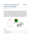
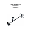
E. Testing Continuity
Tone Generator & Probe
User Manual
1. Slide the toggle switch to the "Cont" position.
2. Connect the test leads to the subject pair.
3. A BRIGHT GREEN light indicates continuity.
Introduction
The Tone Generator is a highly practical network installation
and troubleshooting tool which features a single or multitone signal, two test leads and a 4-conductor modular cable.
The signal emitted by the Tone Generator can be easily traced
by the Probe, even when cables are in a bundle or hidden in a
mess of punch down blocks or wall plates. The Tone
Generator & Probe can be used to verify cable continuity,
identify wiring faults, determine line polarity and voltage in
network (Cat 5 and Coax) and modular telephone lines. The
Probe is equipped with a tone amplifier and an LED indicator
that detects audible frequency tones for accurate tracing and
identification of wires.
Product Profile
2
1
TOGGLE SWITCH
2
RED TEST LEAD
3
BLACK TEST LEAD
4
BATTERY LOW
5
LED DISPLAY
7
1
PROBE
2
SIGNAL
3
LOW BAT.
4
TRACE
Caution:
Do not connect to an active AC or DC circuit in this
mode.
F. Testing Continuity Using Tone
1. Slide the toggle switch to the "Tone" position.
2. Connect the test leads to the subject pair.
3. Using a handset or headset at the remote end,
touch the wire end(s) with the clip lead(s).
4. Reception of tone is an indication of continuity.
Modular Testing
* All above tests are applicable to modular plugs for line 1
only (red & green wires).
3
1
1
2
5
Cont
Off Tone
TONE SELECTING SWITCH
7
4 PIN MODULAR CABLE
3
TONE GENERATOR
BAD
GOOD
4
6
5
BAT.LOW
6
7
5
VOLUME
6
DISPLAY MODE
7
SPEAKER
8
9V BAT.
4
DUAL TONE
SINGLE TONE
6
CABLE
TRACER
8
Tone Generator
Features:
* 2-position switch for single tone or multi-tone signal
* Toggle switch to control 3 modes of operation
* 3-color LED indicator display for telephone line
1
Coax Testing
* To test un-terminated coaxial cables, connect the RED
test lead to the outer shield and the BLACK test lead to
the center conductor, or connect the RED test lead to the
outer shield and the BLACK test lead to the ground.
* To test terminated coaxial cables, connect the RED test
lead to the connector housing and the BLACK test lead
to center pin, or connect the RED test lead to the
connector housing and the BLACK test lead to ground.
6
* One push-button TRACE switch
* One battery low LED indicator
* One amplifier and one LED for signal detection
* One rotary volume level switch
Operation
B. Indicating telephone Line Condition
1. Load the 9V battery.
2. Slide the toggle switch to the "Off" position.
3. Plug the standard 4-pin modular cable into
modular wall jack.
4. LED indicator results:
A. Identifying the polarity of a telephone line
a. BRIGHT GREEN light: indicates a clear line.
b. DIM GREEN light: indicates a busy line.
c. BRIGHT FLASHING RED and GREEN light:
indicates a ringing line.
Cont
1. Load the 9V battery
2. Slide the toggle switch to the
"Off" position
3. Connect the black test lead to ground
4. Connect red test lead to the line you
wish to test
5. LED indicator results:
Off Tone
TONE GENERATOR
BAD
GOOD
BAT.LOW
DUAL TONE
SINGLE TONE
a. GREEN light: indicates normal polarity
b. RED light: indicates reversed polarity
c. YELLOW light: indicates presence of AC
power on the telephone line
Note: If a ground is not available, you may try to switch the
test leads around to different wires within the pair.
The LED indicator will light GREEN when the red test
lead is connected to the ringside of the line and the
black lead is connected to the ground.
3
Note: A DIMLY FLASHING GREEN light will result under
ringing line conditions if the line's polarity is reversed. If the
test is begun prior to an incoming call, the call will be
blocked.
C. Verifying telephone Lines
1. Slide the toggle switch to the "Cont" position.
2. Dial the number of the line you wish to verify.
3. While the line is ringing, connect the red lead to
the ring side of the line, and connect the black
lead to ground.
4. Slide the toggle switch to the "Off" position. The
LED indicator will flicker RED and GREEN
when the test leads are connected to the subject
pair.
5. To verify identification, monitor the line and
switch the test set to "Cont." This will terminate
the call on the subject line.
4
D. Sending a Tone
1. Slide the toggle switch to the "Cont" position
2. Connect the test leads to a pair of wires or attach
one lead to the ground and the other lead to either
side of line, (See Fig. 3).
3.
Cont
Off Tone
TONE GENERATOR
BAD
GOOD
DUAL TONE
SINGLE TONE
C
TR AB
AC LE
ER
BAT.LOW
4. Select either a dual alternating tone or a single
solid tone by positioning the button on the face of
the Tone Generator unit to "DUAL TONE" or
"SINGLE TONE."
5. Select one of the display functions (LED
only/speaker only/LED & speaker together) by
positioning the switch on the side of the Probe to
"L," "S," or "L & S" respectively.
6. Use the Probe to trace the subject wire.
7. Reception of tone will be loudest (amplifier) or
brightest (LED) on the subject wire.
Caution:
Do not connect to an active AC circuit exceeding 24
Volts in this mode.
polarity, continuity and voltage testing
* Black and red testing leads and standard 4-pin modular
cable for individual wire tests or modular jack tests
* Convenient compact size and simple application
Specifications:
* 1 ft. each of red and black test lead
* 1 ft. 4-pin modular cord and plug
* One 3-position toggle switch for operation mode control
* One 3-color LED display for line polarity, continuity
and voltage test
* One 2-position slide switch for tone volume level
selection
* Power: 9V DC battery
Probe
Features:
* Special inductive plastic tip which prevents accidental
shorts (possible with copper-tip tracers) when using
near high voltage devices
* Traces and identifies wires or cable in a bundle or group
without damaging cable insulation
* Adjustable volume level for various work environments
* Both amplifier and LED for loud or dark work
environments
* Can work with any existing tone generator in the market
* Power switch to prevent battery drain
Specifications:
* Pen-style casing
* Special inductive plastic tip
5
2
Remarks
1. Do not touch the tip of Probe to the Active Circuit
contact or line.
2. Remember to adjust the volume rotary switch to reach
an ideal volume level.
3. When the "Battery Low" LED is illuminated, you must
replace the battery to ensure a correct test.
User Manual
Ordering Information:
256711A
256712A
256713A
Tone Generator & Probe
Tone Generator
Probe
Tone Generator & Probe Kit