1
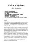
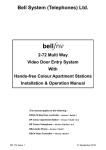
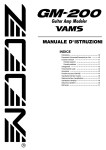
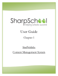
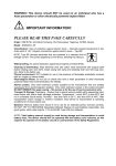
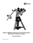
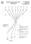
5 November 1998
PD-004 Iss 3
GroupMaster 200+/
PageMaster 200+
User Manual
Bell System (Telephones) Ltd.
Presley Way, Crownhill, Milton Keynes, MK8 0ET
GM200+/PM200+ Software Version 1.4
5 November 1998
PD-004 Iss 3
Contents
General Description . . . . . . . . . . . . . . . . . . . . . . . . . . . . . . . . . . . . . . . . . . . . . . . . . 1
GroupMaster 200+ Software Basic Features . . . . . . . . . . . . . . . . . . . . . . . . . 2
GroupMaster 200+ System Overview . . . . . . . . . . . . . . . . . . . . . . . . . . . . . . . . . . . . 3
Other GroupMaster 200+ Software Modules . . . . . . . . . . . . . . . . . . . . . . . . . . . . . . 4
Printer File logging module . . . . . . . . . . . . . . . . . . . . . . . . . . . . . . . . . . . . . . 4
Radio Pager Module . . . . . . . . . . . . . . . . . . . . . . . . . . . . . . . . . . . . . . . . . . . 4
Requirements . . . . . . . . . . . . . . . . . . . . . . . . . . . . . . . . . . . . . . . . . . . . . . . . . . . . . . 5
Computer . . . . . . . . . . . . . . . . . . . . . . . . . . . . . . . . . . . . . . . . . . . . . . . . . . . . 5
System Design Consideration . . . . . . . . . . . . . . . . . . . . . . . . . . . . . . . . . . . . . . . . . 6
When to use GroupMaster 200+ Software . . . . . . . . . . . . . . . . . . . . . . . . . . 6
Flat numbering Schemes . . . . . . . . . . . . . . . . . . . . . . . . . . . . . . . . . . . . . . . . 7
Choosing a serial card . . . . . . . . . . . . . . . . . . . . . . . . . . . . . . . . . . . . . . . . . . 7
System Integrity . . . . . . . . . . . . . . . . . . . . . . . . . . . . . . . . . . . . . . . . . . . . . . . 8
Installation - Diagram 1 . . . . . . . . . . . . . . . . . . . . . . . . . . . . . . . . . . . . . . . . . . . . . . 10
Installation - Diagram 2 . . . . . . . . . . . . . . . . . . . . . . . . . . . . . . . . . . . . . . . . . . . . . . 11
Connection of RS232/RS422 Cables . . . . . . . . . . . . . . . . . . . . . . . . . . . . . . . . . . . 12
RS232 - PC to C200+ (9 Pin D-Type Connectors) . . . . . . . . . . . . . . . . . . . 12
RS232 - PC to C200+ (9 and 25 Pin D-Type Connector) . . . . . . . . . . . . . . 12
RS422 Connections (C200+ Only) . . . . . . . . . . . . . . . . . . . . . . . . . . . . . . . . 13
RS232 - PC to Multitone Radio Pager System . . . . . . . . . . . . . . . . . . . . . . 13
RS232 - PC to Ascom Radio Pager System . . . . . . . . . . . . . . . . . . . . . . . . 13
-i-
5 November 1998
PD-004 Iss 3
Installation . . . . . . . . . . . . . . . . . . . . . . . . . . . . . . . . . . . . . . . . . . . . . . . . . . . . . . . 14
Installing the Master 200+ Systems . . . . . . . . . . . . . . . . . . . . . . . . . . . . . . . 14
Communication Card . . . . . . . . . . . . . . . . . . . . . . . . . . . . . . . . . . . . . . . . . . 14
C200+ Setup . . . . . . . . . . . . . . . . . . . . . . . . . . . . . . . . . . . . . . . . . . . . . . . . 14
Testing the C200+ Serial Links . . . . . . . . . . . . . . . . . . . . . . . . . . . . . . . . . . 14
Key C200+ . . . . . . . . . . . . . . . . . . . . . . . . . . . . . . . . . . . . . . . . . . . . . . . . . . 15
Fitting The Key C200+ . . . . . . . . . . . . . . . . . . . . . . . . . . . . . . . . . . . . . . . . . 15
Installing GroupMaster 200+ Software . . . . . . . . . . . . . . . . . . . . . . . . . . . . . 16
Setting Up The Software . . . . . . . . . . . . . . . . . . . . . . . . . . . . . . . . . . . . . . . . . . . . 17
GroupMaster 200+ Software Language and Mode . . . . . . . . . . . . . . . . . . . 17
Software Upgrade . . . . . . . . . . . . . . . . . . . . . . . . . . . . . . . . . . . . . . . . . . . . 18
Software Registration . . . . . . . . . . . . . . . . . . . . . . . . . . . . . . . . . . . . . . . . . . 18
Wellcome . . . . . . . . . . . . . . . . . . . . . . . . . . . . . . . . . . . . . . . . . . . . . . . . . . . 19
Adding A New Group . . . . . . . . . . . . . . . . . . . . . . . . . . . . . . . . . . . . . . . . . . 19
Adding A New System . . . . . . . . . . . . . . . . . . . . . . . . . . . . . . . . . . . . . . . . . 21
Getting Help . . . . . . . . . . . . . . . . . . . . . . . . . . . . . . . . . . . . . . . . . . . . . . . . . 22
Password Setup . . . . . . . . . . . . . . . . . . . . . . . . . . . . . . . . . . . . . . . . . . . . . . 22
Password . . . . . . . . . . . . . . . . . . . . . . . . . . . . . . . . . . . . . . . . . . . . . . . . . . . 23
Installing Upgrade Modules . . . . . . . . . . . . . . . . . . . . . . . . . . . . . . . . . . . . . 24
AllCall Amplifier Setup . . . . . . . . . . . . . . . . . . . . . . . . . . . . . . . . . . . . . . . . . 25
The Radio Pager System . . . . . . . . . . . . . . . . . . . . . . . . . . . . . . . . . . . . . . . . . . . . 27
'Radio Pager Setup' Tab . . . . . . . . . . . . . . . . . . . . . . . . . . . . . . . . . . . . . . . 28
'System Zones' Tab . . . . . . . . . . . . . . . . . . . . . . . . . . . . . . . . . . . . . . . . . . . 29
'Alarm Filters' Tab . . . . . . . . . . . . . . . . . . . . . . . . . . . . . . . . . . . . . . . . . . . . 31
'Pagers/Teams' Tab . . . . . . . . . . . . . . . . . . . . . . . . . . . . . . . . . . . . . . . . . . . 33
'Beep Codes' Tab . . . . . . . . . . . . . . . . . . . . . . . . . . . . . . . . . . . . . . . . . . . . 34
'Alarm Templates' Tab . . . . . . . . . . . . . . . . . . . . . . . . . . . . . . . . . . . . . . . . . 35
Basic Operation . . . . . . . . . . . . . . . . . . . . . . . . . . . . . . . . . . . . . . . . . . . . . . . . . . . 36
- ii -
5 November 1998
PD-004 Iss 3
Overview of Demo Systems . . . . . . . . . . . . . . . . . . . . . . . . . . . . . . . . . . . . . 36
The Multi-Group Window . . . . . . . . . . . . . . . . . . . . . . . . . . . . . . . . . . . . . . . 38
Moving to the Single Group Windows . . . . . . . . . . . . . . . . . . . . . . . . . . . . . 39
The Single Group Window . . . . . . . . . . . . . . . . . . . . . . . . . . . . . . . . . . . . . . 39
Moving Systems Between Groups . . . . . . . . . . . . . . . . . . . . . . . . . . . . . . . . 41
Saving System Grouping . . . . . . . . . . . . . . . . . . . . . . . . . . . . . . . . . . . . . . . 42
Changing Radio Pager Assignments . . . . . . . . . . . . . . . . . . . . . . . . . . . . . . 43
Booking Radio Pagers In and Out . . . . . . . . . . . . . . . . . . . . . . . . . . . . . . . . 45
Radio Pager Restart Options . . . . . . . . . . . . . . . . . . . . . . . . . . . . . . . . . . . . 46
Printer/File Logging . . . . . . . . . . . . . . . . . . . . . . . . . . . . . . . . . . . . . . . . . . . 47
Real Time Printing . . . . . . . . . . . . . . . . . . . . . . . . . . . . . . . . . . . . . . . . . . . . 49
Filter Toolbox . . . . . . . . . . . . . . . . . . . . . . . . . . . . . . . . . . . . . . . . . . . . . . . . 50
Page Layout Toolbox . . . . . . . . . . . . . . . . . . . . . . . . . . . . . . . . . . . . . . . . . . 51
Archiving Data . . . . . . . . . . . . . . . . . . . . . . . . . . . . . . . . . . . . . . . . . . . . . . . 53
Icons And Their Meaning . . . . . . . . . . . . . . . . . . . . . . . . . . . . . . . . . . . . . . . 54
- iii -
5 November 1998
PD-004 Iss 3
General Description
The GroupMaster 200+ software packages is a Windows®95 application designed to
support the Master 200+ Nurse Call System. They provide an enhanced operator
interface to one or more Master 200+ systems via a Personal Computer using the serial
communication ports.
Manual Conventions
When PageMaster 200+ mode differs from GroupMaster 200+ mode a note will be
shown.
PageMaster 200+ .......
-1-
5 November 1998
PD-004 Iss 3
GroupMaster 200+ Software Basic Features
System Grouping
Up to eight Master 200+ systems, each of 250 room units, may be combined into one
or more larger system and re-grouped or ungrouped on command. Each group has all
of the facilities of a stand-alone Master 200+ system including full speech. Re-grouping
is performed by a simple drag and drop operation.
In PageMaster 200+ mode only one Master 200+ system can be used and no regrouping is allowed.
Multi-group Overview
The Multi-group screen provides a display of the arrangement of systems within groups
and all Alarm calls and Nurse presences on the entire multi-controller Master
200+system.
Single Group Display
The single group screen gives a detailed display of Alarm Calls and Monitor stations
within the selected group only, with additional details such as time of occurrence.
-2-
5 November 1998
PD-004 Iss 3
GroupMaster 200+ System Overview
-3-
5 November 1998
PD-004 Iss 3
Other GroupMaster 200+ Software Modules
Printer File logging module
All alarm events, speech connections, and monitor station activities are recorded in a
file together with a time log. The user may selectively view or print this log, according
to data range, flat number range, group or system criteria. A real-time printing mode
is also available to allow each of the events to be recorded as they occur.
The print/file logging module is available as standard in PageMaster 200+ mode.
Radio Pager Module
An intelligent radio pager system may be connected to the GroupMaster 200+ PC via
an additional serial communication port.
Several Pager systems are supported
including Ascom and Multitone (please enquire on availability of support for your
preferred pager system).
The GroupMaster 200+ Pager module has an extremely versatile alarm filtering system.
Each pager may be programmed to operate on any permutation of groups, systems,
zones (selected M200+ units) and alarm types. This gives total flexibility in the
assignment of staff.
The pager will display details of the alarm (type and flat number) and sound a variable
bleep according to alarm type, (exact operation depends on the model of the pager
chosen).
The radio pager module is available as standard in PageMaster 200+ mode.
-4-
5 November 1998
PD-004 Iss 3
Requirements
Computer
Personal Computer (IBM compatible)
Windows®95/98
Minimum
Recommended
Processor
486DX2-50MHz
Pentium P100
Hard Disk Space
10Mb
10Mb
Memory
8Mb
16Mb
Display
VGA
SVGA
Serial Card
C
One serial communication port required per C200+ controller
C
RS232 Serial Ports; up to 15m or RS422 Serial Ports; up to 1200m cable
C
Drivers required for Windows®95 operating system
C
16-byte buffer (16550) UART
C
Interrupt sharing for cards of 4 or more ports
Master 200+ System requirements
One C200+ Controller (Issue 2.0 or later) per system, up to a maximum of 8.
In PageMaster 200+ mode only one C200+ Controller can be used.
-5-
5 November 1998
PD-004 Iss 3
System Design Consideration
When to use GroupMaster 200+ Software
Larger Systems
If the total number of flats exceeds 250; Up to eight C200+ controllers, each with up to
250 flats may be combined into one large system of up to 2000 flats
Night-mode switching
If there is a requirement to have several small system, each with dedicated nursing staff
during the day, but one larger system overseen by fewer nurses at night.
The
GroupMaster 200+ software allows up to 8 system to be combined into one or more
groups upon command, enabling a wide variety of work/shift systems to be
accommodated.
Enhanced Display of Information
Whether you have a single system or as many as eight, the PC, running the
GroupMaster 200+ software, provides a means of over-viewing the whole operation
from a PC. All alarm calls can be viewed, Nurse presences monitored, and response
times to calls observed.
Printer/File Logging
If there is a requirement for the logging of system activity. The GroupMaster 200+
software can log system activity both directly to a printer or to a computer file for later
retrieval and printing.
Radio Pagers
If radio pagers are required to inform staff of alarm calls. The GroupMaster 200+
software has a versatile radio pagers system that is separate from the system grouping
allowing for almost any pager scheme imaginable.
-6-
5 November 1998
PD-004 Iss 3
When to use PageMaster 200+ Mode
The PageMaster 200+ is supplied with the printer/file logging and radio pager software
modules supplied, hence, if no system grouping is required (PageMaster 200+ is limited
to one C200+ controller) a significant saving can be made.
Diferences between GroupMaster 200+ and PageMaster 200+
The GroupMaster 200+ and PageMaster 200+ modes are very similar in most respects.
The differences are listed below:
GroupMaster 200+
PageMaster 200+
Maximum Groups
8
1
Maximum Systems
8
1
Radio Pager Module
Upgrade module
Included as standard
Printer/File Logging
Upgrade module
Included as standard
Flat numbering Schemes
Each C200+ controller can be programmed with 4 character alphanumeric flat numbers
(see Master 200+ Installation manual). On a GroupMaster 200+ (multi-controller)
system it is important that a flat numbering system is chosen for the whole scheme,
which is easily understood, and avoids duplication. In some cases this is inherent in the
original design of the scheme. A problem arises when each system, which may
represent a wing or blocks, has overlapping flat numbers (eg East Wing 1 - 40 and
West Wing 1 - 40). One solution would be to append a system number or letter to the
flat number (eg 101 - 140 & 201 - 240 or E1 - E40 & W1 - W40)
Choosing a serial card
Each C200+ system requires a serial communication port on the PC. These ports may
-7-
5 November 1998
PD-004 Iss 3
be RS232 or RS422 compatible, however, the cable restrictions of RS232 (15M) should
be noted.
Any Serial card which uses the 16550 UART and is supplied with Windows®drivers
should in theory be suitable, but compatibility cannot be guaranteed.
For systems of four C200+s and above, four or eight port cards which use interrupt
sharing are advised, to avoid exceeding your PC’s interrupt capability.
The following Cards have been tested with the GroupMaster 200+ software and are
therefore recommended:
C
Avantech PCL - 746+
(4 off RS232/RS422 Ports)
System Integrity
A Master 200+ system may be regarded as a safety critical system, in that peoples lives
may depend upon an alarm call being correctly and promptly received by Nursing staff;
Windows®95 is not a protected operating systems, which means that if one application
(such as a wordprocessor) hangs (stops running) it may bring down all other
applications.
The GroupMaster 200+ software has been carefully designed to allow for Windows
crashes, but the consequences for the operation of the Master 200+ system must be
understood by the user.
In the worst case, if the Windows®operating system totally hangs, the individual
C200+controllers will automatically ungroup and continue to operate as individual
systems, without the loss of any alarm calls.
It is important therefore that the alarm reporting system takes this possibility into
account. Our recommendation is that for each C200+ controller an alarm output is
connected to either a bank of lamps or audible sounder placed in all staff locations, that
is, in addition to any primary system such as radio pagers which are to be used on the
site.
-8-
5 November 1998
PD-004 Iss 3
Any member of staff who is authorised to operate the GroupMaster 200+ PC should be
fully appraised of this situation, and of the importance of restarting the PC as soon as
possible. It is also important to ensure that the system grouping is correctly reestablished after a re-start (see ‘Save System Grouping’ page 42).
-9-
5 November 1998
PD-004 Iss 3
Installation - Diagram 1
- 10 -
5 November 1998
PD-004 Iss 3
Installation - Diagram 2
- 11 -
5 November 1998
PD-004 Iss 3
Connection of RS232/RS422 Cables
RS232 - PC to C200+ (9 Pin D-Type Connectors)
RS232 - PC to C200+ (9 and 25 Pin D-Type Connector)
- 12 -
5 November 1998
PD-004 Iss 3
RS422 Connections (C200+ Only)
RS232 - PC to Multitone Radio Pager System
RS232 - PC to Ascom Radio Pager System
- 13 -
5 November 1998
PD-004 Iss 3
Installation
Installing the Master 200+ Systems
Before installing and the GroupMaster 200+ software install and fully commission all of
the Master 200+ systems.
Communication Card
Install the communication cards and drivers in the PC, in accordance with the
manufacturers instructions.
C200+ Setup
To setup the C200+ controllers refer to the Master 200+ Installation Manual.
We strongly recommend that the following guidelines are followed: to avoid operator
confusion.
Uniform setup across systems
The following settings should be the same on each system; Master access code, Alarm
cancellation, Alarm Regeneration, Alarm tones, Alarm Priority, Alarm outputs
Use an overall flat numbering scheme
Ensure that no two flats have the same number (possibly use letters for differentiation)
Delete all unused flat numbers
This minimizes system resources use by the GroupMaster 200+ software.
Testing the C200+ Serial Links
If the C200+ setup is performed from the PC that GroupMaster 200+ software will be
installed on, this will test the serial link(s).
- 14 -
5 November 1998
PD-004 Iss 3
Key C200+
The GroupMaster 200+ software is supplied with a Key micro processor which must be
installed in any one of the C200+ controllers. This must be performed by a qualified
engineer and electrostatic precautions must be followed.
The Key C200+ is required to gain access to all the GroupMaster 200+ functions.
Make a note of the serial port to which the Key C200+ is attached and ensure it is
connected to the PC and that the Master 200+ system is switched on and running.
Fitting The Key C200+
This can be done by :1.
Switch off the system (check there is no power on the C200+ terminals 1 and 2)
2.
Touch the earth stud of the C200+ box, to discharge any static electricity
3.
Remove the current IC (IC5) using a small screw driver.
4.
Carefully remove the new Key C200+ from its antistatic box and insert it into the
vacant socket making sure that the polarity (shown below) is correct
5.
Switch on the power and check the system is operating properly.
Note C200+ settings are stored on EEPROM and are not changed when installing a
Key C200+
- 15 -
5 November 1998
PD-004 Iss 3
Installing GroupMaster 200+ Software
The latest version of GroupMaster 200+ Software can be downloaded from the world
wide web (www.bellsystem.co.uk)
Removing the Previous Version of GM200+ Software
Before installing a new version of software, it is generally a good idea to remove the old
version (with GroupMaster 200+ your settings will remain in tact), this is done by:
1.
Click the Start button in Windows®95.
2.
Point to Settings, and then click Control Panel.
3.
Double-click Add/Remove Programs highlight GM200+ in the list then click
Add/Remove.
Windows®95 Installation
1.
Click the Start button in Windows®95.
2.
Point to Settings, and then click Control Panel.
3.
Double-click Add/Remove Programs then click Install.
- 16 -
5 November 1998
PD-004 Iss 3
Setting Up The Software
Run the GroupMaster 200+ software by:C
In Windows®95 click the Start button, point to Programs and then select Gm200
(you may wish GroupMaster 200+ software to start automatically when your
computer is switched on OR install a shortcut on your desktop; consult your
Windows®95 documentation for details of how to do this)
GroupMaster 200+ Software Language and Mode
After the software is started for the first time you will be prompted for the Language and
mode to use.
You can change the language or the software type, at a later date, from the File menu
select Settings then select Language or Software Type.
- 17 -
5 November 1998
PD-004 Iss 3
Software Upgrade
If a previous version of GroupMaster 200+ software has been detected on your
computer you will be asked if you wish to remove all previous settings, normally you
should answer no.
Software Registration
You will be asked to register the software. Type in your name and company in the
boxes provided then select the COM port that your Key C200+ is installed on (or select
Demo System if a Key C200+ is not available).
- 18 -
5 November 1998
PD-004 Iss 3
Wellcome
When the software is started for the first time there will be no Groups or Systems
installed. The following dialogue appears.
You must now install some groups and systems before using the software. Either use
the ‘Install a Group’ button on the above dialogue or follow the procedure on ‘Adding
a New Group’.
Note. The password is initially set to 1234.
Adding A New Group
To install a new group, from the File menu select New then Group. The following
dialogue will then appear:
- 19 -
5 November 1998
PD-004 Iss 3
New Group Name
This is the name used throughout the software to refer to this group. If possible use a
name that describes this group.
e.g.
Ground Floor, Queen Mary Wing, Night Group etc.
Done Button
Closes this dialogue.
Add Button
Installs the group into the GroupMaster 200+ software.
Add New System Button
Goes to the Add New System dialogue.
In PageMaster 200+ mode only one Group can be installed.
- 20 -
5 November 1998
PD-004 Iss 3
Adding A New System
To install a new system, from the File menu select New then System. The following
dialogue will then appear:
System Name
This is the name used throughout the software to refer to this system. If possible use
a name that describes this system.
e.g.
Ground Floor, Queen Anne Ward etc.
Initial Group
This selection box lists all the groups currently installed. Select the group that the new
system should start in.
COM Port Selection
This selection box lists all the currently available COM ports. Select the COM port
which is connected to this system’s C200+ controller.
Done Button
Closes this dialogue.
- 21 -
5 November 1998
PD-004 Iss 3
Add Button
Uploads the current settings of the C200+ connected on the selected COM port and
installs the system into the GroupMaster 200+ software.
Note. To add a system to the GroupMaster 200+ software the C200+ controller must
be present and operating at the time.
In PageMaster 200+ mode only one System can be installed.
Getting Help
The GroupMaster 200+ software provide an extensive online help system that can be
accessed from the menu, by pressing [F1] or help button on many dialogues.
Context Sensitive Help
Context sensitive help gives you the most appropriate help topic simply by pressing
[F1].
Password Setup
A password may be required to gain access to many GroupMaster 200+ functions. The
password setup dialogue allows for adding, removing and altering a password.
Select File on the main menu, then Setting, then Password and the following dialogue
will appear.
Before you can change any password settings you must first enter the current
password.
- 22 -
5 November 1998
PD-004 Iss 3
You may then enter a new password and select which functions are to be protected.
In the above example a password will be required to add and remove groups or
systems. However, no password is required to move systems between groups.
Note. The password options will vary dependent upon which software modules are
installed.
Password
For many functions within the GroupMaster 200+ software the password may be
required.
Enter the password and then press OK or Enter.
Password Required Next Time
If you remove the tick in the 'Password required next time' box you will not be required
to enter the password in the future. You can reinstate the password at a later date with
Password Setting.
Note. Before you can turn off the password requirement you must have entered the
password.
- 23 -
5 November 1998
PD-004 Iss 3
Installing Upgrade Modules
Additional software modules can be added, this may require set of upgrade disks, and
an access code to enable the module.
Entering an Access Code
To enter an access code for a software module, select File on the main menu the
Settings and then Installed Modules, finally select the check boxes for the modules you
wish to install.
- 24 -
5 November 1998
PD-004 Iss 3
AllCall Amplifier Setup
To access the AllCall amplifier setup dialogue, select File, then Settings and finally
AllCall Amplifier Options.... The following dialogue will appear:
AllCall Amplifier Components
A200+, This is the amplifier unit, generally each system will have an A200+ connected
to it, (there are some exceptions, see the AllCall Amplifier Installation Manual)
KS200+, One or more KS200+ units can be connected to the A200+. The unit has two
key switches and a microphone; one key switch will operate the emergency alarm, the
other is used to make a general announcement with the microphone.
Operating this key switch will put the system into emergency alarm mode.
M200+ room units will sound an alarm tone.
Operating this key switch will put the system into general announcement
mode; the operator can make an announcement to M200+ room units.
- 25 -
5 November 1998
PD-004 Iss 3
GroupMaster Operation
This icon indicates that the system has an AllCall amplifier generating
an emergency tone (or general announcement); the system cannot be
moved.
When a KS200+ is activated on a system, the system can behave in one of two ways:
Operate all M200+'s on the entire system. With this option selected, all M200+’s will
generate an emergency tone or general announcement regardless of system grouping,
this selection should be used if the KS200+ is intended to be used for evacuation tones
or emergency announcements, as no system regrouping is require before making the
emergency call to all M200+’s.
Operate the M200+'s on active group only. With this option selected only M200+’s
located in the same group as the calling KS200+ will generate an emergency tone or
general announcement.
In this mode only one group can have an active KS200+ at any one time; this may
require systems to be regrouped before an evacuation tone can be made.
Note Because of the nature of emergency calls, when the KS200+ is activated all calls
are suspended.
Systems Without AllCall Amplifiers
If any system is not required to generate an emergency tone or a general
announcement it can be disabled (reducing the need for AllCall Amplifiers).
- 26 -
5 November 1998
PD-004 Iss 3
The Radio Pager System
To setup the radio pager system:
Follow the steps below:
C
Ensure all of the C200+ controllers on the system have been correctly installed
and setup.
N.B.
To ensure that the GroupMaster 200+ software runs at optimum
efficiency it is important that there are no redundant flat numbers
programmed into the system. To check the flat numbers, select File
then Properties then the system; on the dialogue that appears click the
'Flats' tab; all unused addresses should be blank. To correct any
problems run the C200+ setup software.
C
Activate the radio pager software module (see page 24).
C
To access the radio pager setup dialogue, select File, then Settings and finally
select Radio Pager Setup.
C
Select the type of radio pager system, using the 'Pager Setup Tab' (see page
28).
C
Define zones (a collection of M200+ room units), using the 'System Zones Tab'
(see page 29).
C
Create alarm filters (a combination of zones and alarm types), using the 'Alarm
Filters Tab' (see page 31).
C
Assign pagers to the alarm filters that you have created, using the
'Pagers/Teams Tab' (see page 33).
C
Specify the beep code and alarm message for each alarm type, using the 'Beep
Codes Tab' and 'Alarm Templates Tab' (see pages 34, 35).
Note. The radio pager software module must be installed and activated to setup and
use radio pagers.
- 27 -
5 November 1998
PD-004 Iss 3
'Radio Pager Setup' Tab
Pager system
Select the pager system in use, select from the list.
Com Port
To specify the Com port that your pager system is connected to, select from the list.
Call Default Pagers
Set the time before the default pagers are called , (if the call is left unanswered).
Recall Pagers
Set the time (in minutes) before a pager is recalled, (if the call is left unanswered).
e.g.
If the default pager time is set to 4 minutes and the recall pagers time is set to
2 minutes. The associated pagers will trigger immediately and every 2 minutes
- 28 -
5 November 1998
PD-004 Iss 3
there after. The default pager will trigger after 4 minutes and every 4 minutes
thereafter.
'System Zones' Tab
For each system (C200+) that has been installed into the GroupMaster 200+ software
there will be a system tab. When the system tab is selected the dialogue will display
a representation of eight zones; all of the available M200+ units will be listed (initially
in zone 1).
The dialogue enables the system(s) to be subdivided into eight zones. A radio pager
can subsequently be associated with one or more of these zones (as opposed to the
whole system).
e.g.
A single system with 20 M200+ units and two pagers. Pager 1 should activate
when units 1 to 10 are in alarm and pager 2 when units 11 to 20.
Units 1 to 10 should be placed in zone 1 and units 11 to 20 in zone 2
- 29 -
5 November 1998
PD-004 Iss 3
Changing Zone Names
Move the mouse pointer over the current name and click, you can now change the
name. Try to use meaningful names if possible e.g. Ward 1, Hall 2, Top Floor.
Moving M200+ units Between Zones
Highlight the M200+ units that you wish to move by clicking on them (use [Ctrl] or
[Shift] to make multiple selections) . Click the
then select the destination zone from the list.
- 30 -
button or the right mouse button and
5 November 1998
PD-004 Iss 3
'Alarm Filters' Tab
An alarm filter is a combination of zones qualified by alarm types.
E.G. West Wing - Floor 1 and East Wing - Floor 1, Urgent Help only.
(System 1 - Zone 1 and System 3 - Zone 1, Urgent Help only.)
An alarm filter should be defined for each combination of zones and alarm types which
may be required to activate a radio pager(s).
- 31 -
5 November 1998
PD-004 Iss 3
Creating a New Alarm Filter
Click the New button and enter the new name. Try to use meaningful names if possible
e.g. Urgent W1 & E1
The 'Excluded Zones' list will now contain all of the zones that have been previously
defined.
Highlight the zone(s) which are required for this alarm filter and click the Add button to
transfer them to the 'Included Zones' list.
To qualify the alarm filter use the 'Alarm Type' check boxes as required.
Editing an Existing Alarm Filter
Select the alarm filter to edit by selecting it from the 'Alarm Filter Name List' then
change the details on the screen.
- 32 -
5 November 1998
PD-004 Iss 3
'Pagers/Teams' Tab
This tab allows you to enter/view details of available radio pagers.
Adding A New Radio Pager
C
Click the Add Button
C
Enter the new pager details:
C
Name (e.g. Joe Bloggs),
C
Pager address (number),
C
Alarm filter that will trigger this pager,
C
Specify if the radio pager is a single user or team address.
C
Specify whether this pager is to be a default pager.
View Pager Details
Highlight the pager in the 'Pagers and Teams' list to view its details.
Note. Details vary dependant upon the pager system in use.
- 33 -
5 November 1998
PD-004 Iss 3
'Beep Codes' Tab
Use this tab to set up the beep codes for each alarm type (the beep code list will vary
depending on the type of pager system in use).
Note. Its is advisable to choose only 2 or 3 different beep codes to avoid operator
confusion.
- 34 -
5 November 1998
PD-004 Iss 3
'Alarm Templates' Tab
Use this tab to set up the message for each alarm type. The XXXX represents the flat
number and cannot be deleted it can however be moved to the beginning of the
message. Message can be up to 16 characters in length.
Note. It is advisable to use messages similar to the messages used by the M200+
system.
- 35 -
5 November 1998
PD-004 Iss 3
Basic Operation
Overview of Demo Systems
In many instances it may be beneficial to install demo system initially so that a complete
understanding of the software and its operation can be gained prior to setting up the
system. Demo systems are also used for training, and for sales purposes.
Because of the powerful nature of demo systems (they can place alarm calls on the
system) a limit of 30 minutes has been imposed, after which the software shuts down.
A Key C200+ controller is not required for a demo system.
To turn demo systems on/off, from the File menu select Settings and then Demo
Systems. The GroupMaster 200+ software will then have to be restarted for this change
to take effect.
Note. To turn demo systems off you will first have to delete all demo systems.
Accessing Demo Alarm Generator
To view the demo system dialogue select View from the main menu, then View Alarm
Generator, and finally the system to view. The following dialogue will then appear.
- 36 -
5 November 1998
PD-004 Iss 3
Generating an Alarm
Select the unit number from the list box for the alarm required then press one of the
alarm buttons on the room unit graphic. Repeat as required (up to a maximum of 4
standard alarms and 2 priority alarms).
Cancelling an Alarm
C
Highlight the alarm in the current alarms list box and press [Delete].
OR
C
Connect and cancel on a Master room unit.
Generating Random Alarms
To generate a series of alarms automatically and with random addresses/types. Click
the option box to enable random alarms then select the time period and alarm filters
as required.
- 37 -
5 November 1998
PD-004 Iss 3
The Multi-Group Window
The multi-group window is an overview of the entire system.
Multi-Group Window
The multi-group window is divided into group panels. The layout and appearance of
this window is dependent upon GroupMaster 200+ settings.
In the example above there are five groups. Three groups contain no systems (and are
shown minimized on the right).
The remaining two groups:Group 1 contains three systems, with one alarm call and one monitor station.
Group 2 contains two systems, with 2 alarm calls (one of which is connected) and one
monitor station.
In PageMaster 200+ mode only one Group and one System will be seen.
- 38 -
5 November 1998
PD-004 Iss 3
Moving to the Single Group Windows
There are a number of ways of moving from the multi-group window to a single group
window.
C
Click the title bar in the group panel of the group you wish to view.
C
From the View menu select View Single Group and select the group to view
C
Double click an alarm/call in the group to view
The Single Group Window
The single group window is divided into four areas.
M200+ Emulation
On the left is a representation of the M200+ keypad and LCD display. The LCD display
shows the group status in the same manner as a Monitor M200+ unit.
- 39 -
5 November 1998
PD-004 Iss 3
Alarm Status List
A list of all the alarms and calls in this group.
Monitor List
A list of all monitor stations in this group.
Button Bar
At the bottom of the window is a group button bar allowing fast access to all other
groups. The button on the right returns to the multi-group window.
Note. You can alter the format of the information displayed in the alarm and monitor
lists. Try the Screen Font Size (under the File Menu) and System Name, 24 Hour
Clock (under the View menu).
- 40 -
5 November 1998
PD-004 Iss 3
Moving Systems Between Groups
To Move a System between Groups
1.
Move the mouse pointer over the system to be moved (the mouse icon changes
from an arrow to a hand).
2.
Press and hold the left mouse button.
3.
Drag the system onto the target group panel and release the left mouse button.
You may then be required to enter a password dependent upon GroupMaster 200+
options and asked to confirm the move.
The system will then relocate to the target group moving any alarms and monitor
stations as well.
Indicates a locked system that cannot be moved (normally due to a connected
call).
In PageMaster 200+ mode Systems cannot be moved between groups.
- 41 -
5 November 1998
PD-004 Iss 3
Saving System Grouping
The GroupMaster 200+ software provides two settings for how the system should treat
system grouping when the software is restarted:
1.
Save the system grouping on exit (the exit system grouping will be the start up
grouping)
2.
Fixed grouping (the system grouping will start as defined when the systems were
initially added or the last save of current grouping).
To access the save system grouping dialogue select File on the main menu, then
Setting, then Save System Groupings and the following dialogue will appear.
The system grouping can be saved when the software is shut down (as above). This
means that when GroupMaster 200+ is restarted the systems will start in the same
groups.
If, however, save system grouping on exit is not ticked the systems will start in the
groups defined by the last ‘Save Current Groupings’ save.
Not available in PageMaster 200+ mode.
- 42 -
5 November 1998
PD-004 Iss 3
Changing Radio Pager Assignments
Radio pagers are easily reconfigured to trigger from a different set of M200+ units
(alarm filter). From the View Menu select View Radio Pager Configuration. The
following dialogue will then appear.
For each alarm filter that has been defined for your system a list of associated radio
pagers will be displayed. In the above example there are four filters (if there are more
than six alarm filters a scroll bar will appear).
Pager configurations make it easy to swap between a number of radio pager
assignments (for day and night time use etc.) and also to temporarily reassign a radio
pager.
- 43 -
5 November 1998
PD-004 Iss 3
Reassigning a Radio Pager to a Different Alarm Filter
Highlight the radio pager(s) that you want to reassign (use [Ctrl] or [Shift] to make
multiple selections) and then click on the
button or press the right mouse button.
Select the new alarm filter from the list that appears; the pager(s) will then be sent to
the new alarm filter.
Alarm Filter Summary
Each of the alarm filters listed also has an alarm filter summary, click on the
button
or press the right mouse button, from the list that appears select 'Filter Summary'
Saving Radio Pager Configurations
After the radio pagers have been setup using the above dialogue you may save this
configuration by pressing the [Save] or [Save As] button. Choose a meaningful name
for this configuration e.g. Day Shift.
Recalling Radio Pager Configurations
Select the configuration required from the 'Configuration' list. Press OK to close the
dialogue
- 44 -
5 November 1998
PD-004 Iss 3
Booking Radio Pagers In and Out
Radio pagers can be booked 'In' to inform the GroupMaster 200+ software that the
pager is in use; OR booked 'Out' when the member of staff (who owns the pager) is
unavailable. From the View Menu select View Radio Pager Configuration finally click
the 'Pagers In/Out' tab.
Not all pager systems support this feature.
To book pager in or out select the required pager(s) then press [<< - In] or [Out - >>]
(use [Ctrl] or [Shift] to make multiple selections).
Note. Radio pagers in the 'absent pagers' list, labeled [On Charge], are currently being
charged and cannot be booked in.
- 45 -
5 November 1998
PD-004 Iss 3
Radio Pager Restart Options
When GroupMaster 200+ software is started, the radio pagers can be configured in one
of two ways:
C
Always with the same configuration. Select the 'Always restart with:' option and
then choose from the list.
C
Restart with the last configuration used.
Select the 'Restart using last
configuration:' option.
From the View menu select View Radio Pager Configuration finally click the 'Settings'
tab.
- 46 -
5 November 1998
PD-004 Iss 3
Printer/File Logging
Before the printer/file logging options can be used the software module must be
activated (see page 24).
File Logging
While the printer/file log is enabled all events are written to a file (GM2Event.Log) this
information can be selectively viewed or printed as required.
Viewing and Printing a Report
Within the multi-group window select from the View menu, View/Print Report (a
password may be required).
The 'view/print report' window will appear; this can be used to view data from three
sources:
Current Log
This is the file into which all events are initially stored.
From the View menu select Current Log.
- 47 -
5 November 1998
Archive Log
PD-004 Iss 3
An archive file contains old events that have
previously been transferred from the current log.
From the View menu select Archive Log, finally
select the archive file required (see page 53).
Real Time Log
This is a view of an incomplete page of the events which have not yet
been printed.
From the View menu select Real Time Log. (This
option is only available if 'Real Time Printing' is on)
Report Layout
To select the criteria for the report (types of events, date range etc.) use the Filter
ToolBox (see page 50).
To setup headers, footers, font and margins use the Page Layout Toolbox (see page
51).
Tabs are set using the 'tab strip' (located below the button bar). The tabs may be
dragged into the required position.
Print/Print Setup
Use the Print setup option (File menu) to select the printer, paper size and paper
orientation.
Use the Print option (File menu) to print a report.
Note. Page layout and printer settings are stored separately for report creation and for
real time printing.
- 48 -
5 November 1998
PD-004 Iss 3
Real Time Printing
Real Time Printing records events as they occur to produce a hard copy. A full page of
events are collected before being printed.
To enabled/disabled Real Time Printing from the multi-group window; select Real Time
Printing from the File menu (a password may be required).
Viewing/Printing Incomplete Pages
From the multi-group window select View, then select View/Print Report (a password
may be required); the 'view/print report' window will then appear.
From the View menu select Real Time Log
Page Layout
Set the view/print report window to 'Real Time Log' (From the View menu select Real
Time Log)
To select the criteria for the report (types of events) use the Filter ToolBox (see page
50).
To setup headers, footers, font and margins use the Page Layout Toolbox (see page
51).
Tabs can be set using the 'tab strip' (located below the button bar). The tabs may be
dragged into the required position.
Printer Setup
Set the view/print report window to 'Real Time Log' (From the View menu select Real
Time Log)
Select the printer, paper size and paper orientation from the print setup dialogue (File
menu, Print Setup).
Note. Page layout and printer settings are stored separately for real time printing and
for report creation.
- 49 -
5 November 1998
PD-004 Iss 3
Filter Toolbox
The 'Filter Toolbox' is used to select which
events are to be include in a report. To
access the 'Filter Toolbox'; from the Tools
menu select Filter, or use the
button on
the button bar.
'Dates' Tab
Select the start and end dates of events to include in the report (Default - all dates).
'Groups & Systems' Tab
Only events from highlighted Groups and Systems will be included in the report (use
[Ctrl] or [Shift] to make multiple selections).
'Events' Tab
Tick the option boxes for the event types required in the report. These functions are
duplicated on the button bar.
Note. The 'Dates' and 'Group & Systems' tabs are not available if the 'Real Time Log'
view is selected.
- 50 -
5 November 1998
PD-004 Iss 3
Page Layout Toolbox
To access the 'Page Layout Toolbox'; from the Tools menu select Page Layout, or use
the
button on the button bar.
'Header' and 'Footer' Tabs
These two tabs are used to define the header and footer information to use on each
page of a report. Type the text required for the left, centre and right position on the
header or footer.
Three special codes are available:
&p
Page number.
e.g. 'Page &p' would produce 'Page 1, Page 2, ....'
&d
Date (format as defined on the 'Date and Time' tab)
&t
Time (format as defined on the 'Date and Time' tab)
- 51 -
5 November 1998
PD-004 Iss 3
'Date and Time' Tab
This tab is used to select the format in which the time and date is printed on a report.
There are several pre-defined formats available or a user defined format can be created
(see on line help).
'Margins' Tab
Use this tab to set the margins for the page measured in mm; all four margins are
identical.
'Font' Tab
Use the 'Font' tab to select the text font, font size and font style for a report.
The Button Bar
- 52 -
5 November 1998
PD-004 Iss 3
Archiving Data
While the 'Printer/File Logging' software module is activated all events are automatically
stored to a file. After a period of time, depending on the level of system activity, this file
may become unmanageable in size. To maintain the performance of report printing we
recommend that old events are archived regularly (these can still be accessed later if
required).
To archive events; from the File menu select Create Archive; select the date range of
events to be archived (this will always start with the earliest event); finally select a file
name for the archive file.
Note. Like all data files it is advisable to backup any archive files and the file log
(GM2Event.Log) at regular intervals.
- 53 -
5 November 1998
PD-004 Iss 3
Icons And Their Meaning
This is the basic system icon. This system can be regrouped.
This is a locked system icon indicating that a call is currently connected.
The system cannot be regrouped until the call has finished.
This system has an AllCall amplifier generating an emergency tone (or
general announcement). The system cannot be moved.
This system is currently under control of a D200+ (auto dialler) and all
calls within this group will be routed to the central control station.
This is an unavailable system. The system has ceased communicating
with the GroupMaster 200+ software.
This is a system in test mode.
This is a Demo system used for training and sales.
This is an M200+ unit with an alarm call.
This is a connected M200+ unit (Speech is active).
This is a connected M200+ unit in privacy mode, the resident has pressed
the grey privacy button.
- 54 -