1
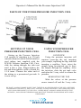
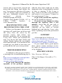
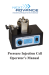
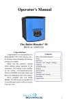
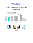
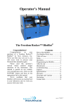
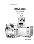
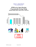
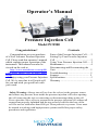
Operator’s Manual
Pressure Injection Cell
Model PC8500
Congratulations!
Congratulations on your purchase
of a Next Advance Pressure Injection
Cell. Please read this operator’s manual
which explains proper operation of the
instrument. This manual can also be
viewed on the web at
http://www.nextadvance.com/publi
c/file/Press_Inject_Cell_PC8500_manu
al.pdf
Enjoy using your Pressure Injection
Cell. We’re sure that it will work well
for you and wish you good luck with
your work.
Contents
Parts of the Pressure Injection Cell...... 2
Setting Up Your Pressure Injection
Cell....................................................... 2
Using Your Pressure Injection Cell...... 2
Maintenance......................................... 4
Disconnecting and Reconnecting the
Unit…………………………….……. 5
Troubleshooting .................................. 5
Support................................................ 5
Specifications....................................... 5
Warranty ............................................. 6
Safety Warning: Always turn off (or close the valves) at the pressure source
and release any pressure from inside the pressure injection cell before opening
the cell (removing the top) or connecting or disconnecting tubing to the cell.
Never open the valves or try to pressurize the pressure injection cell without all
connections properly tightened and the top securely bolted to the base of the
cell. Do not use with more than 8500 psi. Wear protective eyewear. Users must
be trained in working with high pressure systems and follow proper safety
procedures and regulations.
Operator’s Manual for the Pressure Injection Cell
PARTS OF THE PC8500 PRESSURE INJECTION CELL
SETTING UP YOUR
PRESSURE INJECTION CELL
USING YOUR PRESSURE
INJECTION CELL
Setting up the Pressure Injection
Cell consists of attaching it to 1/8 inch
(outside diameter) thick walled stainless
steel tubing (not supplied with the
PC8500 Pressure Injection Cell). First,
slide the tubing through the inlet nut
until it hits a stop. Finger-tighten the
nut and then tighten it with a wrench for
1-1/4 turns. Connect the other end of
the tubing to a pressurized gas tank. It
is now set up.
OVERVIEW
Using the pressure injection cell
requires removing the top, inserting
your sample, replacing the top, and then
inserting a capillary. Next, inject the
sample using pressurized gas to force
the sample through the capillary. After
the injection, close the gas tank valve
and open the 3-way valve to release the
pressure.
REMOVING THE TOP
With the valves at the pressure
source turned off and the 3-way valve
BE SAFE. ALWAYS MAKE SURE THAT THERE IS NO PRESSURE IN THE CELL BEFORE
LOOSENING THE BOLTS, AND THAT THE BOLTS ARE SECURELY FASTENED BEFORE
APPLYING PRESSURE TO THE CELL. USERS MUST ALWAYS WEAR PROTECTIVE
APPAREL, INCLUDING EYEWEAR AND MUST BE TRAINED IN WORKING WITH HIGH
PRESSURE.
2
Operator’s Manual for the Pressure Injection Cell
opened to release any pressure inside
the cell, loosen the three bolts securing
the top, 2 turns each. Rotate the top
counterclockwise by 60 degrees so that
the hexagonal sides are even. Then lift
off the top.
INSERTING THE SAMPLE
Place the sample tube in the main
hole of the base. The tube should not be
capped. If the cap is hinged, you must
cut off the hinge (with scissors). There
is a recess in the top so the tube can
protrude from the base, but a hinged
cap will not fit in the recess.
The sample tube protrudes from the base for
easy insertion and removal.
REPLACING THE TOP
Confirm that the black O-ring is
seated in its groove. Slip the top onto
the base, rotate the top 60 degrees
clockwise, and then tighten the three
bolts using a hex wrench.
Use a hex wrench to tighten the three bolts.
INSERTING A CAPILLARY
Loosen the nut covering the white
ferrule using a wrench. Slide the
capillary through the small hole in the
ferrule, until it reaches the bottom of
the sample tube. Tighten the nut,
thereby squeezing the ferrule tightly
around the capillary.
To remove the capillary, loosen the
nut and slide the capillary out.
INJECTING A SAMPLE
First point the knob on the 3-way
valve towards the stainless steel tubing
connected to the gas tank. Then, while
looking away from the gas tank gages
and with your hand covering them (in
case they explode when the pressure is
turned on) open the gas tank valve.
Adjust the pressure regulator to the
desired pressure.
When the injection is finished,
close the gas tank valve. Then turn the
BE SAFE. ALWAYS MAKE SURE THAT THERE IS NO PRESSURE IN THE CELL BEFORE
LOOSENING THE BOLTS, AND THAT THE BOLTS ARE SECURELY FASTENED BEFORE
APPLYING PRESSURE TO THE CELL. USERS MUST ALWAYS WEAR PROTECTIVE
APPAREL, INCLUDING EYEWEAR AND MUST BE TRAINED IN WORKING WITH HIGH
PRESSURE.
3
Operator’s Manual for the Pressure Injection Cell
knob on the 3-way valve so that it
points toward the vent.
This depressurizes the injection cell.
Now you can loosen the nut over the
ferrule and remove the capillary, loosen
the three bolts, remove the top, and
remove your sample tube.
Photograph of a 1 ml tube with a hinged cap
(left) and of a 1 ml tube with the hinge cut off
and the bottom placed in an adapter
composed of soft tubing (right).
Use a wrench to tighten the nut, forcing the
ferrule to squeeze tightly around the capillary.
USE OF ADAPTER FOR 1 ML
TUBES
We supply one adapter with the
pressure injection cell so that 1 ml tubes
are as easy to work with as taller tubes.
The central hole in the base of the
pressure injection cell is sized so that
1.5 or 2 ml sample tubes will protrude
above the surface, making placement
and retrieval easy. A (surprisingly)
simple adapter will enable 1 ml
microcentrifuge tubes to protrude, too.
The adapter is a piece of soft tubing
(1/4 inch inside diameter, 3/8 inch
outside diameter). As with any tube
with a hinged cap, first cut off the hinge
so that the top of the tube will fit in the
recess in the top of the pressure
injection cell. Next, slide the adapter
onto the bottom of the 1 ml sample
tube, as shown in the figure below.
MAINTENANCE
Periodically, the Teflon ferrule
should be replaced. Simply remove the
nut covering the ferrule, remove the
BE SAFE. ALWAYS MAKE SURE THAT THERE IS NO PRESSURE IN THE CELL BEFORE
LOOSENING THE BOLTS, AND THAT THE BOLTS ARE SECURELY FASTENED BEFORE
APPLYING PRESSURE TO THE CELL. USERS MUST ALWAYS WEAR PROTECTIVE
APPAREL, INCLUDING EYEWEAR AND MUST BE TRAINED IN WORKING WITH HIGH
PRESSURE.
4
Operator’s Manual for the Pressure Injection Cell
ferrule, place a new ferrule, tapered side
down into the fitting, and replace the
nut. Your pressure injection cell comes
with 10 ferrules (plus one installed in
the top). Additional ferrules can be
purchased
directly
from
Chromatography Research
Supplies (part number 214204, 1/8” to
0.4mm
PTFE
ferrules),
at
www.chromres.com
DISCONNECTING AND
RECONNECTING THE UNIT
Before you disconnect the pressure
injection cell, mark lines on the nut and
the valve, close the valves by the
pressure source, and release any
pressure inside the cell by opening the
3-way valve. When you reconnect the
unit, you can use the same ferrule and
tubing. Simply tighten the nut slightly
more than last time. You should feel the
wrench get very hard to turn once you
go beyond the nut’s previous position.
TROUBLESHOOTING
In addition to the tips given below,
a thorough list of troubleshooting tips is
at
http://www.nextadvance.com/api/index.
cfm/cms.page/i/5063/pressureinjection-cell-troubleshooting.
If gas leaks through the top-base
interface of the pressure injection
cell, the three bolts might not be fully
tightened or the O-ring might be nicked
or dirty or missing. If the O-ring is
dirty, wash it off with a soap and water
and return it to its groove. Contact us
for a replacement O-ring.
If gas leaks around the capillary,
the ferrule should be replaced.
If you do not see sample traveling
through the capillary after a few
minutes, check that the gas tank is
supplying
the
desired
pressure
(typically on the order of several
hundred psi) and that the 3-way valve
knob is pointing toward the pressurized
gas line.
SUPPORT
A thorough list of FAQs is at
http://www.nextadvance.com/api/index.
cfm/products.info/c/427/PressureInjection-Cell-Capillary-Loader#/FAQ.
If you cannot find a good answer
there, please contact customer service
by email at [email protected]
or by telephone.
SPECIFICATIONS
Max. Pressure: 8500 psi
Size: 11 in long x 4 in wide x 3 ¼
in. high
BE SAFE. ALWAYS MAKE SURE THAT THERE IS NO PRESSURE IN THE CELL BEFORE
LOOSENING THE BOLTS, AND THAT THE BOLTS ARE SECURELY FASTENED BEFORE
APPLYING PRESSURE TO THE CELL. USERS MUST ALWAYS WEAR PROTECTIVE
APPAREL, INCLUDING EYEWEAR AND MUST BE TRAINED IN WORKING WITH HIGH
PRESSURE.
5
Operator’s Manual for the Pressure Injection Cell
WARRANTY
Next Advance warrants its Products
against defects in materials and
workmanship for time periods which
vary according to the Product. Within
these time periods, Next Advance will
replace or repair, without charge to the
original purchaser, any part which is
defective.
Pressure Injection Cells Two years
The warranty is void if the Product
is defective due to product accident,
product modification, exposure to
radiation other than for sterilization,
connection to an improper electrical
supply, lack of proper maintenance,
contamination, improper installation or
misuse. If the product is used in a
manner
not specified by the
manufacturer, the protection provided
by the equipment may be impaired. The
warranty shall also not apply to defects
arising from fire, flood, lightning or
other conditions unrelated to correct
operation of the Product.
Next Advance’s liability is limited,
at the company’s election, to (1) refund
of the original purchaser’s purchase
price for the Product (2) repair of the
Product, or (3) replacement of the
Product or defective parts. Evidence of
purchase by the original purchaser is
required. Next Advance may also
request documentation of proper
maintenance, if applicable.
Next Advance makes no other
warranty,express or implied, with
respect to its Products. NEXT
ADVANCE MAKES NO
WARRANTY RESPECTING THE
MERCHANTABILITY
OF
THE
PRODUCTS
OR
THEIR
SUITABILITY OR FITNESS FOR
ANY PARTICULAR PURPOSE OR
USE.
Next Advance shall not be liable
for, indirect, special, incidental or
consequential damages of any nature.
Any recovery for any claim shall be
limited to the original purchase price
for the product.
WARNINGS AND CAUTIONS
Read the user’s manual before
operating.
For indoor use only.
Do not use with more than 8500 psi.
Wear protective eyewear.
Users must be trained in working
with high pressure systems and
follow proper safety procedures and
regulations.
OPERATOR’S
RESPONSIBILITY
Provide proof of purchase and
provide normal care and maintenance.
BE SAFE. ALWAYS MAKE SURE THAT THERE IS NO PRESSURE IN THE CELL BEFORE
LOOSENING THE BOLTS, AND THAT THE BOLTS ARE SECURELY FASTENED BEFORE
APPLYING PRESSURE TO THE CELL. USERS MUST ALWAYS WEAR PROTECTIVE
APPAREL, INCLUDING EYEWEAR AND MUST BE TRAINED IN WORKING WITH HIGH
PRESSURE.
6
Operator’s Manual for the Pressure Injection Cell
CONTACT INFO
Next Advance, Inc.
Averill Park, NY, USA
Telephone 518-674-3510
www.nextadvance.com
Email: [email protected]
[email protected]
[email protected]
BE SAFE. ALWAYS MAKE SURE THAT THERE IS NO PRESSURE IN THE CELL BEFORE
LOOSENING THE BOLTS, AND THAT THE BOLTS ARE SECURELY FASTENED BEFORE
APPLYING PRESSURE TO THE CELL. USERS MUST ALWAYS WEAR PROTECTIVE
APPAREL, INCLUDING EYEWEAR AND MUST BE TRAINED IN WORKING WITH HIGH
PRESSURE.
7