1
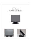
User Manual / Installation Guide 15" True Flat P-CAP Touch Monitor Warning! It will cause malfunction if the monitor is operating with unspecified power supply unit or incorrect power voltage. Do not exposure this unit in the rain or moisture environment to reduce the risk of fire or electric shock. Content: I. FCC Warning Statement................................................................................. 1 II. Introduction..................................................................................................... 2 Features......................................................................................................................................2 Unpacking the monitor ..............................................................................................................3 III. Installation....................................................................................................... 4 I/O placement.............................................................................................................................4 To PC .........................................................................................................................................4 Touch Driver installation ...........................................................................................................5 MSR installation (optional) .......................................................................................................7 Second Display (optional) .........................................................................................................8 Control Buttons........................................................................................................................10 Structure of OSD settings ........................................................................................................11 IV. For your safety.............................................................................................. 12 V. Support timing chart: ................................................................................... 12 VI. Mechanical Dimension................................................................................. 12 VII. Product General Specification .................................................................... 13 I. FCC Warning Statement WARNING Note: This equipment has been tested and found to comply with the limits for a Class B digital device, pursuant to Part 15 of FCC Rules. These limits are designed to provide reasonable protection against harmful interference in a residential installation. This equipment generates, uses and can radiate radio frequency energy and, if not installed and used in accordance with the instruction, may cause harmful interference to radio communications. However, there is no guarantee that interference will not occur in a particular installation. If this equipment does cause harmful interference to radio or television reception, which can be determined by turning the equipment off and on, the user is encouraged to try to correct the interference by one or more of the following measures: -Reorient or relocate the receiving antenna. -Increase the separation between the equipment and receiver. -Connect the equipment into an outlet on a circuit different from that to which the receiver is connected. -Consult the dealer or an experienced radio/TV technician for help. Notice: (1) A Unshielded-type power cord is required in order to meet FCC emission limits and also to prevent interference to the nearby radio and television reception. It is essential that only the supplied power cord by used. (2) Use only shielded cables to connect I/O devices to this equipment. (3) Changes or modifications not expressly approved by the party responsible for compliance could void the user’s authority to operate the equipment. Version. 1.0 1 II. Introduction 15" True Flat Touch Monitor is color TFT LCD monitor, integrate with projected capacitive touch, suitable for many types of application. Optional MSR and 2nd display, please contact our regional distributor for further information. Features - Optimal display resolution 1024 * 768 VESA 75 * 75 mm wall mount standard Durable and sturdy base design Optional 3 tracks Magnetic Strip Reader (MSR) Optional variety of 2nd display (8.4”) Adjustable viewing angel freely up to 90 degrees horizontally Low power consumption only 20W with CCFL backlight Version. 1.0 2 Unpacking the monitor - Put the monitor on a clean surface, make sure the box in upright position. Remove packing materials from inside of box. Check accessory Please make sure all the accessory are included: Standard Items a. b. d. c. e. f. a. LCD Monitor c. Touch driver / User Manual CD e. Power adaptor Optional Items a. b. b. 2nd display ( 8.4” ) a. MSR Version. 1.0 b. VGA cable d. USB Touch cable f. Power cable 3 III. Installation I/O placement 7 6 5 4 1 DC JACK 3 VGA 5 Dual USB A Type 7 RJ45(RS232) 3 2 1 2 DVI 4 USB B Type 6 RS232 To PC 1. Connect VGA cable from monitor to PC 2. Connect USB touch cable to PC 3. Connect DC plug to monitor and the other side to wall outlet Version. 1.0 4 Touch Driver installation P_CAP_Touch: 1. Double click “setup.exe” from driver menu 2. Click “Next” to start the setup program of eGalax Touch 3. Select “I accept the terms of the license agreement” 4. Click “Next” from Setup Type and click “Next” from License Agreement 5. Click “Next” from Setup Type Version. 1.0 6. Click “Next” from Setup Type 5 7. Select “Support Multi-Monitor System” and Click 8. “Choose Destination Location” and click “Next” “Next” 9. “Select Program Folder” and click “Next” 10.Click “Next” to start the eGalax Touch Setup 11. eGalax Touch Setup is running 12.Finish and create a eGalax Touch Utility shortcut on desktop Version. 1.0 6 MSR installation (optional) Components of MSR Kit: MSR Screws USB 1. 2. Version. 1.0 Slide the MSR into the right position of the System. Fasten the screws (x2). 7 Second Display (optional) Components of Second Display Kit: Metal Bracket Second Display Screws Screws USB Cable ❷ ❸ ❶ Fix the parts of Second Display modules as steps ❶ ❷ ❸ 1. as above picture shows. (detail steps as below) ❶ Put the second display upside down. ❷ Connect the USB cable to the Second Display Module ❸ Fasten the screws (x4) to fix metal bracket with the system. Version. 1.0 8 2. 3. 4. Version. 1.0 Fasten the scrws (x3) to fix the Second Display moudle with the System. Connect the USB cable to the System. Finish. 9 Control Buttons Auto Adjusting a.) Pressing to execute AUTO-Adjusting function. This function will set the monitor display area to the optimal position. b.) Sometimes this function can't achieve the optimal effects. Please follow the manual adjusting procedure. Menu When the light bar move other item, the key are used to select it, and read to adjust. Press the MENU key to activate the On Screen Display (OSD). Press twice to turn off the OSD. After 30 sec idle times, the OSD screen will automatically turn off. Power Use the power switch to turn the power ON or OFF. We recommend to turn your system power on first, then the LCD monitor. Up Down Version. 1.0 a.) When OSD mode is activated (When “MENU” key is pressed). The two keys are used to select the adjustment items. b.) When adjustment item is selected, the two keys are defined to decrease or increase the value of each selected item. 10 Structure of OSD settings First Level Second Level Auto Adjust Luminance Brightness Contrast Exit Geometry H. Position V. Position Clock Phase Exit Third Level Operating Procedure Press “UP” or “DOWN” to adjust H-phase & H-position & V-position clock automatically. Press “UP” key to increase brightness, “DOWN” key to decrease brightness. Press “UP” key to increase contrast, “DOWN” key to decrease contrast. Press “UP” key to shift screen right, “DOWN” key to shift screen left. Press “UP” key to shift picture upward, “DOWN” key to shift picture downward. Adjust sampling clock of analog to digital converter until clock is equal to pixel frequency of video input. By varying this “UP” “DOWN” control the exact sampling time within the pixel can be adjusted. 9300K 6500K 5800K Color Main Menu User Preset Red Press “UP” or “DOWN” to choose three types of color Green temperature 9300°k, 6500°k and user define. Blue Exit Exit OSD H. Position V. Position OSD Timeout Exit English French German Italian Language Spanish Japanese T. Chinese S. Chinese Color Recall Recall Recall All Exit Sharpness Display Miscellaneous Information Exit Adjust OSD frame horizontal location, press “UP” key to shift frame right, “DOWN” key to shift frame left , timeout and preset OSD. Adjust OSD frame vertical location, press “UP” key to shift frame upward, “UP” key to shift frame downward , timeout and preset OSD. Press “UP” or “DOWN” to choose any one of the following language, English, French, Germany, Italy, Spain , Japanese, Traditional Chinese and Simplified Chinese. Recall the default value. Press “UP” key to increase sharpness, “DOWN” key to decrease sharpness. Exit Version. 1.0 11 IV. For your safety 1. 2. 3. When move the monitor, always switch off power and disconnect all cables to avoid any danger. Please use the power and signal cables correctly when install or bend it. In case of notice any abnormal smell or noise, please stop operation and call the nearest dealer or service center. V. Support timing chart: Timing Mode Mode 1 Reference Resolution Standard 1024×768 VESA Pixel MHz 65.000 48.363 60.004 NO - - - - FH KHz FV Hz Interlace Mode 2 VESA 1024×768 75.000 56.476 70.069 NO Mode 3 VESA 1024×768 75.011 57.524 72.000 NO Mode 4 VESA 1024×768 78.750 60.023 75.029 NO H V Polarity Polarity 40 47,1 220 VI. Mechanical Dimension 70,8 220 175,48 35 60,7 339,3 278,6 ? 58 139,3 47,1 361,6 Version. 1.0 12 118,57 67,55 VII. Product General Specification Model Monitor Cabinet color Black Display size 15.0" Active Area 304 * 228 mm Optimal Resolution 1024 * 768 Color Arrangement RGB-stripe Brightness 250 cd/m² (typ) Contrast Ratio 600:1 Response Time 8 ms (typ) 160 degrees (H) Viewing Angle 160 degrees (V) Input Video Format VGA/DVI Input Video signal connector D-Sub 15 pins+DVI-D Touch Panel Projected capacitive Touch Interface USB Power consumption 20W Horizontal : 31.5 kHz~60.2 kHz Input Frequency Vertical : 56.3Hz~75Hz Power supply DC 12V +/- 10% Operating : 0℃~40℃ Temperature Storage : -10℃~50℃ Operating : 20%~80% Humidity Storage : 10%~90% Weight Version. 1.0 Monitor with stand 3.3kg(net) 4.7kg(net) Approvals CE, FCC Wall Mount VESA 75 * 75 mm 13