1
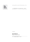
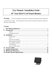
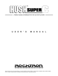
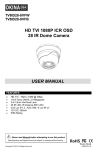
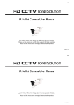
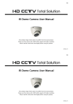
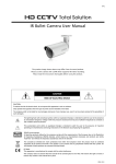
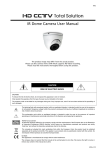
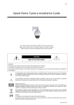
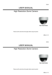
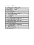
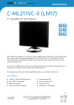
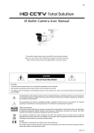
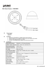
678Z IR Dome Camera User Manual The product image shown above may differ from the actual product. Please use this camera with a DVR which supports HD video recording. Please read the instructions thoroughly before using the product. t420a_V1.1 678Z IR Dome Camera User Manual The product image shown above may differ from the actual product. Please use this camera with a DVR which supports HD video recording. Please read the instructions thoroughly before using the product. t420a_V1.1 IMPORTANT SAFEGUARD CAUTION RISK OF ELECTRIC SHOCK CAUTION: To reduce the risk of electric shock, do not expose this apparatus to rain or moisture. Only operate this apparatus from the type of power source indicated on the label. The company shall not be liable for any damages arising out of any improper use, even if we have been advised of the possibility of such damages. The lightning flash with arrowhead symbol, within an equilateral triangle, is intended to alert the user to the presence of uninsulated “dangerous voltage” within the product’s enclosure that may be of sufficient magnitude to constitute a risk of electric shock to persons. This exclamation point within an equilateral triangle is intended to alert the user to the presence of important operating and maintenance (servicing) instructions in the literature accompanying the appliance. All lead-free products offered by the company comply with the requirements of the European law on the Restriction of Hazardous Substances (RoHS) directive, which means our manufacture processes and products are strictly “lead-free” and without the hazardous substances cited in the directive. The crossed-out wheeled bin mark symbolizes that within the European Union the product must be collected separately at the product end-of-life. This applies to your product and any peripherals marked with this symbol. Do not dispose of these products as unsorted municipal waste. Contact your local dealer for procedures for recycling this equipment. CE Mark This apparatus is manufactured to comply with the radio interference. The company does not warrant that this manual will be uninterrupted or error-free. We reserve the right to revise or remove any content in this manual at any time. IMPORTANT SAFEGUARD CAUTION RISK OF ELECTRIC SHOCK CAUTION: To reduce the risk of electric shock, do not expose this apparatus to rain or moisture. Only operate this apparatus from the type of power source indicated on the label. The company shall not be liable for any damages arising out of any improper use, even if we have been advised of the possibility of such damages. The lightning flash with arrowhead symbol, within an equilateral triangle, is intended to alert the user to the presence of uninsulated “dangerous voltage” within the product’s enclosure that may be of sufficient magnitude to constitute a risk of electric shock to persons. This exclamation point within an equilateral triangle is intended to alert the user to the presence of important operating and maintenance (servicing) instructions in the literature accompanying the appliance. All lead-free products offered by the company comply with the requirements of the European law on the Restriction of Hazardous Substances (RoHS) directive, which means our manufacture processes and products are strictly “lead-free” and without the hazardous substances cited in the directive. The crossed-out wheeled bin mark symbolizes that within the European Union the product must be collected separately at the product end-of-life. This applies to your product and any peripherals marked with this symbol. Do not dispose of these products as unsorted municipal waste. Contact your local dealer for procedures for recycling this equipment. CE Mark This apparatus is manufactured to comply with the radio interference. The company does not warrant that this manual will be uninterrupted or error-free. We reserve the right to revise or remove any content in this manual at any time. TABLE OF CONTENTS FEATURES PACKAGE CONTENT DIMENSIONS* SPECIFICATIONS* INSTALLATION WIRE INDICATION FOR ALARM CONNECTION CONNECTION CAMERA PARAMETERS 1 1 2 3 4 7 8 9 TABLE OF CONTENTS FEATURES PACKAGE CONTENT DIMENSIONS* SPECIFICATIONS* INSTALLATION WIRE INDICATION FOR ALARM CONNECTION CONNECTION CAMERA PARAMETERS 1 1 2 3 4 7 8 9 FEATURES 1. 1/2.8” CMOS Sensor with 1080P video output 2. External alarm I/O device connection 3. WDR to increase image recognizability in overexposure and dark areas 4. 3-axis mechanism for flexible ceiling and wall-mount installation 5. IR effective distance up to 15 meters for 24-hour surveillance 6. Camera parameters adjustable when used with HD CCTV DVR PACKAGE CONTENT IR dome camera User manual Accessories 1 FEATURES 1. 1/2.8” CMOS Sensor with 1080P video output 2. External alarm I/O device connection 3. WDR to increase image recognizability in overexposure and dark areas 4. 3-axis mechanism for flexible ceiling and wall-mount installation 5. IR effective distance up to 15 meters for 24-hour surveillance 6. Camera parameters adjustable when used with HD CCTV DVR PACKAGE CONTENT IR dome camera User manual 1 Accessories DIMENSIONS* *Dimensional Tolerance: ± 5mm 2 DIMENSIONS* *Dimensional Tolerance: ± 5mm 2 SPECIFICATIONS* Pick-up Element Number of Pixels Video Frame Rate Min. Illumination S/N Ratio Shutter Speed Lens Lens Angle IR LED IR Effective Distance IR Shift IRIS Mode White Balance AGC WDR External alarm I/O Operating Temperature Power Source (±10%) Current Consumption (±10%) Optional Peripherals 1/2.8" SONY CMOS image sensor 1936(H) × 1096(V) 1080P@30fps / 1080P@25fps 0.1 Lux / F1.8, 0 Lux (IR LED ON) More than 48dB (AGC OFF) 1/10,000 ~ 1/7.5 (Slow shutter) f3.6mm / F1.8 87° (Horizontal) / 46° (Vertical) / 104° (Diagonal) 12 units Up to 15 meters YES AES ATW Auto YES (120dB) YES (1 input / 1 output) 0℃ ~ 40℃ DC12V / 1A 385mA (IR ON); 280mA (IR OFF) Wall-mount bracket (PAVM542-BKT(B)) * The specifications are subject to change without notice. 3 SPECIFICATIONS* Pick-up Element Number of Pixels Video Frame Rate Min. Illumination S/N Ratio Shutter Speed Lens Lens Angle IR LED IR Effective Distance IR Shift IRIS Mode White Balance AGC WDR External alarm I/O Operating Temperature Power Source (±10%) Current Consumption (±10%) Optional Peripherals 1/2.8" SONY CMOS image sensor 1936(H) × 1096(V) 1080P@30fps / 1080P@25fps 0.1 Lux / F1.8, 0 Lux (IR LED ON) More than 48dB (AGC OFF) 1/10,000 ~ 1/7.5 (Slow shutter) f3.6mm / F1.8 87° (Horizontal) / 46° (Vertical) / 104° (Diagonal) 12 units Up to 15 meters YES AES ATW Auto YES (120dB) YES (1 input / 1 output) 0℃ ~ 40℃ DC12V / 1A 385mA (IR ON); 280mA (IR OFF) Wall-mount bracket (PAVM542-BKT(B)) * The specifications are subject to change without notice. 3 INSTALLATION Step1: Separate the dome cover from the camera. Step2: Make sure the screw holes on the plate are aligned with the holes on the camera base. If not, slightly loosen the two screws on the plate and rotate it. Step3: Mark the locations of two screw holes on the ceiling or wall for installing the camera later. NOTE: An installation sticker could be downloaded from www.surveillance-download.com/user/503_installation_sticker.pdf. 4 INSTALLATION Step1: Separate the dome cover from the camera. Step2: Make sure the screw holes on the plate are aligned with the holes on the camera base. If not, slightly loosen the two screws on the plate and rotate it. Step3: Mark the locations of two screw holes on the ceiling or wall for installing the camera later. NOTE: An installation sticker could be downloaded from www.surveillance-download.com/user/503_installation_sticker.pdf. 4 -- For cabling behind the ceiling or wall, mark the location for one more hole for the camera cable to go through; -- For cabling along the ceiling or wall, do as indicated below for the cable to go through. Step4: Fix the camera to the ceiling or wall with the supplied screws. Step5: Connect your camera to power. 5 -- For cabling behind the ceiling or wall, mark the location for one more hole for the camera cable to go through; -- For cabling along the ceiling or wall, do as indicated below for the cable to go through. Step4: Fix the camera to the ceiling or wall with the supplied screws. Step5: Connect your camera to power. 5 Step6: Pan, tilt and rotate the lens itself to adjust the position and viewing angle of the camera, and fasten the two screws on the plate to fix. Step7: Replace the dome cover back to the camera. NOTE: Please wipe the inner part of the dome cover against the lens for clear images. 6 Step6: Pan, tilt and rotate the lens itself to adjust the position and viewing angle of the camera, and fasten the two screws on the plate to fix. Step7: Replace the dome cover back to the camera. NOTE: Please wipe the inner part of the dome cover against the lens for clear images. 6 WIRE INDICATION FOR ALARM CONNECTION COLOR FUNCTION Yellow ALARM IN Blue ALARM OUT Black GND 7 WIRE INDICATION FOR ALARM CONNECTION COLOR FUNCTION Yellow ALARM IN Blue ALARM OUT Black GND 7 CONNECTION 1. DC12V Input Terminal Connect the power terminal of the camera to a DC 12V regulated power supply. Note: Please use the correct power adaptor, DC12V (regulated), to operate this unit. The power tolerance of this unit is DC12V ± 10%. Over maximum DC 12V power input will damage this unit. 1. Video Output Connector (VIDEO OUT) Connect the camera video output to the video input of a DVR with 75Ω coaxial cable. Note: To ensure the camera has sufficient protection against moisture, an extra waterproof measure, such as by using an insulating tape, must be used to cover the power and video connectors after connection. 8 CONNECTION 1. DC12V Input Terminal Connect the power terminal of the camera to a DC 12V regulated power supply. Note: Please use the correct power adaptor, DC12V (regulated), to operate this unit. The power tolerance of this unit is DC12V ± 10%. Over maximum DC 12V power input will damage this unit. 1. Video Output Connector (VIDEO OUT) Connect the camera video output to the video input of a DVR with 75Ω coaxial cable. Note: To ensure the camera has sufficient protection against moisture, an extra waterproof measure, such as by using an insulating tape, must be used to cover the power and video connectors after connection. 8 CAMERA PARAMETERS On the DVR live view, right click to show the DVR main menu, and select ADVANCED CONFIG DCCS. Then, select the channel which connects this camera, and click SETUP to enter the menu of camera parameters. ADVANCED CONFIG CAMERA DETECTION ALERT NETWORK DISPLAY RECORD DEVICES DCCS NOTIFY CH1 CH2 MENU CH3 CH4 SETUP DEVICE XXXXX CONNECTION OK 9 CAMERA PARAMETERS On the DVR live view, right click to show the DVR main menu, and select ADVANCED CONFIG DCCS. Then, select the channel which connects this camera, and click SETUP to enter the menu of camera parameters. ADVANCED CONFIG CAMERA DETECTION ALERT NETWORK DISPLAY RECORD DEVICES DCCS NOTIFY CH1 CH2 MENU CH3 CH4 SETUP DEVICE XXXXX CONNECTION OK 9 MENU DESCRIPTION BRIGHTNESS Click the current value to manually adjust the brightness of the image. The higher the value, the brighter the image. CONTRAST Click the current value to manually adjust the contrast of the image. The higher the value, the higher the contrast ratio. HUE Click the current value to manually adjust the hue of the image. SATURATION Click the current value to manually adjust the saturation of the image. The higher the value, the more saturated the image. VIDEO FORMAT Select the video format: NTSC / PAL. WHITE BALANCE Process the current image to retain color balance over a color temperature range. The options are: Auto, 2500K, 3200K, 4200K, 5800K & 9500K. 9500K = Partially cloudy; 5800K = Mid summer; 4200K = White fluorescent; 3200K = Halogen light bulb; 2500K = Halogen light bulb. 10 MENU DESCRIPTION BRIGHTNESS Click the current value to manually adjust the brightness of the image. The higher the value, the brighter the image. CONTRAST Click the current value to manually adjust the contrast of the image. The higher the value, the higher the contrast ratio. HUE Click the current value to manually adjust the hue of the image. SATURATION Click the current value to manually adjust the saturation of the image. The higher the value, the more saturated the image. VIDEO FORMAT Select the video format: NTSC / PAL. WHITE BALANCE Process the current image to retain color balance over a color temperature range. The options are: Auto, 2500K, 3200K, 4200K, 5800K & 9500K. 9500K = Partially cloudy; 5800K = Mid summer; 4200K = White fluorescent; 3200K = Halogen light bulb; 2500K = Halogen light bulb. 10 MENU DESCRIPTION SHARPNESS Sharpness enhances the clarity of image detail by adjusting the aperture and sharpening the edges in the pictures. Click the current value to manually adjust the sharpness of the image. The higher the value, the sharper the image. SLOW SHUTTER Slow shutter is used to increase the exposure time to get clearer image, for example, at night. It’s enabled only in the dark environment. The options are: AUTO, 1/15 and 1/6. MIRROR Select ON to turn the images horizontally based on your installation situation when necessary. FLIP Select ON to flip the image 180° when necessary. 3D DENOISE Click and drag the slider to adjust the level from 0 ~ 5 to decrease the noise shown in the dark environment. 3D denoise analyzes successive pictures to decrease the noise dramatically, but the moving objects might be shown as blurred. 11 MENU DESCRIPTION SHARPNESS Sharpness enhances the clarity of image detail by adjusting the aperture and sharpening the edges in the pictures. Click the current value to manually adjust the sharpness of the image. The higher the value, the sharper the image. SLOW SHUTTER Slow shutter is used to increase the exposure time to get clearer image, for example, at night. It’s enabled only in the dark environment. The options are: AUTO, 1/15 and 1/6. MIRROR Select ON to turn the images horizontally based on your installation situation when necessary. FLIP Select ON to flip the image 180° when necessary. 3D DENOISE Click and drag the slider to adjust the level from 0 ~ 5 to decrease the noise shown in the dark environment. 3D denoise analyzes successive pictures to decrease the noise dramatically, but the moving objects might be shown as blurred. 11 MENU DESCRIPTION 2D DENOISE Click and drag the slider to adjust the level from 0 ~ 5 to decrease the noise shown in the dark environment. 2D denoise analyzes only a single picture to decrease the noise. The moving objects can remain smooth edges, but the effect might be limited. EXPOSURE VALUE Drag the slider to adjust the exposure level from 0 ~ 4. The higher the value, the brighter the image. WIDE DYNAMIC RANGE Wide Dynamic Range (WDR) is used when users need to increase image recognizability in an environment where very bright and dark areas exist simultaneously. The options are: LOW / MIDDLE / HIGH / OFF. The more extreme the bright and dark areas exist simultaneously in an environment, the higher the value should choose to get clear images. 12 MENU DESCRIPTION 2D DENOISE Click and drag the slider to adjust the level from 0 ~ 5 to decrease the noise shown in the dark environment. 2D denoise analyzes only a single picture to decrease the noise. The moving objects can remain smooth edges, but the effect might be limited. EXPOSURE VALUE Drag the slider to adjust the exposure level from 0 ~ 4. The higher the value, the brighter the image. WIDE DYNAMIC RANGE Wide Dynamic Range (WDR) is used when users need to increase image recognizability in an environment where very bright and dark areas exist simultaneously. The options are: LOW / MIDDLE / HIGH / OFF. The more extreme the bright and dark areas exist simultaneously in an environment, the higher the value should choose to get clear images. 12 MENU DESCRIPTION FIXED SHUTTER Shutter Speed is a function that can adjust the duration of the electronic shutter to produce optimum image quality. Select the shutter speed suitable for your environment. The options are: OFF, FIX 1/15, FIX 1/25, FIX 1/30, FIX 1/50, FIX 1/60, FIX 1/100, FIX 1/120, FIX 1/250, FIX 1/500, FIX 1/1000, FIX 1/2000, FIX 1/5000, FIX 1/10000. DEFOG Select ON to enable the defog function in poor weather conditions such as fog, smog or smoke. The captured image can be improved. IR CONTROL Select AUTO to automatically enable IR LEDs at night or in the dark environment, or OFF to disable this function. IR TURN ON LEVEL Select the level for IR light to activate. 0 ~ 20. The higher the value, the more sensitive the IR light to activate. 13 MENU DESCRIPTION FIXED SHUTTER Shutter Speed is a function that can adjust the duration of the electronic shutter to produce optimum image quality. Select the shutter speed suitable for your environment. The options are: OFF, FIX 1/15, FIX 1/25, FIX 1/30, FIX 1/50, FIX 1/60, FIX 1/100, FIX 1/120, FIX 1/250, FIX 1/500, FIX 1/1000, FIX 1/2000, FIX 1/5000, FIX 1/10000. DEFOG Select ON to enable the defog function in poor weather conditions such as fog, smog or smoke. The captured image can be improved. IR CONTROL Select AUTO to automatically enable IR LEDs at night or in the dark environment, or OFF to disable this function. IR TURN ON LEVEL Select the level for IR light to activate. 0 ~ 20. The higher the value, the more sensitive the IR light to activate. 13 MENU DESCRIPTION IR DELAY TIME Set the delay time from 1 ~ 60 in second after which the day and night switch is made, or select 0 to disable this function. This is used for the environment where the light condition may change suddenly and usually last for a short time, for example, the entrance of a parking lot. It may cause the day & night mode switching constantly and damage the camera. With this function, the camera will delay the mode switch at night since the light change is temporary and unnecessary to pay attention. RESET DEFAULT Click to reset all camera settings to their default values. The camera will reboot to complete the reset process. REBOOT THE SYSTEM Click to reboot the camera if necessary. 14 MENU DESCRIPTION IR DELAY TIME Set the delay time from 1 ~ 60 in second after which the day and night switch is made, or select 0 to disable this function. This is used for the environment where the light condition may change suddenly and usually last for a short time, for example, the entrance of a parking lot. It may cause the day & night mode switching constantly and damage the camera. With this function, the camera will delay the mode switch at night since the light change is temporary and unnecessary to pay attention. RESET DEFAULT Click to reset all camera settings to their default values. The camera will reboot to complete the reset process. REBOOT THE SYSTEM Click to reboot the camera if necessary. 14