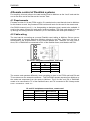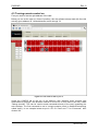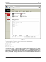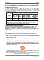
1
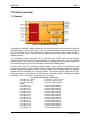
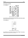
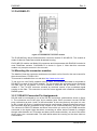
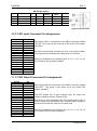
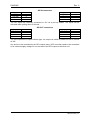
D422-MG RS-422 Multiplexer with GPI I/O User manual Rev. 6 Nevion HQ: Nevion Europe, P.O. Box 1020, 3204 Sandefjord, Norway Tel: +47 33 48 99 99 – Fax: +47 33 48 99 98 – www.nevion.com D422-MG Rev. 6 Nevion Support Nevion Europe Nevion USA P.O. Box 1020 3204 Sandefjord, Norway Support phone 1: +47 33 48 99 97 Support phone 2: +47 90 60 99 99 1600 Emerson Avenue Oxnard, CA 93033, USA Toll free North America: (866) 515-0811 Outside North America: +1 (805) 247-8560 E-mail: [email protected] See http://www.nevion.com/support/ for service hours for customer support globally. Revision history Current revision of this document is the uppermost in the table below. Rev. Repl. Date Sign 6 5 2011-09-28 JD 5 4 3 2 1 4 3 2 1 0 2011-08-15 2009-07-30 2008-07-24 2007-10-25 2007-10-05 MS OEH AS AS AS 0 C 2006-05-11 OEH C B B A 2004.06.08 2004.05.28 OEH OEH A Change description Added information on remote control of Flashlink / FlashCase Added single slot backplane for FlashCase Added single slot backplane pinning Added Declaration of Conformity. New front page. Added Materials Declaration and EFUP GPI monitoring and control via GYDA Added RS422 VTR master and slave pinouts Added CWDM channels 9-16. Added power/latency specification. Preliminary version. Pre production run. nevion.com | 2 D422-MG Rev. 6 Contents Revision history .......................................................................................................... 2 1 Product overview ..................................................................................................... 4 1.1 General ........................................................................................................................... 4 2 Specifications .......................................................................................................... 5 2.1 Electrical.......................................................................................................................... 5 2.2 Inputs .............................................................................................................................. 5 2.2.1 RS-422 ......................................................................................................................... 5 2.2.2 GPI ............................................................................................................................... 5 2.2.3 Optical input ................................................................................................................. 5 2.3 Outputs............................................................................................................................ 5 2.3.1 RS-422 ......................................................................................................................... 5 2.3.2 GPI ............................................................................................................................... 5 2.3.3 Optical output ............................................................................................................... 6 3 Connector modules ................................................................................................. 7 3.1 D-422-MG-C1 .................................................................................................................. 7 3.2 D-422-MG-C2 .................................................................................................................. 7 3.3 D-422-MG-C3 .................................................................................................................. 8 3.4 Mounting the connector modules ..................................................................................... 8 3.5 C1 RS-422 Connector Pin Assignments .......................................................................... 8 3.6 C1 GPI Input Connector Pin Assignments ....................................................................... 9 3.7 C1 GPI Output Connector Pin Assignments .................................................................... 9 3.8 C2 DB25 Connector Pin Assignments ............................................................................10 3.9 C3 Molex KK Connector Pin Assignments ......................................................................10 4 Remote control of Flashlink systems ..................................................................... 12 4.1 Requirements .................................................................................................................12 4.2 Cable wiring....................................................................................................................12 4.3 Turning remote control on...............................................................................................13 5 Operational status monitoring ................................................................................ 16 5.1 GYDA – Monitoring and control ......................................................................................16 5.2 Front Panel - Status Monitoring ......................................................................................16 6 Operation ............................................................................................................... 17 General environmental requirements for Nevion equipment..................................... 18 Product Warranty ...................................................................................................... 19 Appendix A Materials declaration and recycling information..................................... 20 A.1 Materials declaration ......................................................................................................20 Environmentally-friendly use period ......................................................................................20 A.2 Recycling information .....................................................................................................21 EC Declaration of Conformity ................................................................................... 22 nevion.com | 3 D422-MG Rev. 6 1 Product overview 1.1 General Figure 1: D-422-MG Block diagram The flashlink D-422-MG module provides an economical solution for transmitting RS-422 and GPI data signals via fiber optic cable. A pair of D-422-MG allows bi-directional transmission of up to 8 RS-422 and 16 GPI data lines for distances over 60km. When access to fiber is limited, D-422-MG can be combined with the flashlink optical multiplexing WDM, CWDM or DWDM products. The D-422-MG module multiplexes up to 8 RS-422 and 16 GPI inputs into an outgoing datastream while at the same time demultiplexing an incoming datastream into 8 RS-422 and 16 GPI outputs. The outgoing multiplexed stream is available both as an optical signal and as an electrical signal for use with a flashlink multichannel DWDM system. As stand alone unit, the D-422-MG module utilises 2 fiber strands for bi-directional data transport. Using either 2 fiber strands or optical multiplexing technology guarantees minimum possible latency for applications where timing is crucial. The D-422-MG module is supplied together with the D-422-MG-C1 connector module. The optical output is made with a FabryPerot laser diode for 1310±40nm or a DFB laser for 1550±40nm and the CWDM wavelengths according to ITU-T G.694 from 1470±6nm up to 1610±6nm. The product is available in 19 versions: D-422-MG-13T -7.5dBm D-422-MG-13T 0 dBm D-422-MG-15T 0 dBm CWDM D-422-MG-C1470 D-422-MG-C1490 D-422-MG-C1510 D-422-MG-C1530 D-422-MG-C1550 D-422-MG-C1570 D-422-MG-C1590 D-422-MG-C1610 D-422-MG-C1270 D-422-MG-C1290 D-422-MG-C1310 D-422-MG-C1330 D-422-MG-C1350 D-422-MG-C1370 D-422-MG-C1390 D-422-MG-C1410 1310±40nm -7.5 dBm F-P laser 1310±40nm 0 dBm F-P laser 1550±40nm 0 dBm DFB laser 1470±6nm 0dBm DFB laser 1490±6nm 0dBm DFB laser 1510±6nm 0dBm DFB laser 1530±6nm 0dBm DFB laser 1550±6nm 0dBm DFB laser 1570±6nm 0dBm DFB laser 1590±6nm 0dBm DFB laser 1610±6nm 0dBm DFB laser 1270±6nm 0dBm DFB laser 1290±6nm 0dBm DFB laser 1310±6nm 0dBm DFB laser 1330±6nm 0dBm DFB laser 1350±6nm 0dBm DFB laser 1370±6nm 0dBm DFB laser 1390±6nm 0dBm DFB laser 1410±6nm 0dBm DFB laser nevion.com | 4 D422-MG Rev. 6 2 Specifications 2.1 Electrical Power: Control: Monitoring: RS-422 Latency: GPI Latency: +5V DC 0.8A 4W, Gyda system controller. Front panel LEDs and Gyda system controller 500ns maximum single direction latency including 1m of fiber. Additional latency 5µs/km of fiber. 5µs maximum single direction latency including 1m of fiber. Additional latency 5µs/km of fiber. 2.2 Inputs 2.2.1 RS-422 Signal format: Connector: Bit Rate: RS-422 RJ-45 DC up to 115.2 kbps 2.2.2 GPI Connector: Signal type: DSUB Internal pull 25 up to 5V 2.2.3 Optical input Sensitivity: Max. input power: Optical wavelengths: Transmission circuit fiber: Return loss: Connector: better than –30dBm -3dBm 1310nm, 1550nm Multi Mode 50/125um, Single Mode 9/125um compatible > 26dB SC/UPC, Return Loss better than 40dB 2.3 Outputs 2.3.1 RS-422 Signal format: Connector: Bit Rate: RS-422 RJ-45 DC up to 115.2 kbps 2.3.2 GPI Connector: Signal type: Maximum voltage: Maximum current: DSUB-25 Open collector transistor. 30 V 100 mA nevion.com | 5 D422-MG Rev. 6 2.3.3 Optical output Transmission circuit fibre: Light source: Optical wavelength (ver. 13T): Optical power: Optical power (option): Optical wavelength (ver. 15T): Optical power: Optical wavelength (ver. C1nn0): Optical power: Jitter (UI=unit interval): Return loss: Maximum reflected power: Connector: Single Mode F-P/DFB Laser 1310nm ±40nm -7.5 dBm 0 dBm 1550nm ±40nm 0 dBm 1270, 1290, 1310, 1330, 1350, 1370, 1390, 1410, 1470, 1490, 1510, 1530, 1550, 1570, 1590, 1610nm ±6nm as per ITU-T G.694.2 0 dBm Max. 0.135 UI Typ. > 40 dB 4% SC/UPC nevion.com | 6 D422-MG Rev. 6 3 Connector modules 3.1 D-422-MG-C1 Figure 2: D-422-MG-C1 Connector module The D-422-MG has a dedicated connector module: D-422-MG-C1. This module is mounted at the rear of the sub-rack. The module is shown in figure 2. Note that this connector module always occupies two (2) slots in the sub-rack. 3.2 D-422-MG-C2 Figure 3: D-422-MG-C2 Connector module The D-422-MG also has an alternative connector module: D-422-MG-C2. This module is mounted at the rear of the sub-rack. The module is shown in figure 3. Note that this connector module only occupies one slot in the sub-rack. nevion.com | 7 D422-MG Rev. 6 3.3 D-422-MG-C3 Figure 4: D-422-MG-C3 Connector module The D-422-MG also has a third alternative connector module: D-422-MG-C3. This module is meant for Nevion FlashCase outside broadcast housing. D-422-MG-C3 module use Molex KK connectors and interconnects with RJ45-KK included in most FlashCase variants. D-422-MG-C3 is shown in figure 4. Note that this connector module only occupies one slot in the sub-rack. 3.4 Mounting the connector modules The details of how the connector modules are mounted, can be found in the user manual for the sub-rack frame: FR-2RU-10-2. This manual is available from our web site: http://www.nevion.com/ To set up a link, two D-422 modules must be used. The RS-422 data cable is connected to RS-422/E1 on each of the D-422 modules. The two modules are connected to the fibres with one fiber from TX on module 1 to RX on module 2, and from RX on module 1 to TX on module 2. The TX UPG connector contains an electrical version of the modulated signal running on the fiber. This connector is used for future upgrade with a flashlink multichannel DWDM system. 3.5 C1 RS-422 Connector Pin Assignments RS-422 shall be connected to one of the RS-422 connectors, positioned as shown in figure 2. The connectors are RJ-45 style, 8-pin modular jacks. Each connector has two RS-422 ports, referred to as ports 1 and 2 in the below table. In the event that only one port is in use, an RJ-11 style 4/6 (4-wire, 6-position) jack can be used instead. Signals marked as inputs on the D-422-MG shall be connected to the outputs of the connected devices, and vice versa. The columns for DB9 VTR Master and Slave show which pin on the 9 pin DSUB should be connected to the signal. Note that when connecting an active device instead of a straightthrough cable between a VTR master and slave (device and controller), one end of the active device must use a crossed cable. The table below takes the crossing on the slave side into consideration. nevion.com | 8 D422-MG Rev. 6 RS-422 pin layout: Signal Name Port1 Port2 DB9 VTR Master DB9 VTR Slave Mode RX + RX TX + TX - Receive Pos. Receive Neg. Transmit Pos. Transmit Neg. Pin 3 Pin 6 Pin 5 Pin 4 Pin 1 Pin 2 Pin 7 Pin 8 Pin 3 Pin 8 Pin 7 Pin 2 Pin 7 Pin 2 Pin 3 Pin 8 Input Input Output Output Figure 5: RS-422 outlet 3.6 C1 GPI Input Connector Pin Assignments Input 1 2 3 4 5 6 7 8 9 10 11 12 13 14 15 16 Pin 12 24 23 10 9 21 20 7 6 18 17 4 3 15 14 1 GPI inputs shall be connected to the DB25 connector marked “GPI IN”. The pinout is the same as for the VikinX GPI panels, see table. All inputs are internally connected to +5V via a pull-up resistor. The inputs will be activated when pulling them to Ground. Ground is available on the following pins: 2, 5, 8, 11, 13, 16, 19, 22, 25 and on the connector chassis. 3.7 C1 GPI Output Connector Pin Assignments Output Pin 1 2 3 4 5 6 7 8 9 10 11 12 13 14 15 16 12 24 23 10 9 21 20 7 6 18 17 4 3 15 14 1 GPI outputs shall be connected to the DB25 connector marked “GPI OUT”. The pinout is the same as for the VikinX GPI panels, see table. The GPI outputs are of open collector type. An output can switch a maximum load of 100mA at 30V. Any device to be controlled by the GPI outputs (lamp, LED or similar) needs to be connected to an external supply voltage on one end and to the GPI output on the other end. Ground is available on the following pins: 2, 5, 8, 11, 13, 16, 19, 22, 25 and on the connector chassis. nevion.com | 9 D422-MG Rev. 6 3.8 C2 DB25 Connector Pin Assignments When sold with the C2 backplane, a subset of the inputs and outputs are available on a single DB25 connector with the following pinout: Output Pin TX1+ TX1RX1+ RX1TX2+ TX2RX2+ RX2GPI IN1 GPI IN2 GPI IN3 GPI IN4 GPI OUT1 GPI OUT2 GPI OUT3 GPI OUT4 1 14 15 3 4 17 18 6 7 9 10 12 20 21 23 24 Signals marked as inputs on the D-422-MG shall be connected to the outputs of the connected devices, and vice versa. Note that when connecting an active device instead of a straightthrough cable between a VTR master and slave (device and controller), one end of the active device must use a crossed cable (the VTR slave inputs are named TX and outputs are named RX). The GPI inputs are internally connected to +5V via a pull-up resistor. The inputs will be activated when pulling them to Ground. The GPI outputs are of open collector type. An output can switch a maximum load of 100mA at 30V. Any device to be controlled by the GPI outputs (lamp, LED or similar) needs to be connected to an external supply voltage on one end and to the GPI output on the other end. Ground is available on the following pins: 2, 5, 8, 11, 13, 16, 19, 22, 25 and on the connector chassis. 3.9 C3 Molex KK Connector Pin Assignments When sold with the C3 backplane, a subset of the inputs and outputs are available on a several Molex KK connectors with the following pinouts: RS422 connectors Output Pin RX+ RXTX+ TX- 1 2 3 4 Signals marked as inputs on the D-422-MG shall be connected to the outputs of the connected devices, and vice versa. Note that when connecting an active device instead of a straight-through cable between a VTR master and slave (device and controller), one end of the active device must use a crossed cable (the VTR slave inputs are named TX and outputs are named RX). Note that the RS232 ports 1 and 2 are unused when used with D-422-MG module nevion.com | 10 D422-MG Rev. 6 GPI IN connectors Output Pin Output Pin GPI IN1 GPI IN2 GPI IN3 Ground 1 2 3 4 GPI IN4 GPI IN5 GPI IN6 Ground 1 2 3 4 The GPI inputs are internally connected to +5V via a pull-up resistor. The inputs will be activated when pulling them to Ground. GPI OUT connectors Output Pin Output Pin GPI OUT 1 GPI OUT 2 GPI OUT 3 Ground 1 2 3 4 GPI OUT 4 GPI OUT 5 GPI OUT 6 Ground 1 2 3 4 The GPI outputs are of open collector type. An output can switch a maximum load of 100mA at 30V. Any device to be controlled by the GPI outputs (lamp, LED or similar) needs to be connected to an external supply voltage on one end and to the GPI output on the other end. nevion.com | 11 D422-MG Rev. 6 4 Remote control of Flashlink systems For simplicity, this text refers to the card residing local to Multicon as the “local” card and the one at the other end of the fiber as the “remote” card. 4.1 Requirements Firmware revision 2.2.0 and FPGA revision 5 is needed on the card that sits local to Multicon for this feature to work. Any firmware/FPGA revision will work for the card in the remote end. One RS422 channel (out of 2, 4 or 8 depending on backplane type) needs to be available. It must be the same channel for both cards, local and remote. The local card needs to be set up through the debug interface of Multicon (or PC with RS422 and serial port software). 4.2 Cable wiring The local card is connecting as a normal Flashlink card, talking to Multicon. But we use an external cable to transmit data from Multicon directly to the fiber. Data from the fiber is transmitted by the on-board MCU on the internal flashlink bus. Therefore, we only need 2 wires, RX+ of D422-MG is connected to RX+ of the flashlink frame, and likewise with RX-. C3 and C1 backplane connections, local card D422-MGC3 D422-MGC1 Flashlink subrack 1 2 - 3 6 - 1 2 - The remote card operates differently, here everything is done in the FPGA and both RX and TX are done over the external connectors . This D422-MG repeats requests from Multicon to the cards and responses from the cards to Multicon. Thus, for this end, RX of D422-MG needs to be connected to TX of the flashlink frame, and TX connected to RX. Always make sure + connects to + and - to -. C3 and C1 backplane connections, remote card D422-MG-C3 D422-MG-C1 (Port 1,3,5,7) D422-MG-C1 (Port 2,3,6,8) Flashlink 1 2 3 4 5 4 3 6 7 8 1 2 1 2 3 6 nevion.com | 12 D422-MG Rev. 6 4.3 Turning remote control on First you need to find the right address of the card. Below you can se the card is in frame 0 position 4 but the software always start with 0 so this actually gives address 03. Valid addresses are 00 through 79. Figure 6: Local card in rack 0, pos 4. Under the CONFIG tab at the top of the Multicon web interface (login required with administrative privileges, see Multicon manual for more info on this) there is an entry called “Debug terminal”. This can be used to send commands directly to the card, bypassing the web interface. The first command to use is a single question mark (in flashlink-terminology called “hello”). In our example below we put in “03” for “Card” and “?” for “Command”, then clicked “Ok”. nevion.com | 13 D422-MG Rev. 6 Figure 7: The command “0319?” was then sent to the card, which responded with 1903D422-MG/1310nm,-7.5dBm hw rev 1.0 sw rev 2.2.0 fpga rev 5 protocol ver 1.0 The command “remote” is used to enable or disable remote Flashlink control. To disable: “remote 0”. To enable on port 1 use the command “remote 1”, and so on up to port 8. The example above shows selecting port 1 for remote control. Below is shown the result, frame 5 was in our example sitting at the remote end of the D422-MG fiber link, and wired up according to the previous chapter. nevion.com | 14 D422-MG Rev. 6 Figure 8: Sending the command “remote conf” displays back which channel (if any) that is being used for remote Flashlink control. The readback uses same format as the “remote” command itself. nevion.com | 15 D422-MG Rev. 6 5 Operational status monitoring The status of the module can be monitored in two ways. GYDA system controller module. LED’s at the front of the sub-rack. The LED’s are mounted on the module itself, whereas the GYDA-SC controller is a separate flashlink module which presents the status of the flashlink modules in the frame(s) as a web site. The functions of the two monitoring systems are described below. 5.1 GYDA – Monitoring and control From within GYDA it is possible to have alarms on loss of signal, loss of reclocker lock, voltages, laser failure etc. As of firmware version 2.0.0 of D-422-MG it is also possible to have alarms on each of the 16 GPI inputs, as well as the 16 GPI outputs. Only the GPI inputs have alarms attached to them by default. Also, the same firmware version enables control of the GPI outputs, so each output can follow remote input, drive active low or set high impedance. All these functions are available from both web and SNMP. This means that spare GPI inputs and outputs on D-422-MG can be used to extend GYDA with more inputs and outputs. 5.2 Front Panel - Status Monitoring The status of the module can be easily monitored visually by the LED’s at the front of the module. The LED’s are visible through the front panel as shown in the figure below. Figure 9: LED overview of D-422-MG (Text not printed on the front panel).The D-422-MG has 3 LED’s. The colours of each of the LED’s have different meanings as shown in the table below. Diode \ state Status Loss of signal Laser fail Red LED Module initialising (takes app 1 sec). The laser is turned off. Module is faulty (fuse blown etc). No optical input signal, check fibre connection and card in opposite end. Laser is malfunctioning. Green LED Module self-test is OK and power is present. No light Module has no power. Optical input signal present. Laser is ok. nevion.com | 16 D422-MG Rev. 6 6 Operation Guidelines to limit hazards from laser exposure. All the available EO units in the flashlink range include a laser. Therefore this note on laser safety should be read thoroughly. The lasers emit light at wavelengths around 1310 nm or 1550 nm. This means that the human eye cannot see the beam, and the blink reflex cannot protect the eye. (The human eye can see light between 400 nm to 700 nm). A laser beam can be harmful to the human eye (depending on laser power and exposure time). Therefore: !! BE CAREFUL WHEN CONNECTING / DISCONNECTING FIBER PIGTAILS (ENDS). NEVER LOOK DIRECTLY INTO THE PIGTAIL OF THE LASER/FIBER. NEVER USE MICROSCOPES, MAGNIFYING GLASSES OR EYE LOUPES TO LOOK INTO A FIBER END. USE LASER SAFETY GOGGLES BLOCKING LIGHT AT 1310 nm AND AT 1550 nm Instruments exist to verify light output power: Power meters, IR-cards etc. flashlink features: All the laser module cards in the flashlink product range, are Class 1 laser products according to IEC 825-1 1993, and class I according to 21 CFR 1040.10 when used in normal operation. More details can be found in the user manual for the FR-2RU-10-2 frame. Maximum output power*: 5 mW. Operating wavelengths: > 1270 nm. * Max power is for safety analysis only and does not represent device performance. nevion.com | 17 D422-MG Rev. 6 General environmental requirements for Nevion equipment 1. 2. - The equipment will meet the guaranteed performance specification under the following environmental conditions: Operating room temperature range: 0°C to 45°C Operating relative humidity range: Up to 90% (non-condensing) The equipment will operate without damage under the following environmental conditions: Temperature range: -10°C to 55°C Relative humidity range: Up to 95% (non-condensing) nevion.com | 18 D422-MG Rev. 6 Product Warranty The warranty terms and conditions for the product(s) covered by this manual follow the General Sales Conditions by Nevion, which are available on the company web site: www.nevion.com nevion.com | 19 D422-MG Rev. 6 Appendix A Materials declaration and recycling information A.1 Materials declaration For product sold into China after 1st March 2007, we comply with the “Administrative Measure on the Control of Pollution by Electronic Information Products”. In the first stage of this legislation, content of six hazardous materials has to be declared. The table below shows the required information. Toxic or hazardous substances and elements 組成名稱 Part Name D422-MG 鉛 汞 镉 六价铬 多溴联苯 多溴二苯醚 Lead Mercury Cadmium Hexavalent Polybrominated Polybrominated (Pb) (Hg) (Cd) Chromium biphenyls diphenyl ethers (Cr(VI)) (PBB) (PBDE) x O O O O O O: Indicates that this toxic or hazardous substance contained in all of the homogeneous materials for this part is below the limit requirement in SJ/T11363-2006. X: Indicates that this toxic or hazardous substance contained in at least one of the homogeneous materials used for this part is above the limit requirement in SJ/T11363-2006. Environmentally-friendly use period The manual must include a statement of the “environmentally friendly use period”. This is defined as the period of normal use before any hazardous material is released to the environment. The guidance on how the EFUP is to be calculated is not finalised at the time of writing. See http://www.aeanet.org/GovernmentAffairs/qfLeOpAaZXaMxqGjSFbEidSdPNtpT.pdf for an unofficial translation of the draft guidance. For our own products, Nevion has chosen to use the 50 year figure recommended in this draft regulation. Nevion suggests the following statement on An “Environmentally Friendly Use Period” (EFUP) setting out normal use: EFUP is the time the product can be used in normal service life without leaking the hazardous materials. We expect the normal use environment to be in an equipment room at controlled temperature range (0ºC - 40ºC) with moderate humidity (< 90%, non-condensing) and clean air, not subject to vibration or shock. Further, a statement on any hazardous material content, for instance, for a product that uses some tin/lead solders: Where a product contains potentially hazardous materials, this is indicated on the product by the appropriate symbol containing the EFUP. The hazardous material content is limited to lead (Pb) in some solders. This is extremely stable in normal use and the EFUP is taken as 50 years, by comparison with the EFUP given for Digital Exchange/Switching Platform in equipment in Appendix A of “General Rule of Environment-Friendly Use Period of Electronic Information Products”. This is indicated by the product marking: 50 It is assumed that while the product is in normal use, any batteries associated with real-time clocks or battery-backed RAM will be replaced at the regular intervals. The EFUP relates only to the environmental impact of the product in normal use, it does not imply that the product will continue to be supported for 50 years. nevion.com | 20 D422-MG Rev. 6 A.2 Recycling information Nevion provides assistance to customers and recyclers through our web site http://www.nevion.com/. Please contact Nevion’s Customer Support for assistance with recycling if this site does not show the information you require. Where it is not possible to return the product to Nevion or its agents for recycling, the following general information may be of assistance: Before attempting disassembly, ensure the product is completely disconnected from power and signal connections. All major parts are marked or labeled to show their material content. Depending on the date of manufacture, this product may contain lead in solder. Some circuit boards may contain battery-backed memory devices. nevion.com | 21 EC Declaration of Conformity MANUFACTURER Nevion AUTHORIZED REPRESENTATIVE (Established within the EEA) Not applicable MODEL NUMBER(S) D422-MG DESCRIPTION RS-422 Multiplexer with GPI I/O DIRECTIVES this equipment complies with Low voltage (EU Directive 2006/95/EC) EMC (EU Directive 2004/108/EC) RoHS (EU Directive 2002/95/EC) 1 China RoHS WEEE (EU Directive 2002/96/EC) REACH HARMONISED STANDARDS applied in order to verify compliance with Directive(s) EN 55103-1:1996 EN 55103-2:1996 EN 60950-1:2006 TEST REPORTS ISSUED BY Notified/Competent Body Report no: Nemko E08462.00 TECHNICAL CONSTRUCTION FILE NO Not applicable YEAR WHICH THE CE-MARK WAS AFFIXED 2008 TEST AUTHORIZED SIGNATORY MANUFACTURER AUTHORIZED REPRESENTATIVE (Established within EEA) Date of Issue 2009-10-27 Place of Issue Not applicable 1 Name Thomas Øhrbom Position VP of Business Support Systems, Nevion (authorized signature) Sandefjord, Norway Administration on the Control of Pollution Caused by Electronic Information Products Nevion HQ: Nevion Europe, P.O. Box 1020, 3204 Sandefjord, Norway Tel: +47 33 48 99 99 – Fax: +47 33 48 99 98 – www.nevion.com