1
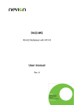
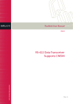
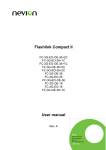
Flashlink Compact FC-3G-EO-14 FC-3G-EO-28 FC-3G-OE-14 FC-3G-OE-28 FC-3G-EO-OE-28 3G/HD/SD-SDI optical/electrical converter User manual Rev. 1 Nevion Europe P.O. Box 1020, 3204 Sandefjord, Norway – Tel: +47 33 48 99 99 – Fax: +47 33 48 99 98 www.nevion.com FC-3G-EO/OE-14/28 Rev. 1 Nevion Support Nevion Europe Nevion USA P.O. Box 1020 3204 Sandefjord, Norway Support phone 1: +47 33 48 99 97 Support phone 2: +47 90 60 99 99 1600 Emerson Avenue Oxnard, CA 93033, USA Toll free North America: (866) 515-0811 Outside North America: +1 (805) 247-8560 E-mail: [email protected] See http://www.nevion.com/support/ for service hours for customer support globally. Revision history Current revision of this document is the uppermost in the table below. Rev. Repl. Date 1 0 2010-12-17 0 A 2010-08-18 A - 2010-05-20 Sign Change description AA/AJM Added Declaration of Conformity. Added description of unlocking options (Ch. 5). AJM Corrected ordering number for SFP-3G-OE-2 and SFP-3G-EO-2-13T. Corrected the operating temperature specification. Updated SFP part number. AJM First release nevion.com | 2 FC-3G-EO/OE-14/28 Rev. 1 Contents Revision history .......................................................................................................... 2 1 Product overview ..................................................................................................... 4 1.1 Product versions .............................................................................................................. 4 2 Specifications .......................................................................................................... 5 2.1 Front view ........................................................................................................................ 7 2.1.1 FC-3G-EO-14 ............................................................................................................... 7 2.1.2 FC-3G-EO-28 ............................................................................................................... 8 2.1.3 FC-3G-OE-14 ............................................................................................................... 9 2.1.4 FC-3G-OE-28 ..............................................................................................................10 2.1.5 FC-3G-EO-OE-28 ........................................................................................................11 2.2 Rear view .......................................................................................................................12 2.2.1 FC-3G-EO-14 ..............................................................................................................12 2.2.2 FC-3G-EO-28 ..............................................................................................................12 2.2.3 FC-3G-OE-14 ..............................................................................................................13 2.2.4 FC-3G-OE-28 ..............................................................................................................13 2.2.5 FC-3G-EO-OE-28 ........................................................................................................14 3 Configuration ......................................................................................................... 15 3.1 Stand alone mode ..........................................................................................................15 3.2 Multicon Gyda mode.......................................................................................................15 3.2.1 Address setting ............................................................................................................15 3.2.2 Multicon Gyda configuration ........................................................................................17 3.2.3 Multicon Gyda information ...........................................................................................19 4 Upgrade firmware .................................................................................................. 20 5 Unlocking options .................................................................................................. 21 6 Nevion SFP ........................................................................................................... 23 General environmental requirements for Nevion equipment..................................... 24 Product Warranty ...................................................................................................... 25 Appendix A Materials declaration and recycling information..................................... 26 A.1 Materials declaration ......................................................................................................26 A.2 Recycling information .....................................................................................................26 EC Declaration of Conformity ................................................................................... 27 nevion.com | 3 FC-3G-EO/OE-14/28 Rev. 1 1 Product overview The Flashlink compact is a range of low power, low price and small form factor optical to electrical converters. It can converts up to 28 channels of 3G-SDI in a 1U 19” space. Both EO and OE converters have an SD/HD/3G-SDI reclocker and supports bypass for none broadcast bitrates. The Flashlink Compact can be controlled and monitored by Multicon Gyda or configured to be a standalone converter. The optical is based on Nevion’s hot pluggable SFP modules. The Flashlink Compact is equipped with an extra power inlet for dual power supply redundancy, either from an extra SL-PWR-40 or battery pack. 1.1 Product versions FC-3G-EO-14 14 channel electrical to optical converter FC-3G-EO-28 28 channel electrical to optical converter FC-3G-OE-14 14 channel optical to electrical converter FC-3G-OE-28 28 channel optical to electrical converter FC-3G-EO-OE-28 14 channel electrical to optical converter and 28 channel optical to electrical converter All variants can be delivered with dual power supply and Multicon Gyda control and monitoring as options. The Multicon Gyda option does not include a Multicon Gyda module. It only unlocks the Flashlink Compact to be able to talk to a Multicon Gyda. One option for each Flashlink compact is necessary. nevion.com | 4 FC-3G-EO/OE-14/28 Rev. 1 2 Specifications General Power +15V DC / 26W, max Weight 2.0kg, 2.4kg with dual power Size 1.7” x 19” x 3.1” (H x W x D) 43.4mm x 482.6mm x 80.0mm (H x W x D) Control Options for Multicon Gyda control and status BITE (Built-In Test Equipment) Status LED in front Configurations DIP in front Operating temperature 0 to +30 °C Data rate reclocked: 270, 1485, 1485/1.001, 2970, 2970/1.001 Mbps Data rate non-reclocked: 19.4 to 2970 Mbps Supported standards SD, 270Mbps SMPTE259M HD, 1485Mbps SMPTE292-2008 3G, 2999Mbps SMPTE424M DVB-ASI EN50083-9. Fiber Transmission SMPTE297-2006 Electrical connector, BC IEC 61169-8 Optical SDI input See Nevion SFP datasheets for specification. Optical SDI output See Nevion SFP datasheets for specification. Electrical SDI input Connectors BNC, IEC 61169-8 Impedance 75ohm Cable equalization Automatic; 150m @270Mbps w/Belden 8281 100m @1485Mbps w/Belden 1694A 70m @1485Mbps w/Belden 1694A Input Return loss >15dB, 5-1485MHz >10dB, 1485-2970MHz nevion.com | 5 FC-3G-EO/OE-14/28 Rev. 1 Electrical SDI outputs Connectors BNC, IEC 61169-8 Impedance 75ohm Output signal level 800mV +/- 10% Output signal rise / fall time 20% - 80% - SD, 0.4ns – 1.5ns, <0.5ns rise/fall variation - HD/3G, < 270ps, <100ps rise/fall variation DC-offset 0V +/-0,5 Amplitude overshoot <10% Output return loss >15dB, 5-1485MHz >10dB, 1485-2970MHz nevion.com | 6 FC-3G-EO/OE-14/28 Rev. 1 2.1 Front view 2.1.1 FC-3G-EO-14 Power A indicator: Power B indicator: Gives status on power supply connected to the Power A connector on the back side. Green: Power supply connected Orange: No or none working power supply connected Red: The lower converter is malfunction. Please contact Nevion support for advice. Gives status on power supply connected to the Power A connector on the back side. Green: Power supply connected Orange: No or none working power supply connected Red: The lower converter is malfunction. Please contact Nevion support for advice. 1 to 14 indicators: Gives status on each electrical to optical converter. Green: Valid input signal and reclocker in lock or bypass. Orange: Valid input signal but reclocker not in lock. Red: No valid input signal. No light: No valid Nevion SFP present. DIP 1 to 14: Configures the Flashlink Compact. See chapter 3 for more information. nevion.com | 7 FC-3G-EO/OE-14/28 Rev. 1 2.1.2 FC-3G-EO-28 Power A indicator: Power B indicator: Gives status on power supply connected to the Power A connector on the back side. Green: Power supply connected Orange: No or none working power supply connected Red: The lower converter is malfunction. Please contact Nevion support for advice. Gives status on power supply connected to the Power A connector on the back side. Green: Power supply connected Orange: No or none working power supply connected Red: The lower converter is malfunction. Please contact Nevion support for advice. 1 to 14 indicators: Gives status on each electrical to optical converter. Green: Valid input signal and reclocker in lock or bypass. Orange: Valid input signal but reclocker not in lock. Red: No valid input signal. No light: No valid Nevion SFP present. DIP 1 to 14: Configures the Flashlink Compact. See chapter 3 for more information. nevion.com | 8 FC-3G-EO/OE-14/28 Rev. 1 2.1.3 FC-3G-OE-14 Power A indicator: Power B indicator: Gives status on power supply connected to the Power A connector on the back side. Green: Power supply connected Orange: No or none working power supply connected Red: The lower converter is malfunction. Please contact Nevion support for advice. Gives status on power supply connected to the Power A connector on the back side. Green: Power supply connected Orange: No or none working power supply connected Red: The lower converter is malfunction. Please contact Nevion support for advice. 1 to 14 indicators: Gives status on each optical to electrical converter. Green: Valid input signal and reclocker in lock or bypass. Orange: Valid input signal but reclocker not in lock. Red: No valid input signal. No light: No valid Nevion SFP present. DIP 1 to 14: Configures the Flashlink Compact. See chapter 3 for more information. nevion.com | 9 FC-3G-EO/OE-14/28 Rev. 1 2.1.4 FC-3G-OE-28 Power A indicator: Power B indicator: Gives status on power supply connected to the Power A connector on the back side. Green: Power supply connected Orange: No or none working power supply connected Red: The lower converter is malfunction. Please contact Nevion support for advice. Gives status on power supply connected to the Power A connector on the back side. Green: Power supply connected Orange: No or none working power supply connected Red: The lower converter is malfunction. Please contact Nevion support for advice. 1 to 14 indicators: Gives status on each optical to electrical converter. Green: Valid input signal and reclocker in lock or bypass. Orange: Valid input signal but reclocker not in lock. Red: No valid input signal. No light: No valid Nevion SFP present. DIP 1 to 14: Configures the Flashlink Compact. See chapter 3 for more information. nevion.com | 10 FC-3G-EO/OE-14/28 Rev. 1 2.1.5 FC-3G-EO-OE-28 Power A indicator: Power B indicator: Gives status on power supply connected to the Power A connector on the back side. Green: Power supply connected Orange: No or none working power supply connected Red: The lower converter is malfunction. Please contact Nevion support for advice. Gives status on power supply connected to the Power A connector on the back side. Green: Power supply connected Orange: No or none working power supply connected Red: The lower converter is malfunction. Please contact Nevion support for advice. 1 to 14 indicators: Gives status on each electrical to optical and optical to electrical converter. Green: Valid input signal and reclocker in lock or bypass. Orange: Valid input signal but reclocker not in lock. Red: No valid input signal. No light: No valid Nevion SFP present. DIP 1 to 14: Configures the Flashlink Compact. See chapter 3 for more information. nevion.com | 11 FC-3G-EO/OE-14/28 Rev. 1 2.2 Rear view 2.2.1 FC-3G-EO-14 Earth point: For connection to internal earth bar in 19” BNC: Electrical 3G/HD/SD-SDI inputs. SFP: Cage for fitting dual optical transmitters. Upper RS422: TP45 connector for connection for Multicon Gyda. Lower RS422: TP45 connector for daisy chaining more Flashlink Compact. This must be terminated when not used. Power A: Main DC input connector. Standard 9pin DSUB. Pin 4 is positive voltage and pin 1 is ground. Power B: Spare/redundancy DC input connector. Standard 9pin DSUB. Pin 4 is positive voltage and pin 1 is ground. 2.2.2 FC-3G-EO-28 Earth point: For connection to internal earth bar in 19” Upper BNC: Electrical 3G/HD/SD-SDI inputs. Upper SFP: Cage for fitting dual optical transmitters. Lower BNC: Electrical 3G/HD/SD-SDI inputs. Lower SFP: Cage for fitting dual optical transmitters. Upper RS422: TP45 connector for connection for Multicon Gyda. Lower RS422: TP45 connector for daisy chaining more Flashlink Compact. This must be terminated when not used. Power A: Main DC input connector. Standard 9pin DSUB. Pin 4 is positive voltage and pin 1 is ground. Power B: Spare/redundancy DC input connector. Standard 9pin DSUB. Pin 4 is positive voltage and pin 1 is ground. nevion.com | 12 FC-3G-EO/OE-14/28 Rev. 1 2.2.3 FC-3G-OE-14 Earth point: For connection to internal earth bar in 19” BNC: Electrical 3G/HD/SD-SDI outputs. SFP: Cage for fitting dual optical receivers. Upper RS422: TP45 connector for connection for Multicon Gyda. Lower RS422: TP45 connector for daisy chaining more Flashlink Compact. This must be terminated when not used. Power A: Main DC input connector. Standard 9pin DSUB. Pin 4 is positive voltage and pin 1 is ground. Power B: Spare/redundancy DC input connector. Standard 9pin DSUB. Pin 4 is positive voltage and pin 1 is ground. 2.2.4 FC-3G-OE-28 Earth point: For connection to internal earth bar in 19” Upper BNC: Electrical 3G/HD/SD-SDI outputs. Upper SFP: Cage for fitting dual optical receivers. Lower BNC: Electrical 3G/HD/SD-SDI outputs. Lower SFP: Cage for fitting dual optical receivers. Upper RS422: TP45 connector for connection for Multicon Gyda. Lower RS422: TP45 connector for daisy chaining more Flashlink Compact. This must be terminated when not used. Power A: Main DC input connector. Standard 9pin DSUB. Pin 4 is positive voltage and pin 1 is ground. Power B: Spare/redundancy DC input connector. Standard 9pin DSUB. Pin 4 is positive voltage and pin 1 is ground. nevion.com | 13 FC-3G-EO/OE-14/28 Rev. 1 2.2.5 FC-3G-EO-OE-28 The optical to electrical is always the upper row and the electrical to optical is always the lower row. Earth point: For connection to internal earth bar in 19” Upper BNC: Electrical 3G/HD/SD-SDI outputs. Upper SFP: Cage for fitting dual optical receivers. Lower BNC: Electrical 3G/HD/SD-SDI inputs. Lower SFP: Cage for fitting dual optical transmitter. Upper RS422: TP45 connector for connection for Multicon Gyda. Lower RS422: TP45 connector for daisy chaining more Flashlink Compact. This must be terminated when not used. Power A: Main DC input connector. Standard 9pin DSUB. Pin 4 is positive voltage and pin 1 is ground. Power B: Spare/redundancy DC input connector. Standard 9pin DSUB. Pin 4 is positive voltage and pin 1 is ground. nevion.com | 14 FC-3G-EO/OE-14/28 Rev. 1 3 Configuration Flashlink Compact can operate in two modes. Stand alone and Multicon Gyda controlled mode. This setting is set by switch 8 on the front of the Flashlink Compact. If Flashlink Compact does not appear in Multicon Gyda, check that switch 8 is set to on. 3.1 Stand alone mode The Flashlink Compact is configured to transport SD/HD/3G-SDI with reclocked set to auto. Switch 1 to 7 has no function in this mode. 3.2 Multicon Gyda mode In this mode configuration and monitoring can be done by Multicon Gyda. This function also has to be unlocked by the Multicon Gyda options sold separately. See chapter 5 Unlocking options The Flashlink Compact can be seen as a two slot Flashlink frame populated with 14 OE or 14 EO converters. Each slot must be set to a unique sub-rack and slot address. This is done with switch 1 to 7 on the front of the product. In order to ensure proper operation of the system, it is important that no subracks or Flashlink Compact controlled by the same Multicon Gyda have the same address set. 3.2.1 Address setting For communication with Multicon Gyda the addresses on the Flashlink Compact has to be set. Depending on the product one or two unique address has to be set. This is done by the switches in front of the product. The first 3 switches set the sub-rack address: SW1 SW2 SW3 Sub-rack OFF OFF OFF 0 ON OFF OFF 1 OFF ON OFF 2 ON ON OFF 3 OFF OFF ON 4 ON OFF ON 5 OFF ON ON 6 ON ON ON 7 nevion.com | 15 FC-3G-EO/OE-14/28 Rev. 1 The next 4 switches set the slot address: SW4 SW5 SW6 SW7 Slot OFF OFF OFF OFF 1 ON OFF OFF OFF 2 OFF ON OFF OFF 3 ON ON OFF OFF 4 OFF OFF ON OFF 5 ON OFF ON OFF 6 OFF ON ON OFF 7 ON ON ON OFF 8 OFF OFF OFF ON 9 ON OFF OFF ON Not allowed OFF ON OFF ON Not allowed ON ON OFF ON Not allowed OFF OFF ON ON Not allowed ON OFF ON ON Not allowed OFF ON ON ON Not allowed ON ON ON ON Not allowed A power recycling is need after a change in address. . nevion.com | 16 FC-3G-EO/OE-14/28 Rev. 1 3.2.2 Multicon Gyda configuration The Flashlink Compact does not store configuration set from Multicon Gyda. This means that the Flashlink Compact will after a power recycling receive stored parameters from Multicon Gyda. 3.2.2.1 Card label Assigns a name. When the locate is pushed all indicators on front of the Flashlink Compact will flash for 120 seconds, alternative an period can be enter into the sec box. 3.2.2.2 Firmware upgrade Updates the firmware on Flashlink Compact. The firmware file first has to be uploaded to Multicon Gyda by ftp. See user manual on Multicon Gyda for help on uploading. 3.2.2.3 Electrical input For SDI signal set the electrical input to normal. For MADI and other low bitrate none SDI signal set this to EQ bypass. The alarm handling for the electrical input can be turn on or off by the normal and ignore radio button. Also the SNMP alarm trap can be turn on or off by send or ignore radio button. 3.2.2.4 Electrical output Turns on and off the output signal. When in auto mode the state of reclocker controls the output state. If reclocker is in lock then output is on, else output is off. If reclocker is in bypass the output is on. 3.2.2.5 Reclocker For SDI signal set to enable, else set to bypass. Autobypass only works if the reclocker is enabled. With autobypass on the reclocker will set the reclocker in bypass mode when none SDI signal is detected. The alarm handling for the reclocker can be turn on or off by the normal and ignore radio button. Also the SNMP alarm trap can be turn on or off by send or ignore radio button. 3.2.2.6 Optical input No configurable parameters. The alarm handling for the optical input can be turn on or off by the normal and ignore radio button. Also the SNMP alarm trap can be turn on or off by send or ignore radio button. nevion.com | 17 FC-3G-EO/OE-14/28 Rev. 1 3.2.2.7 Optical output Turns on or off the optical output. For safety reason turn off none used optical ports. The alarm handling for the optical output can be turn on or off by the normal and ignore radio button. Also the SNMP alarm trap can be turn on or off by send or ignore radio button. 3.2.2.8 Voltage (15.0) This is the external DC power inlet on the backside of the Flashlink Compact. The alarm handling for the external voltage can be can be turn on or off by the normal and ignore radio button. Also the SNMP alarm trap can be turn on or off by send or ignore radio button. The voltage threshold can also be changes, voltages is in mV. 3.2.2.9 Voltage (3.3) This is the internal voltage in Flashlink Compact. The alarm handling for the external voltage can be can be turn on or off by the normal and ignore radio button. Also the SNMP alarm trap can be turn on or off by send or ignore radio button. The voltage threshold can also be changes, voltages is in mV. 3.2.2.10 Card version This box gives information on the firmware used in the Flashlink compact. Always state this when contacting Nevion support. nevion.com | 18 FC-3G-EO/OE-14/28 Rev. 1 3.2.3 Multicon Gyda information On top of the Multicon Gyda information tab a dynamical picture of the Flashlink Compact is displayed. The red cross will automatically update reflecting the status on the Flashlink Compact. Table below describe the meaning of the red cross: Electrical input: Red cross means no electrical input present. Electrical output: Red cross means reclocker not in lock or electrical output turned off. Optical input: Read cross means no optical input present or no SFP present. Optical output: Red cross means reclocker not in lock or no SFP present. nevion.com | 19 FC-3G-EO/OE-14/28 Rev. 1 4 Upgrade firmware For upgrading the firmware the switch 8 has to be set to on; Multicon Gyda mode. The address also has to be set correctly according to chapter 3.2.1. See Multicon Gyda manual for instructions on upgrading Flashlink card. The Multicon Gyda option is not needed for firmware upgrade nevion.com | 20 FC-3G-EO/OE-14/28 Rev. 1 5 Unlocking options Only available from firmware version 1.2.7. For unlocking options Nevion needs the serial number of the card/product. This can be found in the configuration pan in Multicon Gyda or by sending the “?” or “optn 0” command in the debug terminal. See screen shots from Multicon Gyda below. To check which options are installed the “optn 0” command in Multicon Gyda debug terminal can be used. Below is a screen shoot from two cards, one with Gyda enabled and one without Gyda options. nevion.com | 21 FC-3G-EO/OE-14/28 Rev. 1 The received unlock key from Nevion has to be sent to the card using the debug terminal in Multicon Gyda. An unlock key consist of the command “optn 0” followd by six 10 digit keys. optn 0 1836889408 141478916 1458913010 806395448 859561046 154663979 After sending this key to the card the card will response with status of options. See screen shot below. nevion.com | 22 FC-3G-EO/OE-14/28 Rev. 1 6 Nevion SFP A list of valid Nevion SFP for the Flashlink Compact with Nevion ordering number.: Ordering code Name Description 19145 SFP-3G-OE-2 Dual receiver SFP 19144 SFP-3G-EO-2-13T Dual 1310 nm transmitter SFP 19244 SFP-3G-EO-2-C1310/C1550 Dual Transmitter LC, 1310/1550nm 19245 SFP-3G-EO-2-C1270/C1290 Dual Transmitter LC, 1270/1290nm 19246 SFP-3G-EO-2-C1310/C1330 Dual Transmitter LC, 1310/1330nm 19247 SFP-3G-EO-2-C1350/C1370 Dual Transmitter LC, 1350/1370nm 19248 SFP-3G-EO-2-C1390/C1410 Dual Transmitter LC, 1390/1410nm 19249 SFP-3G-EO-2-C1430/C1450 Dual Transmitter LC, 1430/1450nm 19250 SFP-3G-EO-2-C1470/C1490 Dual Transmitter LC, 1470/1490nm 19251 SFP-3G-EO-2-C1510/C1530 Dual Transmitter LC, 1510/1530nm 19252 SFP-3G-EO-2-C1550/C1570 Dual Transmitter LC, 1550/1570nm 19253 SFP-3G-EO-2-C1590/C1610 Dual Transmitter LC, 1590/1610nm Changing SFP can be done without removing power nevion.com | 23 FC-3G-EO/OE-14/28 Rev. 1 General environmental requirements for Nevion equipment 1. 2. - The equipment will meet the guaranteed performance specification under the following environmental conditions: Operating room temperature range: 0°C to 30°C Operating relative humidity range: <90% (non-condensing) The equipment will operate without damage under the following environmental conditions: Temperature range: -10°C to 40°C Relative humidity range: <95% (non-condensing) nevion.com | 24 FC-3G-EO/OE-14/28 Rev. 1 Product Warranty The warranty terms and conditions for the product(s) covered by this manual follow the General Sales Conditions by Nevion, which are available on the company web site: www.nevion.com nevion.com | 25 FC-3G-EO/OE-14/28 Rev. 1 Appendix A Materials declaration and recycling information A.1 Materials declaration For product sold into China after 1st March 2007, we comply with the “Administrative Measure on the Control of Pollution by Electronic Information Products”. In the first stage of this legislation, content of six hazardous materials has to be declared. The table below shows the required information. Toxic or hazardous substances and elements 組成名稱 Part Name 鉛 汞 镉 六价铬 多溴联苯 Lead Mercury Cadmium Hexavalent Polybrominated (Pb) (Hg) (Cd) Chromium biphenyls (Cr(VI)) (PBB) 多溴二苯醚 Polybrominated diphenyl ethers (PBDE) FC-3G-EO/OE-14/28 O O O O O O SL-PWR-40 O O O O O O O: Indicates that this toxic or hazardous substance contained in all of the homogeneous materials for this part is below the limit requirement in SJ/T11363-2006. X: Indicates that this toxic or hazardous substance contained in at least one of the homogeneous materials used for this part is above the limit requirement in SJ/T11363-2006. This is indicated by the product marking: A.2 Recycling information Nevion provides assistance to customers and recyclers through our web site http://www.nevion.com/. Please contact Nevion’s Customer Support for assistance with recycling if this site does not show the information you require. Where it is not possible to return the product to Nevion or its agents for recycling, the following general information may be of assistance: Before attempting disassembly, ensure the product is completely disconnected from power and signal connections. All major parts are marked or labeled to show their material content. Depending on the date of manufacture, this product may contain lead in solder. Some circuit boards may contain battery-backed memory devices. nevion.com | 26 EC Declaration of Conformity MANUFACTURER AUTHORIZED REPRESENTATIVE (Established within the EEA) Nevion Europe AS P.O. Box 1020, 3204 Sandefjord, Norway Not applicable MODEL NUMBER(S) FC-3G-EO-14 FC-3G-EO-28 FC-3G-OE-14 FC-3G-OE-28 FC-3G-EO-OE-28 DESCRIPTION 3G/HD/SD-SDI optical/electrical converter DIRECTIVES this equipment complies with Low voltage (EU Directive 2006/95/EC) EMC (EU Directive 2004/108/EC) RoHS (EU Directive 2002/95/EC) 1 China RoHS WEEE (EU Directive 2002/96/EC) REACH HARMONISED STANDARDS applied in order to verify compliance with Directive(s) EN 55103-1:2010 EN 55103-2:2010 TEST REPORTS ISSUED BY Notified/Competent Body Report no: - - TECHNICAL CONSTRUCTION FILE NO Not applicable YEAR WHICH THE CE-MARK WAS AFFIXED 2010 TEST AUTHORIZED SIGNATORY MANUFACTURER AUTHORIZED REPRESENTATIVE (Established within EEA) Date of Issue 2010-12-17 Place of Issue Not applicable 1 Name Thomas Øhrbom Position QA Director, Nevion Europe (authorized signature) Sandefjord, Norway Administration on the Control of Pollution Caused by Electronic Information Products Nevion Europe P.O. Box 1020, 3204 Sandefjord, Norway – Tel: +47 33 48 99 99 – Fax: +47 33 48 99 98 www.nevion.com