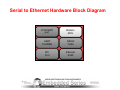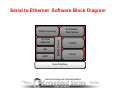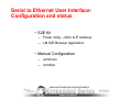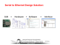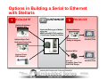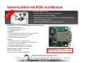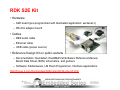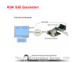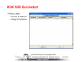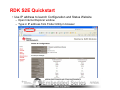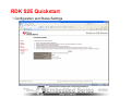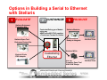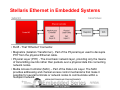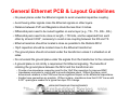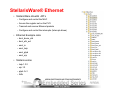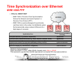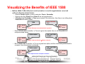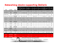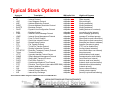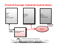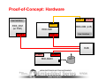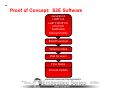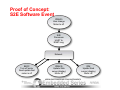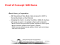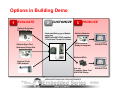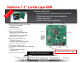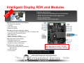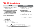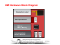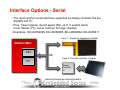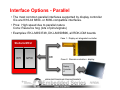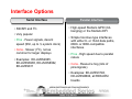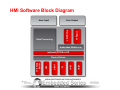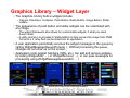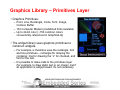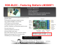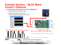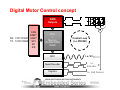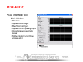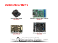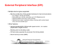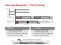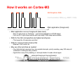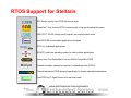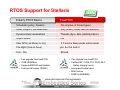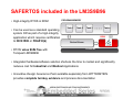
1
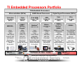
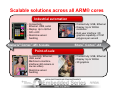
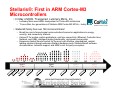
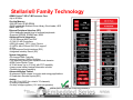
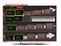
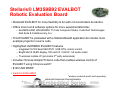
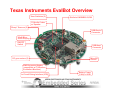
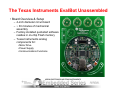
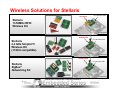
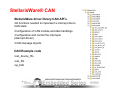
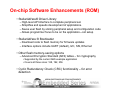
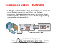
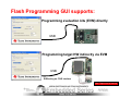
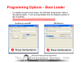
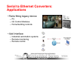
® Stellaris MCU Day Serial to Ethernet: Solutions ready to implement Stellaris® ARM® Cortex™-M3 Microcontroller Solutions Embedded Series 2011 Winner Stellaris Day Agenda 1 2 3 4 5 6 7 Stellaris Family StellarisWare® Serial to Ethernet Converter Designing a Serial to Ethernet Converter S2E RDK Overview Industrial Control Demo Overview Proof of Concept: S2E Converter Demo TI Embedded Processors Portfolio TI Embedded Processors Microcontrollers (MCUs) 16-bit ultralow power MCUs 32-bit real-time MCUs MSP430™ C2000™ Delfino™ Piccolo™ Up to 25 MHz Flash 1 KB to 256 KB 40MHz 300 MHz Flash, RAM 16 KB to 512 Analog I/O, ADC LCD, USB, RF PWM, ADC, CAN, SPI, I2C Measurement, Sensing, General Purpose $0.49 to $9.00 Motor Control, Digital Power, Lighting, Ren. Energy $1.50 to $20.00 ARM®-Based Processors 32-bit ARM Cortex™-M3 MCUs Stellaris ® ARM Cortex™-M3 ® Up to 80 MHz Flash 8 KB to 256 KB USB, ENET MAC+PHY CAN, ADC, PWM, SPI Connectivity, Security, Motion Control, HMI, Industrial Automation $1.00 to $8.00 Digital Signal Processors (DSPs) ARM Cortex-A8 MPUs Highperformance DSPs Ultra Low power DSP Sitara™ C6000™ DaVinci™ C5000™ ARM® Cortex™-A8 & ARM9 OMAP™ 300MHz to >1GHz Cache, RAM, ROM 300MHz to >1Ghz +Accelerator Cache RAM, ROM Up to 300 MHz +Accelerator Up to 320KB RAM Up to 128KB ROM USB, CAN, PCIe, EMAC USB, ENET, PCIe, SATA, SPI USB, ADC McBSP, SPI, I2C Industrial computing, POS & portable data terminals $5.00 to $20.00 Test & Meas., Video, audio, security, imaging, infrastructure $5.00 to $200.00 Audio, Voice Medical, Biometrics Software & Dev. Tools $3.00 to $10.00 Scalable solutions across all ARM® cores Industrial automation • Connectivity: Ethernet, USB, serial • Display: Up to QVGA 320 x 240 • Real-time sensor handling Stellaris® Cortex™-M3 Scalable • Connectivity: USB, Ethernet • Display: Up to WXGA resolution • Rich user interface: 3D graphics capability of 10M polygons per second Sitara™ Cortex™-A8 Point-of-sale • Connectivity: Ethernet, USB, serial • Machine-to-machine interface (still camera or low res video) • Real-time sensor handling • Connectivity: USB, Ethernet • Display: Up to WXGA • 3D graphics What is ARM® Cortex™-M3? • The Cortex family of ARM processors provides a range of solutions optimized around specific market applications across the full performance spectrum. • Cortex underlines ARM's strategy of aligning technology around specific market applications and performance requirements. • The ARM Cortex family is comprised of three series, which all implement the Thumb-2 instruction set to address the increasing performance and cost demands of various markets: – ARM Cortex-A Series, • Applications processors for complex OS and user applications • Supports the ARM, Thumb and Thumb-2 instruction sets – ARM Cortex-R Series • Embedded processors for real-time systems • Supports the ARM, Thumb, and Thumb-2 instruction sets – ARM Cortex-M Series • Deeply embedded processors • Optimized for cost-sensitive applications • Supports the Thumb-2 instruction set only Note: • ARM Code 32-bit instructions / 32-bit data • Thumb Code 16-bit instructions / 32-bit data • Thumb-2 Code mostly 16-bit & some 32-bit (25% Faster, 26% Smaller) Did You Know? Texas Instruments is the lead partner for ARM Cortex A8, R4, M3, and M4! Stellaris®: First in ARM Cortex-M3 Microcontrollers • In May of 2009, TI acquired Luminary Micro, Inc. – Luminary Micro was ARM’s lead partner for Cortex-M3 architecture – TI now offers four generations of Stellaris ARM Cortex-M3 MCUs – today! • Stellaris® family has over 160 microcontrollers! – Broad line card of mixed-signal microcontrollers focused on applications in energy, security, and connectivity markets – Unique IP for motion control applications, real time connectivity (Ethernet, Controller Area Network, and USB), intelligent analog functionality, and power conservation – Experience fastest time-to-market for the most cost effective, standardized, marketleading solutions through extensive Stellaris hardware tools, StellarisWare® software, documentation, technical support, and ARM’s vast 3rd party ecosystem 2 6 24 19 51 Stellaris 1st Gen 06 06 06 20 20 20 L Y AR MA JU M 85 128 104 Stellaris 2ndGen B FE 07 20 N JU 07 20 P SE 07 20 138 167 Stellaris 3rd Gen C DE 07 20 R AP Stellaris 4th Gen 08 20 M AR 09 20 N JU 11 20 Stellaris® Family Technology ARM® Cortex™-M3 v7-M Processor Core •Up to 80 MHz On-chip Memory •256 KB Flash; 96 KB SRAM •ROM loaded with Stellaris Driver Library, BootLoader, AES tables, and CRC External Peripheral Interface (EPI) •32-bit dedicated parallel bus for external peripherals •Supports SDRAM, SRAM/Flash, M2M Advanced Serial Integration •10/100 Ethernet MAC and PHY •3 CAN 2.0 A/B Controllers •USB (full speed) OTG / Host / Device •3 UARTs with IrDA and ISO 7816 support* •2 I2Cs •2 Synchronous Serial Interfaces (SSI) •Integrated Interchip Sound (I2S) System Integration •32-channel DMA Controller •Internal Precision 16MHz Oscillator •Two watchdog timers with separate clock domains •ARM Cortex Systick Timer •4 32-bit timers (up to 8 16-bit) with RTC capability •Lower-power battery-backed hibernation module •Flexible pin-muxing capability Advanced Motion Control •8 advanced PWM outputs for motion and energy applications •2 Quadrature Encoder Inputs (QEI) Analog •2x 8-ch 10-bit ADC (for a total of 16 channels) •3 analog comparators •On-chip voltage regulator (1.2V internal operation) Stellaris® Roadmap Production Sampling Development ARM® Cortex™-M3 ARM Cortex –M3 ARM Cortex -M4F Ethernet LM3S9xxx • 128-256KB flash • CAN & motion control • 64- & 100-pin pkg LM3S6xxx General MCU USB • 64-256KB flash • Motion control • 64- & 100-pin pkg LM3S3xxx/5xxx • 16-256KB flash • CAN & motion control • 64- & 100-pin pkg LM3S1xx/3xx LM3S6xx/8xx • 8-64KB flash • Motion control • 48-pin pkg TI Information Selective Disclosure LM4F29B/29C LM3S9xxx • 384-512KB flash • CAN & motion control • 64- & 100-pin pkg LM4F291/294 • 128KB to 2MB flash • Motion control • 64-, 100-, 144-pin LM4F191/194 • 128K to 2MB flash • 64-,100-, 144-pin • • • • 128KB to 2MB flash Encryption/tamper Motion control 64-, 100-, 144-pin LM3S8xxx • 64-256KB flash • CAN & Motion control • 64- & 100-pin pkg Note: All devices include mix of timers, UART, I2C, SPI, USB, I2S, EPI, Ethernet, CAN, PWM, ADCs, DMA. Complete peripheral set not shown for each device. LM4F230/1/2/4 LM4F130/1/2/4 • 32KB-2MB flash • 64-, 100-, 144-pin LM3S1xxx2xxx • 16-256KB flash • CAN & motion control • 64- & 100-pin pkg • 32KB-2MB flash • Motion control • 64-, 100-, 144-pin LM4F110/1/2/4 • 32KB-2MB flash • 64-, 100-, 144-pin LM4F13A/B/C • 128KB-2MB flash • Encryption/tamper • 64-, 100-, 144-pin LM4F11A/B/C • 128KB-2MB flash • Encryption/tamper • 64-, 100-, 144-pin LM4F23B/23C • • • • 128KB-2MB flash Encryption/tamper Motion control 64-, 100-, 144-pin The Stellaris Full-Solution Approach Fully Integrated Stellaris MCUs Production-ready Modules • ARM Cortex-M3 core with single-cycle Flash • Advanced motion control • Integrated deterministic connectivity • Easy adoption / learning curve through 10-min out-of-the-box evaluation kits • Customizable modules for drop-in implementation • Multiple motors supported • Multiple connectivity options • Copy-exactly with open-tooled HW and SW Power, Motor Control, Hall, Analog Stellaris QEI 10/100 CAN Ethernet USB Complete Open-tooled RDKs Proof-of-Concept • Open-tooled HW/SW Reference Design Kits • Motor included for out-of-the-box demonstration • Fully documented, available for download, and in stock • Stellaris MCUs / Modules • Putting our motion control to the test before you do. End-to-End Solution Source Files Royalty-Free Schematics Placement Bill of Materials Gerbers Motor App and StellarisWare® Source Control / Config GUI Stellaris® Evaluation Kits • Start in 10 minutes or less • Evaluation board packages includes: – – – – – EK-LM3S811 Low pin count 49 USD Cables A choice of evaluation tools suites for popular development tools Documentation (QuickStart guide, User’s guide, …) StellarisWare® software Applications notes EK-LM3S1968 High pin count 59 USD EK-LM3S2965 CAN Functionality 79 USD EK-LM3S3748 USB Host/Device 109 USD EK-LM3S6965 EK-LM3S8962 Ethernet MAC+PHY Ethernet+CAN 69 USD 89 USD EK-LM3S9B90 EK-LM3S9B92 Ethernet+USB OTG Ethernet+OTG+MC 99 USD 99 USD • Function both as an evaluation platform and as a serial in-circuit debug interface for any Stellaris microcontroller-based target board Stellaris Reference Design Kits • Speed to market with rapid evaluation • Reference design kit includes: • • • • • RDK_IDM Landscape touch screen 219 USD Motors, adapter, cables Design files – layout, BOM’s, schematic Kit User Guide Documentation StellarisWare® software GUI interface firmware RDK_IDM_SBC Single board touch screen 299 USD RDK_IDM Touch-screen + POE 219 USD RDK_ACIM AC Induction Motor 379 USD RDK_STEPPER Stepper motor 199 USD RDK_S2E Serial –to -Ethernet 139 USD • RDK’s are complete design solution, all open-tooling RDK_BDC CAN + BDC Motor 199 USD RDK _BLDC CAN + Ethernet + BLDC Motor 219 USD EVALBOT: Educating the MCU market Stellaris® LM3S9B92 EVALBOT Robotic Evaluation Board • Stellaris® EVALBOT for more flexibility & fun with microcontrollers & robotics • Offers more tool & software options for more experimentation/dev – Keil MDK-ARM, IAR EWARM, TI Code Composer Studio, Code Red Technologies Red Suite & CodeSourcery G++ • This EVALBOT is preloaded with a StellarisWare® application & includes more example projects in source code • Highlighted LM3S9B92 EVALBOT features – Integrated 10/100 Enet MAC/PHY, USB OTG, motion control – Bright 96x16 OLED display, SD card I/F, CAN I/F, I2S audio codec – TI wireless module I/F (promotes 3rd party extensions) • Includes Chronos-SimpliciTI demo code that enables wireless control of EVALBOT using Chronos watch* • $149 USD MSRP • www.ti.com/evalbot *wireless module & watch sold separately Texas Instruments EvalBot Overview User Switches (2) Stellaris LM3S9B92-IQC80 I²S Audio Codec w/ Speaker “Bump” Sensors (2) USB-Device Connector 96x16 Blue OLED Display ON/OFF Switch DC gear-motors (2) USB-Host Connector MicroSD Socket EM2 Expansion Header (compatible w/ TI Wireless Evaluation Modules) In-Circuit Debug Interface (ICDI) Battery Power (3 AA) or USB The Texas Instruments EvalBot Unassembled • Board Overview & Setup – 4-inch diameter circuit board – ~ 30 minutes of mechanical assembly – Factory-installed quickstart software resides in on-chip Flash memory – Texas Instruments analog components for: • Motor Drive • Power Supply • Communications Functions Wireless Kit for Evalbot: Chronos Remote Control & SmartRF®04 EVALBOT CC1101EMK868-915 eZ430-Chronos Wireless Solutions for Stellaris TRF7960TB DK-LM3S9B96-EM2 Stellaris 13.56MHz RFID Wireless Kit DK-LM3S9B96 DK-EM2-2500S DK-LM3S9B96-EM2 Stellaris 2.4 GHz SimpliciTI Wireless Kit (<1GHz compatible) DK-LM3S9B96 DK-EM2-2520Z DK-LM3S9B96-EM2 Stellaris ZigBee® Networking Kit DK-LM3S9B96 TI Confidential – NDA Restrictions Stellaris Day Agenda 1 2 3 4 5 6 7 Stellaris Family StellarisWare® Serial to Ethernet Converter Designing a Serial to Ethernet Converter S2E RDK Overview Industrial Control Demo Overview Proof of Concept: S2E Converter Demo StellarisWare® • Free license and royalty-free source code: – Peripheral Driver Library – Graphics Library – USB Library – Boot Loader – IEC 60730 Library – Code examples for each kit – Supports different compilers and IDEs • TI CCS, Keil, IAR, Code Red, CodeSourcery G++ Enabling our customers with the ability to rapidly develop and deploy their products at competitive costs yielding a higher overall value for the Stellaris solution! Stellaris® Peripheral Driver Library • High-level API interface to complete peripheral set • Free license and royalty-free use • Simplifies and speeds development of applications • Available as object library and as source code • Works with all supported IDEs – TI CCS, Keil, IAR, Code Red, CodeSourcery G++ • Driver library functions are preprogrammed in ROM on select Stellaris MCUs StellarisWare® CAN StellarisWare driver library CAN API’s •All functions needed to implement a interrupt driven CAN stack •Configuration of CAN module and data handlings •Configuration and control the interrupts (interrupt-driven) •CAN message objects CAN Example code •can_device_fifo •can_fifo •qs_bldc On-chip Software Enhancements (ROM) • StellarisWare® Driver Library – High-level API interface to complete peripheral set. – Simplifies and speeds development of applications. – Saves user flash by storing peripheral setup and configuration code – Allows programmer focus to be on the application—not setup • StellarisWare ® Bootloader – Download code to flash memory for firmware updates – Interface options include UART (default), I2C, SSI, Ethernet • Other flash memory-saving options – Advanced Encryption Standard (AES) tables – for cryptography • Supported by the current AES example application • Covers all three sizes: 128, 192, 256 • Cyclic Redundancy Check (CRC) functionality – for error detection StellarisWare® In-System Programming Options • Stellaris Serial Flash Loader – Small piece of code that allows programming of the flash without the need for a debugger interface – Stellaris MCUs without a ROM ship with this pre-loaded in flash – Interface options include UART or SSI – TI supplies a Windows®-based application (GUI or command line) that makes full use of all commands supported by the serial flash loader (LMflash.exe) • Stellaris Boot Loader – Small piece of code that can be programmed at the beginning of flash to act as an application loader – Also used as an update mechanism for an application running on a Stellaris microcontroller – Interface options include UART (default), I2C, SSI, Ethernet, USB – Included in the Stellaris Peripheral Driver Library with full applications examples – Preloaded in ROM on select Stellaris Microcontrollers StellarisWare® Serial Flash Programming GUI • LM Flash Programming GUI – Simple graphical user interface – Support for all Evaluation Kits – Key features include: • Program • Verify • Erase • Read memory • Available now http://focus.ti.com/docs/toolsw/folders/print/lmflashprogrammer.html Programming Options – JTAG/SWD • If debug is needed, or a flash image is erased you can always use the JTAG/SWD interface to load a binary into the flash. • Remember, Stellaris evaluation kits can act as In-Circuit Debug Interfaces (ICDIs), meaning you can use them to program/debug other boards, such as the RDKs. Flash Programming GUI supports: Programming evaluation kits (EVM) directly USB Programming target HW indirectly via EVM USB EVM acting as JTAG interface Note: Note: Target Target must must be be powered powered Programming Options – Boot Loader • To update using the boot loader, the LM Flash Programmer utility is the easiest option. It can be downloaded from the Stellaris section of the TI website. http://focus.ti.com/docs/toolsw/folders/print/lmflashprogrammer.html No Ethernet, use UART With Ethernet Stellaris Day Agenda 1 2 3 4 5 6 7 Stellaris Family StellarisWare® Serial to Ethernet Converter Designing a Serial to Ethernet Converter S2E RDK Overview Industrial Control Demo Overview Proof of Concept: S2E Converter Demo Serial to Ethernet Converters: Applications • Retro fitting legacy device – PC – I/O Control Modules – Home/building controls • Add Interface – Industrial automation systems – Remote monitoring – Remote control Serial to Ethernet Converters: Features • General Features – RS232 Port – 10/100Mbps Ethernet w/ auto detect – Auto MDI/MDIX cross-over correction – Network Management Interface – Virtual COM software – Selectable baud rates – Programmable web server Stellaris Day Agenda 1 2 3 4 5 6 7 Stellaris Family StellarisWare® Serial to Ethernet Converter Designing a Serial to Ethernet Converter S2E RDK Overview Industrial Control Demo Overview Proof of Concept: S2E Converter Demo Designing a Serial to Ethernet Converter • Typical design considerations – Hardware • MCU: embedded Ethernet + UART • Connection ports: RS232 + RJ45 • Consider other comms: SPI, I/O – Software • Code for MCU to configure and drive embedded Ethernet, UART, and perform data conversion • Web server with TCP/IP stack • Interface for configuration and status Serial to Ethernet Hardware Block Diagram JTAG/SWD JTAG/SWD port port Stellaris Stellaris MCU MCU UART UART Port/DB9 Port/DB9 RS232 RS232 Tx/Rx Tx/Rx SPI SPI Port Port Ethernet Ethernet RJ45 RJ45 Communications: Serial, Ethernet, USB Serial to Ethernet Software Block Diagram Data Data Processing Processing Embedded Embedded Web Web Server Server 10/100M 10/100M Ethernet Ethernet TCP/IP TCP/IP SSI SSI Telnet Telnet UART UART User User Interface Interface Serial to Ethernet User Interface: Configuration and status • S2E Kit – Finder Utility – MAC & IP Address – LM S2E Browser Application • Manual Configuration – com0com – com2tcp Serial to Ethernet Design Solution: S2E = Hardware + Software + Interface Options in Building a Serial to Ethernet with Stellaris 1 EVALUATE 2 CUSTOMIZE 3 PRODUCE Stellaris Quickstart Evaluation Kits Customize/Debug your Module using any ARM Cortex-M3 JTAG emulator + Tools from Trusted 3rd Parties Stellaris Open-Tool Reference Design Kits Stellaris Modules Off-the-Shelf & Ready-to-Integrate PRODUCTION Stellaris MCUs 10-pin to 20-pin JTAG Adapter Use our Complete Open-Tool HW & SW Design PRODUCTION Stellaris Day Agenda 1 2 3 4 5 6 7 Stellaris Family StellarisWare® Serial to Ethernet Converter Designing a Serial to Ethernet Converter S2E RDK Overview Industrial Control Demo Overview Proof of Concept: S2E Converter Demo Serial-to-Ethernet RDK and Module E S2 K RD 39 $1 Example applications: • SCADA Remote Terminal Units (RTUs) • Electronic Flow Meters (EFMs) • Medical Point-of-Care and Retail Point-of-Sales Machines • CCTV RS-232 Recorders • RS-232 Stepper Motor Controller Systems LM3S6432 in a 10 x 10 mm BGA package for reduced board size 10/100 Mbit Ethernet port - Auto MDI/MDIX cross-over correction - Traffic and link indicators Serial ports - UART0 has RS232 levels, transceiver runs at up to 230.4 K baud UART1 has CMOS/TTL levels, can run at 1.0 M baud UART ports include RTS/CTS for flow control Both ports can be used simultaneously Software - IP configuration with static IP address or DHCP Telnet server for access to serial port (VCP software included) Web server for module configuration Universal plug and play (uPnP) for device discovery Telnet client for Ethernet-based serial port extender Module supports 5 V and 3.3 V supplies Multiple mounting options JTAG port pads for factory programming RDK-S2E resale: 139 USD MDL-S2E single unit resale: 49 USD RDK S2E Kit • Hardware – S2E board (pre-programmed with Quickstart application: ser2enet.c) – RS-232 adaptor board • Cables – DB9 serial cable – Ethernet cable – USB cable (power source) • Reference Design Kit on public website – Documentation: Quickstart, ReadMeFirst,Software Reference Manual, Board Data Sheet, BOM, schematics, and gerbers – Software: Stellarisware, LM Flash Programmer, Interface applications http://focus.ti.com/docs/toolsw/folders/print/rdk-s2e-cd.html RDK S2E Quickstart Connect and power RDK S2E Quickstart • Finder Utility – Get the IP address – Using PnP protocol RDK S2E Quickstart • Use IP address to launch Configuration and Status Website – Open Internet Explorer window – Type in IP address from Finder Utility in browser RDK S2E Quickstart • Configuration and Status Settings Options in Building a Serial to Ethernet with Stellaris 1 EVALUATE 2 CUSTOMIZE 3 PRODUCE Stellaris Quickstart Evaluation Kits Customize/Debug your Module using any ARM Cortex-M3 JTAG emulator + Tools from Trusted 3rd Parties Off-the-Shelf & Ready-to-Integrate Stellaris Open-Tool Reference Design Kits 10-pin to 20-pin JTAG Adapter Stellaris Modules Customizing Ethernet PRODUCTION Stellaris MCUs Use our Complete Open-Tool HW & SW Design PRODUCTION Stellaris Ethernet in Embedded Systems • RJ45 - That “Ethernet” Connector. • Magnetics (Isolation Transformer) - Part of the Physical layer used to decouple PHY from the physical Ethernet cable. • Physical Layer (PHY) - The most basic network layer, providing only the means of transmitting raw bits rather than packets over a physical data link connecting network nodes. • Media Access Controller (MAC) – Part of the Data Link Layer. The MAC provides addressing and channel access control mechanisms that make it possible for several terminals or network nodes to communicate within a multipoint network. OSI (Open System Interconnect) Model • OSI defines a set of rules to enable computers to communicate over a network. • It specifies how data is packaged, addressed, and routed to the right destination. Application/Presentation/Session Layers: Higher layer protocols provide the user interface to the network. Transport Layer: concerned with error-free, in sequence data delivery with or without loss or duplication. Examples: TCP/IP, UDP Network/Internet Layer: provides for the raw transfer of information between end systems Data Link Layer: concerned with error detection and control. The MAC (media access controller hardware) is part of this layer. Physical Layer: The physical interface between devices, transport media (e.g., twisted pair), bit stream protocol, electrical representation of bits. The PHY hardware is part of this layer. Ethernet Hardware: Simple Hardware Design *full schematic in Stellaris LM3S8962 Evaluation Board User’s Manual General Ethernet PCB & Layout Guidelines • No power planes under the Ethernet signals to avoid unwanted capacitive coupling. • Avoid having other signals cross the Ethernet signals on other layers. • Distance between PHY and Magnetics should be less than 2 inches. • Differential pairs need to be routed together on same layer (e.g., TX+, TX-, RX+, RX-). • Differential pairs need to be close in length, < 700 mils, and be separated from each other by at least 0.050”, necessary to avoid cross-coupling between the RX and TX. • Ethernet resistors should be located a close as possible to the Stellaris MCU. • 10pF capacitors should be located close to the Ethernet transformer. • The ground plane should not extend under the transformer unless it is shielded on all sides. • Do not extend the ground plane under the signals from the transformer to the connector. • A ground plane is not strictly a requirement for Ethernet signaling. The benefits of retaining the ground plane between the MCU and the transformer are: – Provide a low-impedance connection point for the 10pF filter capacitors for improved EMC – Impedances are easier to control with a ground-reference plane. Without the plane, small dimensional variations in the PCB have a more significant impact on the differential impendance. – Smaller trace geometries are possible. Without a plane, simulations show that 0.023” traces with 0.007” spacing are needed for a typical two-layer FR-4 design. StellarisWare® Ethernet • StellarisWare driverlib API’s – Configure and control the MAC – Access the register set on the PHY – Transmit and receive Ethernet packets – Configure and control the interrupts (Interrupt-driven) • Ethernet Example code – boot_demo_eth – boot_eth_ext – enet_io – enet_lwip – enet_ptpd – enet_uip • Stellaris extras – lwip-1.3.2 – uip-1.0 – ptpd-1rc1 – fatfs Time Synchronization over Ethernet IEEE-1588 PTP • What is IEEE1588? – IEEE 1588 is “Precision Clock Synchronization Protocol for Network and Control Systems” or Precision Time Protocol (PTP) – IEEE 1588 is a protocol designed to synchronize real-time clocks in the nodes of a distributed system that communicate using a network (Ethernet) at a high degree of accuracy Application Area Low speed sensors (e.g. pressure, temperature) Common electro-mechanical devices (e.g. relays, breakers, solenoids, valves) General automation (e.g. materials handling, chemical processing) Precise motion control (e.g. high speed packaging, printing, robotics) High speed electrical devices (e.g. synchrophasor measurements) Electronic ranging (e.g. fault detection, triangulation) Stellaris implementation: Required synchronization accuracy Milliseconds Milliseconds Milliseconds A few microseconds Microseconds Sub microsecond Open source lwIP + PTPd : within 500nS of master clock, jitter +/- 500nS This represents a greater than tenfold improvement over typical SW-only implementations Visualizing the Benefits of IEEE 1588 • Before IEEE 1588, Ethernet communication in control applications occurred without absolute determinism: – Assume Sender sends a control instruction Turn to Controller – Assume also that Clock S and Clock C are not synchronized – If Sender asks Controller to Turn upon receipt of the instruction, then there is no telling when Controller will receive Turn. TURN (some ?? time later) “Ok!” Clock S Controller Sender Uh-oh! Ethernet is non-deterministic by nature. Clock C – Even if Sender asks Controller to Turn at a given time alpha, there is still the problem of unsynchronized clocks. “TURN at alpha!” “Ok! I will TURN at alpha.” Clock S Controller Sender Uh-oh! Alpha on Clock S Alpha on Clock C. Clock C – But if Sender asks Controller to Turn at a given time alpha, and the clocks are synchronized to a master, then determinism is achieved. “TURN at alpha!” “Ok! I will TURN at alpha.” Clock S Controller Sender Yes! Alpha on Clock S = Alpha on Clock C. Clock C TCP/IP Communications Stacks for Stellaris Micriμm μC/TCP-IP Express Logic NetX™ TCP/IP protocol stack CMX-MicroNet™ protocol stacks InterNiche TCP/IP NicheStack™, NicheLITE™, and add-on modules such as HTTP, SNMP, and security protocols EtherNet/IP™ protocol stacks FreeRTOS.org Open-Source µIP Embedded web server µIP Open source TCP/IP stack for small footprint embedded systems lwIP Open source light-weight implementation of the TCP/IP stack for small RAM embedded systems IEEE 1588 PTP (Precision Time Protocol) SEVENSTAX TCP/IP Protocol Stack Networking stacks supporting Stellaris List is subject to change Typical Stack Options – – – – – – – – – – – – – – – – – – – – – – – – – – – – Acronym TCP IP UDP ARP RARP BOOTP DHCP BSD ICMP IGMP PPP SLIP DNS FTP TFTP RIP RTP/RTCP Telnet HTTP SNMP SMTP POP3 SNTP PTP* NAT SSL IPSec IKE Translation - Transmission Control Protocol - Internet Protocol - User Datagram Protocol - Address Resolution Protocol - Reverse Address Resolution Protocol - Bootstrap Protocol - Dynamic Host Configuration Protocol - Berkeley Socket - Internet Control Message Protocol - Internet Group Management Protocol - Point-To-Point Protocol - Serial Line Internet Protocol - Domain Name System - File Transfer Protocol - Trivial File Transfer Protocol - Routing Information Protocol - Real-time Transport (Control) Protocol - Terminal Emulation - Hypertext transfer Protocol Server - Simple Network Management Protocol - Simple Mail Transport Protocol - Post Office Protocol-3 - Synchronized Network Time Protocol - Precision Time Protocol (also called IEEE1588) - Network Address Translation - Secure Sockets Layer - Internet Protocol Security - Internet Key Exchange *Several Stellaris MCUs integrate hardware assistance for IEEE1588 PTP. Wikipedia Link wikipedia Link wikipedia Link wikipedia Link wikipedia Link wikipedia Link wikipedia Link wikipedia Link wikipedia Link wikipedia Link wikipedia Link wikipedia Link wikipedia Link wikipedia Link wikipedia Link wikipedia Link wikipedia Link wikipedia Link wikipedia Link wikipedia Link wikipedia Link wikipedia Link wikipedia Link wikipedia Link wikipedia Link wikipedia Link wikipedia Link wikipedia Link wikipedia Link High-level Purpose (guarantee delivery) (data oriented) (fire-and-forget) (finding a address) (finding a address) (finding a address) (adding devices to a network) (connecting to the internet) (error message generation) (manage IP multicast groups) (direct point-to-point connection) (direct point-to-point connection) (translate host name to address) (transfer files point-to-point) (FTP, but for smaller files) (routing internal networks) (send audio/video over internet) (remote access) (publish/retrieve web pages) (manage/monitor client status) (send email over internet) (retrieve email over internet) (network clock synchronization) (deterministic synchronization) (network privacy) (secure communication) (virtual private network) (security key/certificate sharing) LM3S8962 Evaluation Kit Web Server Demo • QS/lwip – Serves map for arcade game • enet_lwip – Serves web pages from internal flash or from user micro-SD card – Extended support for SSI & CGI added to lwIP HTTPD – Utility supports easy generation of web site file system images • enet_uip – Serves basic single page Stellaris® LM3S8982 Evaluation Kit EK-LM3S6965: Evaluation Kit Overview Stellaris LM3S6965 Evaluation Kit: •LM3S6965 Evaluation Board – Stellaris LM3S6965 microcontroller with fully-integrated 10/100 Ethernet controller – Simple setup – OLED graphics display with 128 x 64 pixel resolution – User LED, navigation switches, and select pushbuttons – Magnetic speaker – LM3S6965 I/O available on labeled break-out pads – Standard ARM® 20-pin JTAG debug connector with input and output modes – MicroSD card slot •Included µIP and lwIP IP stacks with Web Servers •Retractable Ethernet Cable, USB cable, and JTAG cable •Kit contains: – – – – – Evaluation software tools Device documentation Quickstart guide Stellaris Peripheral Driver Library Example source code Stellaris Day Agenda 1 2 3 4 5 6 7 Stellaris Family StellarisWare® Serial to Ethernet Converter Designing a Serial to Ethernet Converter S2E RDK Overview Industrial Control Demo Overview Proof of Concept: S2E Converter Demo Proof-of-Concept: Industrial Control Demo Serial Serial I/O I/O Local Local User User Interface Interface Ethernet Ethernet Enabled Enabled I/O I/O Web Web Browser Browser User User Interface Interface Remote control Network Network Local control Serial Serial to to Ethernet Ethernet Converter Converter Stellaris Day Agenda 1 2 3 4 5 6 7 Stellaris Family StellarisWare® Serial to Ethernet Converter Designing a Serial to Ethernet Converter S2E RDK Overview Industrial Control Demo Overview Proof of Concept: S2E Converter Demo Proof-of-Concept: S2E Converter Demo Proof-of-Concept: Hardware UART PWR User Interface UART RDK_IDM RDK_IDM (w/ (w/ PoE) PoE) RDK-IDM RDK-IDM (L35) (L35) RDK-S2E RDK-S2E ENET User Interface ENET PWR HUB HUB PWR ENET RDK-BLDC RDK-BLDC motor Proof of Concept: S2E Software General General Init Init UART UART Init Init LwiP LwiP TCP/IP TCP/IP Init Init UPnP UPnP Init Init Set/Enable Set/Enable Interrupt Interrupt Priority Priority Find Find IP/ IP/ connect connect Telnet Telnet or or Client Client Wait Wait for for event event Time Time Stamp Stamp Process Process Update Update Proof of Concept: S2E Software Event IDML35 User change Motor to off S2E Processes UART to ENET msg Network BLDC Turn off motor Send update that motor is off IDML35 Update Web server (display) Motor off IDM Update Web server (display) Motor off Proof of Concept: S2E Demo • Basic theory of operation – S2E Operating in Raw Mode: Data received in UART is Transmitted back out the Ethernet – Changing the motor on either the IDM or IDML35 interface will cause an event. An update is then sent to network: • BLDC receives and processes update, adjusts the motor speed • BLDC transmits updated motor speed to network • IDMs receives and processes update, refresh web server page with new motor speed Options in Building Demo 1 EVALUATE 2 CUSTOMIZE 3 PRODUCE Stellaris Quickstart Evaluation Kits Customize/Debug your Module using any ARM Cortex-M3 JTAG emulator + Tools from Trusted 3rd Parties Stellaris Open-Tool Reference Design Kits Stellaris Modules Off-the-Shelf & Ready-to-Integrate PRODUCTION Stellaris MCUs 10-pin to 20-pin JTAG Adapter Use our Complete Open-Tool HW & SW Design PRODUCTION Stellaris 3.5” Landscape IDM 35 -L M ID K RD 19 $2 Example applications: • Security Systems & Building Access Controllers • White Goods and other Home Appliances • Factory Automation • System Status and Configuration Bright QVGA LCD touch-screen display - 3.5” QVGA 240 x 320 pixels 16-bit color White LED backlight 4-wire resistive touch panel Serial connectivity options - Headers provide TXD and RXD signals RS232 signal levels UART serial port with TTL signal levels Default 115.2k,8,n,1 operation High performance and memory - 32-bit ARM Cortex-M3 core - 256KB Main Flash memory, 64KB SRAM - MicroSD slot (typically 1GB storage) Flexible power supply options - 5 V DC jack, 5 V Terminal block, and 5 V Serial header Peripherals - Four analog measurement inputs - 16 digital I/O lines - Magnetic buzzer, PWM controlled Any Stellaris evaluation kit can function as an ARM Cortex-M3 USB-to-JTAG emulator. RDK-IDM-L35 resale: 219 USD MDL-IDM-L35 single unit resale: 185 USD Intelligent Display RDK and Modules M ID K RD 19 $2 Example applications: • Security Systems & Building Access Controllers • White Goods and other Home Appliances • Factory Automation • System Status and Configuration Bright QVGA LCD touch-screen display • • • • 2.8” QVGA 240 x 320 pixels 16-bit color White LED backlight Resistive touch panel Ethernet and Serial connectivity options • • • • • 10/100 Ethernet with Auto MDI/MDIX and Traffic /Link indicator LED Header provides TXD and RXD signals RS232 signal levels Default 115.2k,8,n,1 operation Ethernet boot loader for reprogramming High performance and memory • 32-bit ARM Cortex-M3 core • 256KB Main Flash memory, 64KB SRAM • MicroSD slot (typically 1GB storage) Flexible power supply options • Power over Ethernet (IEEE 802.3af compliant) - (MDL-IDM only) • 24V DC power jack • 5V DC terminals RDK-IDM resale: 219 USD MDL-IDM single unit resale: 199 USD MDL-IDM28 single unit resale: 185 USD Any Stellaris evaluation kit can function as an ARM Cortex-M3 USB-to-JTAG emulator. RDK-IDM Board Options RDK-IDM • Bright QVGA LCD touch-screen display – 2.8" QVGA 240 x 320 pixels • Ethernet and Serial connectivity options – 10/100 Ethernet with Auto MDI/MDIX – Header provides TXD and RXD signals • MicroSD slot (typically 1 GB storage) • Flexible power supply options – Power over Ethernet (IEEE 802.3af compliant) RDK-IDML35 • Bright QVGA LCD touch-screen display – 3.5" QVGA 320 x 240 pixels • Serial connectivity options – RS232 serial port with RS232 signal levels – UART serial port with TTL signal levels • MicroSD slot (typically 1-2 GB storage) • Flexible power supply options – 24V DC power jack – 5 V power supply with DC regulator that generates 3.3 V for powering the board – 5V DC terminals – Through UART header • Additional Peripherals – Four analog measurement inputs – One relay output (1 form C / SPDT contacts) HMI Hardware Block Diagram Display/User output User input devices I/O MCU or MPU + Memory Communications: Serial & Ethernet i/O Stellaris® 10/100 Ethernet I2C, SSI, UART Interface Options - Serial • The most common serial interfaces supported by display controller ICs are SSI/SPI and I2C. • Pros: Fewer signals, decent speed (SSI, up to ½ system clock) Cons: Slower (I2C), not as common for larger displays • Examples: EK-LM3S2965, EK-LM3S6965, EK-LM3S8962, EK-LM3S811 Case 1: Display w/ integrated controller Stellaris MCU SSI OR I2C Case 2: Discrete controller + display Display Controller IC Interface Options - Parallel • The most common parallel interfaces supported by display controller ICs are 8/16-bit 6800- or 8080-compatible interfaces. • Pros: High speed due to parallel nature Cons: Resource hog (lots of pins/signals) • Examples: EK-LM3S3748, DK-LM3S9B96, all RDK-IDM boards Case 1: Display w/ integrated controller Stellaris MCU EPI GPIO OR Case 2: Discrete controller + display Display Controller IC Interface Options Serial Interface • SSI/SPI and I2C. • Very popular • Pros - Fewer signals, decent speed (SSI, up to ½ system clock) • Cons - Slower (I2C), not as common for larger displays • Examples: EK-LM3S2965, EK-LM3S6965, EK-LM3S8962, EK-LM3S811 Parallel Interface • High-speed Stellaris GPIO (bitbanging) or the Stellaris EPI • Simple host-bus type interfaces with either 8- or 16-bit data paths, 6800- or 8080-compatible interfaces. • Pros - High speed due to parallel nature • Cons - Resource hog (lots of pins/signals) • Examples: EK-LM3S3748, DK-LM3S9B96, all RDK-IDM boards HMI Software Block Diagram User Input User Output UI Pages Navigation Data Processing Embedded WebServer (optional) RTOS or OS Device Drivers USB CAN I2C UART SSI 10/100 Ethernet StellarisWare® Graphics Library • Set of graphics primitives and widgets for use on Stellaris MCUs. • Three layers of functionality: – Display Driver Layer – Graphics Primitives Layer – Widget Layer Application Widget Layer Graphics Primitives Layer Display Driver Layer Graphics Library – Widget Layer • The Graphics Library built-in widgets include: – Canvas, Checkbox, Container, Push Button, Radio Button, Image Button, Slider, ListBox • The appearance of push button and slider widgets can be customized with any image. – The widget framework also allows for customizable widgets, if what you need doesn’t exist. – A utility (pnmtoc) is provided in StellarisWare to help convert the image from PNM format to a C array that can be linked into an application. • A user application periodically services the widget messages in the queue by calling WidgetMessageQueueProcess( ). Without processing the queue, changes do not show up on the screen. • Application code (widget handlers, ISRs, etc.) can add and remove widgets by calling WidgetAdd( … ) or WidgetRemove( …), or can pass messages for processing using WidgetMessageQueueAdd( … ). Graphics Library – Primitives Layer • Graphics Primitives: – Point, Line, Rectangle, Circle, Font, Image, Context, Buffer – 134 Computer Modern predefined fonts available – Up to 24-bit color (~150 common colors conveniently referenced in GraphicsLib) • The widget library uses graphics primitives to construct widgets. – For example, a checkbox uses the rectangle, font and line primitives – rectangle for drawing the container, line for drawing the “x” for checked, and font for the text. – It’s possible to make calls to the primitives layer (for example, to draw static text or an image), but if an application is widget based, it’s not necessary. Graphics Library – Display Driver Layer • The Graphics Library can be made to work with just about any display, of any size (within reason, of course). • The graphics primitives use a structure describing the display to figure out how to talk to it. This structure contains: – Basic display info such as width/height, that determines display orientation. – Functions for basic tasks such as single pixel draw, pixel draw multiple, line draw horizontal, line draw vertical), rectangle color fill, color translate (from 24-bit RGB to display-specific colors), and cache flush. • If a display controller is not supported in the Graphics Library, creating a driver with the functions listed above will allow it to be used with the Graphics Library. StellarisWare® Graphics Library File Organization • StellarisWare\grlib contains all Graphics Library related files – Compiler-specific project information – Graphics-Library-specific ‘.c’ source and ‘.h’ header files for all graphics objects • Canvas, checkbox, circle, container, context • Image, line, listbox, pushbutton, radiobutton, imagebutton • Rectangle, string, slider, widget – Other generic Graphics Library related ‘c’ source and header files – Supports different compilers and IDEs • TI CCS, Keil, IAR, Code Red, CodeSourcery G++ – StellarisWare\grlib\fonts contains Graphics Library font-specific files – Graphics Library User Guide (click link for download) – Graphics Library utilities – StellarisWare\tools\ftrasterize for creating fonts – StellarisWare\tools\pnmtoc for creating images RDK-BLDC – Featuring Stellaris LM3S8971 Example applications: • Factory automation • Small appliances • Electric wheelchairs and mobility devices • Pumping and ventilation systems Advanced motor control for three-phase brushless DC motors up to 36 V 500 W Flexible platform accelerates integration process Uses a Stellaris LM3S8971 microcontroller 10/100 Ethernet and CAN interfaces Four quadrant operation for precise control Hall Effect, Quadrature, and Sensorless operation modes On-board braking circuit Incremental quadrature encoder input Analog and digital control inputs Status LEDs indicate Power, Run, and Fault conditions Optional power-managed fan for forced-air cooling JTAG/SWD port for software debugging RDK-BLDC resale: 219 USD MDL-BLDC single unit resale: 149 USD Any Stellaris evaluation kit can function as an ARM Cortex-M3 USB-to-JTAG emulator. Example Solution – BLDC Motor Control + Ethernet • 3-phase BLDC with Ethernet and CAN (RDK-BLDC) – 3-phase Brushless DC Motion Control – Ethernet commands and monitoring – Communicating with a multicast CAN network 40% of 50 MHz bandwidth left to application! Motor control ISRs (e.g. PWM, ADC) Communication ISRs (e.g. ENET, CAN) t Return Main application (foreground) Digital Motor Control concept PWM PWM Outputs Outputs CAN CAN ENET ENET RX 0101101001 UART UART TX 1010110000 SPI SPI I2C I2C I2S I2S CPU CPU ++ Memory Memory (FLASH/ROM, (FLASH/ROM, RAM) RAM) ADC ADC Quad Quad Decoder Decoder Capture Capture Control Loop (i.e. PID/IIR) i.e. V/I i.e. Encoder i.e. Hall Sensor RDK-BLDC • GUI interface tool – Main Window • Direction • Speed/Power target • Run/Stop/Configure • Speed/Current/power graphs • Instantaneous speed and power • Status (motor current, bus voltage, etc.) Stellaris Motor RDK’s Brush DC Motor Control MDL-BDC24 Ethernet+CAN BLDC Motor Controller MDL-BLDC STEPPER Motor Control MDL-STEPPER AC Induction Motor Control MDL-ACIM Stellaris® is The Industrial Connectivity solution! Performance Broad Portfolio 20-100 MHz ARM Cortex-M3 MCU • Optimized for single-cycle flash usage • Thumb-2 ISA with high code density • Flexible clock system sources up to 8 timers • Single-cycle multiply and hardware divide • Three power modes and battery-backed hibernation with non-volatile memory • Integrated 32-ch DMA for ease of use & high data rate without CPU overhead • Largest ARM MCU portfolio in the world with over 160 devices • 8KB-256KB Flash and 96KB RAM • 10-bit, 8ch ADCs from 250ksps-1MSPS • Up to 8 advanced PWM modules • RTC, BOR, and integrated LDO • Analog comparators and temp sensor • 48 to 108 pin in LQFP, LQFN, BGA Connectivity Only family in the industry with: • Ethernet MAC & PHY with 1588 PTP support • USB Host, Device, or On-The-Go • CAN 2.0 A/B with 32 mailboxes • Integrated UART, I2C, SSI modules • Integrated I2S master or slave • External Peripheral Interface supporting SRAM, SDRAM, M2M, FPGA, CPLD Ease of Use • C friendly IDE and compilers from industry leaders • Low cost development tools • Application specific and advanced development kits • Production-ready application modules • StellarisWare on ROM includes driver and peripheral libraries to ease development Thank you for attending Stellaris® MCU Day Human Machine Interface applications made easy with Stellaris® ARM® Cortex™-M3 Microcontroller Solutions Always available online to answer your questions: TI E2E Support Community/Stellaris Embedded Series 2011 Make the Switch to TI Microcontrollers Interested in designing with TI microcontrollers? Already using a TI MCUs but want to learn more? It’s easy! With a portfolio of 500+ MCUs, robust software options, 24/7 support, and more it’s easy to switch to TI MCUs! For more information, visit: www.ti.com/make-the-switch EXCLUSIVE MSP430 and Stellaris Tool Discounts! Pick up a promo card and take advantage of these great deals! Codes will be live for a month after the event and will expire May 31st Presentations will be posted on www.ti.com/embeddedseries the day of the event Backup Slides External Peripheral Interface (EPI) • Multiple device types supported – Machine-to-Machine: Wide parallel interfaces for fast communications • • • • For instance, CPLDs and FPGAs Data widths up to 32-bits, data rates up to 150 Mbytes/second Optional address sizes from 4 bits to 20 bits Optional clock output, read/write strobes, framing (with counter-based size), and clock-enable input • Other features – General parallel GPIO, FIFOed with speed control – for custom peripherals or digital controls – Blocking and non-blocking reads – FIFOed writes separate the processor from timing details – Direct memory access (DMA) Interface Options – Why not drive directly? • LCD interfaces could theoretically be driven directly from the MCU when there are enough pins. • If no controller IC is present, EVERY pixel needs to be re-drawn multiple times per second (typically 60) to avoid screen flicker. • Pixel data to be written needs to be stored locally. Assuming 16bit color, that’s 16 bits per pixel. Simple example: Screen: 320x240, 16-bit color Assumptions: Single cycle GPIO writes, ignoring VSYNC and HSYNC, signaling requires 3 GPIO ports (2 for data, 1 for control) 320 * 240 = 76,800 pixels 16-bit color = 76,800 x 16 bits (2 bytes) = 153,600 bytes for frame buffer 76,800 * 3 cycles (1 for each GPIO port write) = 230,400 cycles 60 fps = 230,400 * 60 = 13,824,000 cycles Interface Options – Why not drive directly? • From the example, it takes 13,824,000 cycles per second just to draw the frame buffer. – This does not take into account memory access for the frame buffer. – This does not take into account HSYNC and VSYNC. • Stellaris devices don’t have enough internal SRAM to locally store the frame buffer on most displays. – External, slower memory is required to store frame buffer. – Assuming 4 cycles per pixel (16-bit parallel interface via EPI), that’s an additional 18,432,000 cycles per second. In reality it will most likely take more than 4 cycles per access. • When factoring in access to external memory and the precise timing requirements required for the SYNC signals, doing something simple like drawing the frame buffer consumes most (if not all) of the CPU cycles! No Assembly Required! • Cortex-M3 has complete hardware support for interrupts – Interrupt Service Routines (ISRs) are purely written in C/C++ – Interrupt setup is easily done in C/C++ • C/C++ array which contains the vectors (pointers to the C/C++ functions) • Pointer to the stack (a C/C++ array) • No boot code ASM, no system configuration ASM – ARM7 compilers normally come with an ASM boot routine (in object form) that does setup ASM – For Cortex-M3, no boot routine is needed • Cortex-M3 hardware loads the stack pointer from memory and the initial PC from memory and enters as a normal C function – User C/C++ code is all that is required • Entire software code base can be written in C/C++ – ISRs – RTOS – Application code C/C++ Interrupt Response – Tail Chaining Highest IRQ1 IRQ2 ARM7TDMI Interrupt Handling Push ISR 1 26 Cycles Cortex-M3 Interrupt Push Handling ISR 1 12 Cycles Pop Push 16 Cycles 26 Cycles ISR 2 6 Cycles Tail-Chaining ARM7TDMI • 26 cycles from IRQ1 to ISR1 – (up to 42 cycles if in LSM) Pop ISR 2 Pop 16 Cycles 65% Saving Cycle Overhead 12 Cycles Cortex-M3 • 12 cycles from IRQ1 to ISR1 – (Interruptible/Continual LSM) • 42 cycles from ISR1 exit to ISR2 entry • 6 cycles from ISR1 exit to ISR2 entry • 16 cycles to return from ISR2 • 12 cycles to return from ISR2 How it works on Cortex-M3 GUI/Graphics ISRs Communication ISRs (e.g. ENET, CAN) Main application (foreground) t • Main application runs as foreground (base level) – Easy to write since no “factoring” – just normal application or RTOS based – Can use PLC style state-machine poll loop safely: ISRs keep data available • ISRs for the GUI and graphics are highest priority(ies) – This keeps the UI responsive and fast • ISRs for communications below that – Ethernet, CAN, serial, etc. • May use other priorities as needed – Very fast interrupt response time, true nested interrupts, priority masking, easy ISR setup all contribute to making an easy solution – Application uses priority masking vs. interrupt-disable if needs critical region RTOS Support for Stellaris RTX flexible royalty-free RTOS with source code PowerPac™ fully featured RTOS combined with a high performance file system CMX-RTX™ RTOS offering small footprint, fast context switch times embOS RTOS for embedded applications designed RTXC for embedded applications SCIOPTA real-time operating system for safety-critical applications Unison Ultra Tiny Embedded Linux and POSIX Compatible RTOS Micriµm Portable, scalable, preemptive real-time, multitasking kernel (RTOS) ThreadX advanced RTOS designed specifically for deeply embedded applications FreeRTOS.org™ Open-Source mini real time kernel RTOS Support for Stellaris Industry RTOS Basics FreeRTOS Scheduler (policy, threads) Pre-emptive (3 thread types) Small footprint, fast execution Very small (<5KB), fast (uC-specific) Dynamic/static declarations Threads (dyn), data (static/dynamic) Object based Yes User APIs (via library or src) 3 C source files provide entire kernel File Mgmt (nice-to-have) yes, but not built in Cost – $0+ $Free$ • • • • Can upgrade from freeRTOS <5KB (ROMable) Supports MSP430 and Stellaris Commercial license ($2500+) • Can upgrade from freeRTOS • Certified IEC 61508 (TUV SUD) SIL3 (Safety Integrity Level) • Aerospace/medical apps • $65K license • ROM’d (LM3S9B96) SAFERTOS included in the LM3S9B96 • High-integrity RTOS in ROM • Can be used as a standard operating system OR as part of a high-integrity application which requires certification to IEC61508 or FDA510(k) • RTOS value $65k free with Tempest LM3S9B96 PROGRAM MEMORY Task 1 Task 2 Task 3 Task n ROM Device Drivers Cortex M3 • Integrated hardware/software solution shortens the time to market and significantly reduces cost for Industrial and Medical Applications • Innovative Design Assurance Pack available separately from WITTENSTEIN provides complete turnkey evidence and process documentation