1
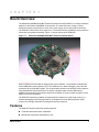
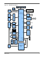
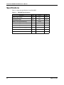
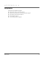
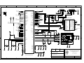
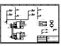
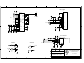
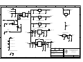
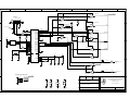
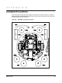
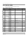
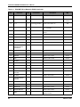
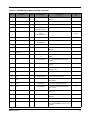
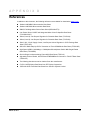
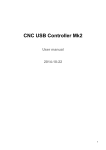
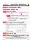
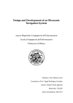
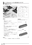
Stellaris® LM3S9B92 EVALBOT Robotic Evaluation Board User ’s Manual EK-EVAL BOT -U M-00 Copyrig ht © 201 1 Te xas In strumen ts Copyright Copyright © 2011 Texas Instruments, Inc. All rights reserved. Stellaris and StellarisWare are registered trademarks of Texas Instruments. ARM and Thumb are registered trademarks, and Cortex is a trademark of ARM Limited. Other names and brands may be claimed as the property of others. Texas Instruments 108 Wild Basin, Suite 350 Austin, TX 78746 http://www.ti.com/stellaris 2 March 19, 2011 Table of Contents Chapter 1: Board Overview.............................................................................................................................. 7 Features.............................................................................................................................................................. 7 Block Diagram .................................................................................................................................................... 8 Specifications.................................................................................................................................................... 10 Chapter 2: Hardware Description .................................................................................................................. 11 LM3S9B92 Microcontroller ............................................................................................................................... 11 Clocking ........................................................................................................................................................ 11 Reset............................................................................................................................................................. 11 Power Supplies ............................................................................................................................................. 11 Organic LED Display..................................................................................................................................... 12 microSD CARD ............................................................................................................................................. 12 Audio............................................................................................................................................................. 12 Ethernet ........................................................................................................................................................ 12 USB............................................................................................................................................................... 13 Robotic Features........................................................................................................................................... 13 Expansion ..................................................................................................................................................... 13 Debugging..................................................................................................................................................... 13 Appendix A: Schematics................................................................................................................................ 15 Appendix B: Component Locations.............................................................................................................. 21 Appendix C: Bill of Materials (BOM) ............................................................................................................. 23 Appendix D: References ................................................................................................................................ 27 March 19, 2011 3 List of Figures Figure 1-1. Stellaris® LM3S9B92 EVALBOT Robotic Evaluation Board ........................................................... 7 Figure 1-2. EVALBOT Block Diagram ............................................................................................................... 9 Figure B-1. EVALBOT Component Locations.................................................................................................. 21 March 19, 2011 4 List of Tables Table 1-1. Table 2-1. Table 2-2. Table C-1. EVALBOT Specifications............................................................................................................... 10 EVALBOT Power Supplies............................................................................................................ 12 Connector Part Numbers............................................................................................................... 13 EVALBOT Bill of Materials (BOM)................................................................................................. 23 March 19, 2011 5 Stellaris® LM3S9B92 EVALBOT User’s Manual 6 March 19, 2011 C H A P T E R 1 Board Overview The Stellaris® LM3S9B92 EVALBOT Robotic Evaluation Board (EVALBOT) is a robotic evaluation platform for the Stellaris LM3S9B92 microcontroller. The board also uses a range of Texas Instruments analog components for motor drive, power supply, and communications functions. The EVALBOT’s electronics arrive ready-to-run. The board's robotics capabilities require less than 30 minutes of mechanical assembly. Figure 1-1 shows a photo of the EVALBOT. Figure 1-1. Stellaris® LM3S9B92 EVALBOT Robotic Evaluation Board When roaming, three AA batteries supply power to the EVALBOT. The EVALBOT automatically selects USB power when tethered to a PC as a USB device or when debugging. Test points are provided to all key EVALBOT signals. Two 20-pin headers enable future wireless communications using standardized Texas Instruments’ low-power embedded radio modules (EM boards). Additional uncommitted microcontroller signals are available on break-out pads arranged in rows adjacent to the microcontroller. The EVALBOT has factory-installed quickstart software resident in on-chip Flash memory. For software debugging and Flash programming, an integrated In-Circuit Debug Interface (ICDI) requires only a single USB cable for debug and serial port functions. Features The EVALBOT board includes the following features: Evaluation board with robotic capabilities Mechanical components assembled by user March 19, 2011 7 Stellaris® LM3S9B92 EVALBOT User’s Manual Stellaris® LM3S9B92-IQC80 microcontroller MicroSD card connector I2S audio codec with speaker USB Host and Device connectors RJ45 Ethernet connector Bright 96 x 16 Blue OLED display On-board In-Circuit Debug Interface (ICDI) Battery power (3 AA batteries) or power through ICDI USB cable NOTE: EVALBOTs with serial numbers less than 50910-1500 do not support using the ICDI USB connector as a power source. During debugging, either install batteries or connect the USB device connector to a power source. Wireless communication expansion port Robot features – Two DC gear-motors provide drive and steering – Opto-sensors detect wheel rotation with 45° resolution – Sensors for “bump” detection Block Diagram The EVALBOT evaluation board uses the Stellaris® LM3S9B92 microcontroller and includes a 10/100 Ethernet port and a USB 2.0 full-speed On-the-Go (OTG) port. The EVALBOT combines all mechanical and electrical components on a single circuit board. Figure 1-2 on page 9 shows a block diagram of the electrical section of the EVALBOT. 8 March 19, 2011 Figure 1-2. EVALBOT Block Diagram I/ O Signal Break -out Status GPIO Boost Converter GPIO GPIO I2C GPIO +5.25V Tempest- class Microcontroller SPI USB Host USB Mux MicroSD card slot 1GB USB Ethernet USB Device LDO Regulator Power Mux 96x16 OLED Graphics display Boost Converter 200mA RJ45 Jack+ Magnetics Ethernet GPIO +3.3V GPIO Detector Switches Bump Sensors GPIO Speaker +12V I2S I2C I2 S CODEC w/ Amp 1.5V 1.5V Right- side Motor 1.5V Motor Driver DRV880x M PWM GPIO GPIO Push Switches Motor Driver DRV880x M Left- side Motor PWM GPIO JTAG/ SWD UART0 Debug Header InfraRed InfraRed Wheel Sensors USB Device DustDevil class 64-pin MCU USB for ICDI In- Circuit Debug Interface and Virtual COM Port March 19, 2011 9 Stellaris® LM3S9B92 EVALBOT User’s Manual Specifications Table 1-1 shows the specifications for the EVALBOT. Table 1-1. EVALBOT Specifications Parameter Min Typical Max Battery Supply Voltage 3.5 V 4.5 V 5.0 V USB Supply Voltage 4.0 V 5.0 V 5.25 V Battery current (typical stationary) – 100 mA – Battery current (typical in motion) – 200 mA – Power down supply current AA Alkaline Battery Capacity (typ) Reverse Battery Protection Allowable Battery/USB Current 0.5 uA – 2.5 A/Hra) – No 0.5A a. From Energizer E91 data sheet. 10 March 19, 2011 C H A P T E R 2 Hardware Description The EVALBOT consists of a 4-inch diameter circuit board populated with a Stellaris LM3S9B92 microcontroller and 14 additional Texas Instruments analog and digital semiconductors. LM3S9B92 Microcontroller The Stellaris LM3S9B92 is an ARM® Cortex™-M3-based microcontroller with 256-KB flash memory, 96-KB SRAM, 80-MHz operation, Ethernet MAC/PHY, USB Host/Device/OTG, and a wide range of other peripherals. See the LM3S9B92 microcontroller data sheet (order number DS-LM3S9B92) for complete device details. Unused microcontroller signals are routed to either the 20-pin EM expansion headers or to 0.1" pitch break-out pads which are labeled with their GPIO reference. An internal multiplexer allows different peripheral functions to be assigned to each of these GPIO pads. When adding external circuitry, consideration should be given to the additional load on the EVALBOT’s power rails. The reference design may include additional components necessary to address silicon errata. For details of those circuit functions, see the LM3S9B92 Errata document. Clocking The EVALBOT uses a 16.0-MHz crystal (Y3) to complete the LM3S9B92 microcontroller's main internal clock circuit. An internal PLL, configured in software, multiples this clock to higher frequencies for core and peripheral timing. A 25.0 MHz (Y1) crystal provides an accurate timebase for the Ethernet PHY. Reset The RESET signal into the LM3S9B92 microcontroller connects to the Reset/On switch (SW6) and to the ICDI circuit for a debugger-controlled reset. External reset is asserted (active low) under any one of three conditions: Power-on reset (filtered by an R-C network) Reset/On push switch SW6 held down By the ICDI circuit when instructed by the debugger (this capability is optional, and may not be supported by all debuggers). The OLED Module and Audio CODEC have special Reset timing requirements requiring a dedicated control line from the microcontroller. Power Supplies The EVALBOT can be powered either from batteries, the ICDI USB cable, or a USB device cable. The power source is determined by a Texas Instruments TPS2113 Auto Switching Power Mux and two Schottky diodes. Battery power is selected automatically when USB power is not present. March 19, 2011 11 Stellaris® LM3S9B92 EVALBOT User’s Manual Table 2-1 shows the EVALBOT’s power supplies. Each supply is generated directly or indirectly from the main power bus, +VS, using either a linear regulator or boost converter. Table 2-1. EVALBOT Power Supplies Name Voltage Max Current Use +VS 3.5 – 5.0 V 0.5 A Main power distribution bus to other power rails +3.3V +3.3 V 150 mA Logic power supply for main MCU, digital, and ICDI functions +3.3VA +3.3 V 150 mA Analog and I/O power for audio CODEC +1.8V +1.8 V 25 mA Digital/core power for audio CODEC +5V_HVBUS +5.25 V 100 mA USB Host power supply +12V +12 V 100 mA Motor driver power supply +10V +10 V 5 mA OLED bias power supply The board's on/off feature uses two push switches (SW5, SW6) and a simple feedback circuit through the inverter created by MOSFET Q3. An internal 1uA constant current source on the TPS2113's Enable pin (ENn) ensures that the TPS2113 is initially powered on when power is connected. Resistor R47 sets the overcurrent protection to 0.5 A. Organic LED Display The user interface consists of a 96 x 16 OLED display and two push switches. The OLED display has an integrated controller IC with a parallel, SPI, and I2C interfaces. In this design, the I2C interface is used. The OLED display is limited to 'write-only' in this mode, so pixel data cannot be read back from the display microSD CARD EVALBOT includes a microSD card interface, which interfaces to the MCU using a SPI interface. Because power to the SD card is not controlled removing or inserting the card while power is applied is not recommended. Audio A Texas Instruments TLV320AIC3107 CODEC adds a high performance audio stage to the EVALBOT. An integrated mono class-D amplifier drives an on-board speaker, with other audio inputs and outputs available on break-out header pads. An I2S interface carries the output (and input) audio data streams, while an I2C interface configures the CODEC. Most unused audio pins are available on nearby pads (0.05"pitch). Ethernet With its fully integrated 10/100 Ethernet MAC and PHY, the LM3S9B92 requires only a standard Jack with integrated magnetics and a few passive components. The TX and RX signals are routed to the jack as a differential pair. The PHY incorporates MDI/MDI-X cross-over, so the function of the TX and RX pairs can be swapped in software. 12 March 19, 2011 USB The LM3S9B92 microcontroller has Host, Device, and OTG USB capabilities. EVALBOT supports USB Host and Device with dedicated connectors and a Texas Instruments T3USB30E high-speed USB multiplexer to select between them. Robotic Features Two 12-V gear motors provide locomotion to the EVALBOT. A Texas Instruments’ DRV8801 Full-Bridge motor driver IC controls each motor; providing direction control, over-current and short-circuit protection, dead-time insertion and several switching schemes. Each EVALBOT wheel has two infra-red optical sensors which generate a quadrature signal as the wheel rotates. The IR emitters (D2, D3, D11, and D12) each connect to a GPIO signal so that the MCU can turn off the LEDs for power saving when not in motion. The GPIO outputs should be configured for 8 mA drive-strength to ensure the IR emitters have sufficient intensity. Left and right-side bumpers detect collisions using simple detector switches. The GPIO inputs should have internal pull-up resistors enabled and may optionally be configured to generate an interrupt when a collision occurs. Expansion The EM port on EVALBOT enables RF connectivity using a range of Low-Power RF Evaluation Modules (EM boards) from Texas Instruments. EM boards cover both Sub 1-GHz and 2.4GHz bands and are a supported by a several different protocol stacks. The EM port can also be used for general purpose expansion. SPI, UART, and GPIO signals are available. Table 2-2 lists the connector part numbers. Two identical connectors should be installed on a 1.20" pitch. Table 2-2. Connector Part Numbers Supplier Part Number Description Use Samtec TFM-110-02-S-D SMT Header 20-pos 0.050” pitch EVALBOT EM port Samtec SFM-110-02-S-D SMT Socket 20-pos 0.050” pitch EM board In additional to the EM port, EVALBOT also has 9 GPIO (PJ0..7, PE7), Power and GND connections on a 0.1" grid. Debugging EVALBOT includes an integrated In-Circuit Debug Interface (ICDI) for debugging, serial communication and power over a single USB cable. Based on an FTDI FT2232 USB controller, the ICDI supports all major Cortex-M3 development environments. Stellaris microcontrollers support programming and debugging using either JTAG or SWD. JTAG uses the signals TCK, TMS, TDI, and TDO. SWD requires fewer signals (SWCLK, SWDIO, and, optionally, SWO for trace). The debugger determines which debug protocol is used. An external debug interface can be used with EVALBOT if connector J4 is installed by the user. JTAG/SWD The FT2232 is factory-configured by Texas Instruments to implement a JTAG/SWD port (synchronous serial) on channel A and a Virtual COM Port (VCP) on channel B. This feature March 19, 2011 13 Stellaris® LM3S9B92 EVALBOT User’s Manual allows two simultaneous communications links between the host computer and the target device using a single USB cable. Separate Windows drivers for each function are provided on the Documentation and Software CD. The In-Circuit Debug Interface USB capabilities are completely independent from the LM3S9B92's on-chip USB functionality. A small serial EEPROM holds the FT2232 configuration data. The EEPROM is not accessible by the LM3S9B92 microcontroller. For full details on FT2232 operation, go to www.ftdichip.com. The FT2232 USB device performs JTAG/SWD serial operations under the control of the debugger. A simple logic circuit multiplexes SWD and JTAG functions and, when working in SWD mode, provides direction control for the bidirectional data line. Virtual COM Port The Virtual COM Port (VCP) allows Windows applications (such as HyperTerminal) to communicate with UART0 on the LM3S9B92 over USB. Once the FT2232 VCP driver is installed, Windows assigns a COM port number to the VCP channel. Serial Wire Out EVALBOT also supports the Cortex-M3 Serial-Wire Output (SWO) trace capabilities. Under debugger control, on-board logic can route the SWO data stream to the VCP transmit channel. The debugger software can then decode and interpret the trace information received from the Virtual Com Port. The normal VCP connection to UART0 is interrupted when using SWO. Not all debuggers support SWO. See the Stellaris LM3S9B92 Microcontroller Data Sheet for additional information on the Trace Port Interface Unit (TPIU). 14 March 19, 2011 A P P E N D I X A Schematics Schematics for the EVALBOT board follow. Microcontroller, Ethernet, and USB on page 16 Wheel Encoders, Motor Drivers, and Bumper Switches on page 17 User Interface, Audio, SD Card on page 18 Power Supplies on page 19 In-Circuit Debug Interface on page 20 March 19, 2011 15 Microcontroller, Ethernet, and USB USB HOST J7 USB DEVICE CON-USB-A-SMT SDCLK SDCS SDMISO SDMOSI ARST SDCARD +3.3V +3.3V R45 10K BUMP_R BUMP_L R_QEI_A L_QEI_A ENC_LED_PWR 80 79 78 77 PB2/I2C0SCL PB3/I2C0SDA PB6/I2S0TXSCK PE4/I2S0TXWS PE5/I2S0TXSD PF1/I2S0TXMCLK PD4/I2SRXSD PC0/TCK/SWCLK PC1/TMS/SWDIO PC2/TDI PC3/TDO/SWO 74 75 95 96 2 1 PE0/EPI0S8 PE1/EPI0S9 PE2/PHA0 PE3PHA1 PE6 PE7 47 42 41 PF0 PF4 PF5 PWM_R PHASE_R SLOW_DECAY VMON EN_12V USER_SW1 USER_SW2 PC4 PC5 PC6 PC7/PHB0 25 24 23 22 RF_UART_CTS RF_RST_SD RF_UART_RTS R_QEI_B PH0/PWM2 PH1/PWM3 PH2 PH3 PH4/SSI1CLK PH5 PH6/SSI1RX PH7/SSI1TX 86 85 84 83 76 63 62 15 PWM_L PHASE_L +5V_HVBUS U11 MFAULT RF_GPIO0 RF_GPIO1 RF_SPI_CLK RF_SPI_CS RF_SPI_MISO RF_SPI_MOSI DEVICE/HOST +3.3V C52 0.1UF S OE 10 C53 0.1UF 5 7 3 D2D2+ R49 10K 8 2 D1D1+ TP21 VCC PG0/I2C1SCL PG1/I2C1SDA PG7/PHB1 14 87 39 50 52 53 54 55 PJ0 PJ1 PJ2 PJ3 PJ4 PJ5 PJ6 PJ7 64 RESETN 17 16 48 49 USB0RBIAS 73 PF2/LED1 PF3/LED0 60 59 TS3USB30EDGS RF_UART_CTS ASDA ASCL 58 TXOP 43 R41 330 R40 C42 10PF R35 49.9 J1 R30 330 C45 12 11 Y3 16MHz +3.3V R29 12.4K C29 10PF C28 10PF C47 10PF C51 51 NC 3 VDDA 4 GNDA 9 21 45 57 69 82 94 GND1 GND2 GND3 GND4 GND5 GND6 GND7 C26 0.1UF 10PF 3 R5 10 46 4 RXIP 40 7 10PF G- +3.3V 1CT:1 TX+ RXIN 37 TXRX+ R33 49.9 R64 C40 10PF R31 49.9 RX- C65 0.1UF 3 C30 0.1UF C36 0.1UF 7 VDDC 38 88 6 8 C38 10PF 2 1 Y- 9 10 NC Y+ GND MH C44 0.01UF DESIGNER REVISION DATE JAG A 10/25/2010 TEXAS INSTRUMENTS STELLARIS PROJECT R MICROCONTROLLERS 108 WILD BASIN ROAD, SUITE 350 STELLARIS EVALBOT AUSTIN TX, 78746 =Ordering STELLARIS MICROCONTROLLER C27 1UF C49 0.1UF C41 0.01UF C46 0.1UF 7 6 SHIELD C48 0.01UF C37 0.1UF 8 10 +3.3V VDDC1 VDDC2 2 5 1CT:1 +3.3V LDO 1 4 8 20 32 44 56 68 81 93 RF_UART_RTS EM_CONNECTOR_2 10/100 BASET ETHERNET 5 TXON VDD1 VDD2 VDD3 VDD4 VDD5 VDD6 VDD7 VDD8 RF_RST_SD G+ 13 14 Y1 25MHz +3.3V +3.3V R32 49.9 +3.3V ERBIAS 1 3 5 7 9 11 13 15 17 19 2 4 6 8 10 12 14 16 18 20 VDD2(1.8V)OPTION VDD2(1.8V)OPTION VDD2(1.8V)OPTION VDD1(3.3V) VDD1(3.3V) BT/FM_AUD_I2S_FS RF_GPIO2 RF_CC_RSTN BT/FM_AUD_I2S_CLK RF_WCS_NSHUTD VSS ANA_AUDIO_FM_LEFT ANA_AUDIO_FM_RIGHT BT/FM_AUD_I2S_DX BT/FM_AUD_I2S_RX USBM USBP NC RF_UART_RTS RF_GPIO3 +3.3V OSC0 OSC1 33 J33 VSS RF_UART_CTS RF_SLOW_CLK(32K) RF_UART_RX RF_UART_TX RF_I2C_SDA RF_I2C_SCL RF_SDIO_CLK RF_SDIO_CMD VSS RF_SDIO_D0 RF_SDIO_D1 RF_SDIO_D2 RF_SDIO_D3 RF_GPIO0-GDO0 RF_GPIO1-GDO2 RF_SPI_CSn RF_SPI_CLK RF_SPI_MOSI RF_SPI_MISO EM_CONNECTOR_1 10K XTALNPHY XTALPPHY 1 3 5 7 9 11 13 15 17 19 2 4 6 8 10 12 14 16 18 20 R39 9.10K MDIO WIRELESS EM SOCKET J5 GND +3.3V H3-1 H4-1 H5-1 H6-1 H7-1 H8-1 H9-1 H10-1 R36 10K 1 9 DD+ +3.3V +3.3V 6 4 TP22 RF_SPI_CS RF_SPI_CLK RF_SPI_MOSI RF_SPI_MISO +3.3V 19 18 36 OLED_SCL OLED_SDA L_QEI_B 70 71 +DVBUS C59 0.1UF TP18 RF_SPI USB0DM USB0DP 7 +DVBUS H2-1 OLED_RST LED1 LED2 G 5 10 11 12 13 98 99 100 TP26 EN_VBUS ID 4 PD0/PWM0 PD1/PWM1 PD2 PD3/AIN12 PD5 PD6 PD7/CCP1 49.9 3 66 92 91 89 2 PB0 PB4/U1RX PB5/U1TX PB7 D+ G 4 67 34 D+ 3 PA2/SSI0CLK PA3/SSI0FSS PA4/SSI0RX PA5/SSI0TX PA7 PB1/USB0VBUS PA6 D2 28 29 30 31 35 72 65 90 6 5 61 97 TCK/SWCLK TMS/SWDIO TDI TDO/SWO TARGETRST DEBUG AUDIO TCK/SWCLK TMS/SWDIO R44 10K ASCL ASDA BCLK WCLK DOUT MCLK DIN PA0/U0RX PA1/U0TX V D- 15 16 H11-1 H12-1 H13-1 H1-1 26 27 +5V_HVBUS R43 CON-USB-MINI-B 5V 6 6 1 TARGET_RXD TARGET_TXD +3.3V 5 1 U1 J6 DESCRIPTION www.ti.com/stellaris MCU, Ethernet, USB FILENAME EvalBot Rev A.sch PART NO. EK-EVALBOT-A SHEET 1 OF 5 Wheel Encoders, Motor Drivers, and Bumper Switches RIGHT-WHEEL ENCODER LEFT-WHEEL ENCODER +3.3V +3.3V R57 2.7K R1 2.7K TP33 D11 TP1 +3.3V D2 R_QEI_A R54 R3 1 Q4 120 APECVA3010F3C +3.3V Q1 120 APA3010P3BT APECVA3010F3C 2 Infrared Infrared L_QEI_A 1 APA3010P3BT 2 Infrared Infrared +3.3V +3.3V D12 +3.3V D3 R55 R58 2.7K 120 +3.3V R4 R2 2.7K 120 TP34 APECVA3010F3C TP2 APECVA3010F3C R_QEI_B Infrared Infrared 1 Q5 L_QEI_B 1 Q2 APA3010P3BT 2 Infrared APA3010P3BT 2 Infrared MOTOR TERMINALS +12V A1 MOTOR-EVALBOT Q6 BSS123LT1 MOTOR_R- VCP 11 TP28 16 5 SLOW_DECAY TP25 1 PHASE_R TP24 4 3 +3.3V PWM_R TP27 15 14 MFAULT TP3 8 C58 PHASE ENABLE SLEEP FAULT VPROPI J8-1 C60 MH1 10PF J8-2 MOTOR_R+ OUT+ 6 MOTOR_R+ MOTOR_L- SENSE PAD GND1 GND2 10PF MOTOR_R- R52 7 A2 MOTOR-EVALBOT J13-1 C4 OUT- 9 J13-2 MOTOR_L+ DF13C-2P-1.25V 1.0 17 2 12 MH2 DF13C-2P-1.25V 0.1UF CP2 MODE1 MODE2 C55 1UF 13 2 VBB MH1 MH2 2 CP1 C57 0.1UF 1 10 ENC_LED_PWR 1 U13 BUMPER SWITCHES DRV8801RT Size 4 Mounting Hole SW3 TP19 A4 A3 A5 A6 BUMP_L ESE-22MH22 +12V SW4 TP20 BUMP_R U2 10 CP1 C5 0.1UF VCP 11 16 5 TP7 1 PHASE_L TP9 PWM_L 4 3 +3.3V 15 14 TP4 VBB 8 C6 0.1UF MODE1 MODE2 OUT+ PHASE OUT- FAULT VPROPI DRV8801RT ESE-22MH24 13 CP2 ENABLE SLEEP C1 1UF SENSE PAD GND1 GND2 6 MOTOR_L+ 9 7 17 2 12 MOTOR_L- R11 1.0 DESIGNER REVISION DATE JAG A 10/25/2010 TEXAS INSTRUMENTS STELLARIS PROJECT R MICROCONTROLLERS 108 WILD BASIN ROAD, SUITE 350 STELLARIS EVALBOT AUSTIN TX, 78746 DESCRIPTION www.ti.com/stellaris ?DESC1? ?DESC2? FILENAME PART NO. EvalBot Rev A.sch SHEET EK-EVALBOT-A 2 OF 5 User Interface, Audio, SD Card +3.3V +3.3V 96X16 OLED DISPLAY AUDIO CODEC AND AMPLIFIER U8 34 35 36 37 38 3 4 5 6 7 8 9 10 H20-1 H21-1 H22-1 H23-1 31 32 H24-1 +3.3VA C34 1UF +3.3VA C33 1UF U4 +3.3VA +3.3VA C16 0.1UF 40 18 13 25 12 21 SCL SDA MCLK BCLK WCLK DIN DOUT SPOP SPOM SWINP SWINM SWOUTP SWOUTM 26 23 + - 30 27 29 28 +3.3V H30-1 MICDET/LINE1LM HPCOM LINE1LP HPLOUT LINE1RP MIC3L/LINE1RM HPROUT LINE2LP LINE2RP/LINE2LM MIC3R/LINE2RM MICBIAS RESET GPIO1 IOVDD DRVDD2 DRVDD1 SPVDD AVDD_ADC AVDD_DAC LEFT_LOP RIGHT_LOP +3.3V AST-01508MR-R +3.3VA 15 14 17 R42 100K H26-1 H25-1 H27-1 +1.8V R37 1K TP15 19 20 TP16 OLED_SCL OLED_SDA H28-1 H29-1 TP17 +1.8V DVDD +10V 33 C23 0.1UF AVSS_DAC AVSS_ADC SPVSS DRVSS PAD C43 1UF R34 1K OLED_RST H31-1 H32-1 C31 0.1UF 22 11 24 16 41 DVSS C35 0.01UF R21 1.0M 39 TP10 TP11 microSD card connector SMT 1 2 3 4 5 6 7 8 SDCS SDMOSI SDCLK SDMISO SDCARD J2 R23 10K TP12 +3.3V +3.3V C21 0.1UF D8 NC1 CS DI VDD CLK VSS DO RSV X4 USER SWITCHES microSD CARD INTERFACE +3.3V R24 10K TP13 R50 C22 0.1UF NC1 VSS TEST5 TEST4 TEST3 TEST2 TEST1 NC2 NC3 NC4 VDD BS1 BS2 NC5 CS RES D/C WR RD D0/SCL D1/SDA D2 D3 D4 D5 D6 D7 IREF VCOMH VCC NC6 OLED-RIT-P13701 +3.3V STATUS LEDS 1 2 3 4 5 6 7 8 9 10 11 12 13 14 15 16 17 18 19 20 21 22 23 24 25 26 27 28 29 30 31 TLV320AIC3107 1 2 ASCL ASDA ARST MCLK BCLK WCLK DOUT DIN AUDIO K1 R17 1K R14 10K 9 X1 10 X2 11 X3 12 R16 1K SW1 LED1 330 USER_SW1 Green D5 R15 LED2 330 +3.3V Green R48 330 SW2 USER_SW2 D9 DESIGNER REVISION DATE JAG A 10/25/2010 TEXAS INSTRUMENTS STELLARIS PROJECT Green R MICROCONTROLLERS 108 WILD BASIN ROAD, SUITE 350 STELLARIS EVALBOT AUSTIN TX, 78746 DESCRIPTION www.ti.com/stellaris USER INTERFACE, AUDIO, SD CARD FILENAME PART NO. EvalBot Rev A.sch SHEET EK-EVALBOT-A 3 OF 5 Power Supplies +3.3V 150mA Logic Supply D7 +VS U10 +DVBUS TLV70033DDC 1 3 OMIT D6 +ICDI_VBUS C50 0.1UF +VS 0 OHMS 8 6 +VBAT C56 1UF 1 2 3 4 PWRENABLE IN1 IN2 STAT EN VSNS ILIM VDDC OMIT C54 1UF See LM3S9B92 Errata U16 OUT 7 +VS TLV70012DDC C63 10UF 16V 1 3 +3.3V 150mA CODEC Analog Supply IN EN GND TLV70033DDC 5 1 3 IN EN C19 0.1UF 5 4 OUT NC OUT NC 5 4 GND 2 U6 R47 330 TP23 VDDC +3.3V GND 2 TPS2113 TARGETRST R63 5 4 OUT NC U12 +VIN C61 0.1UF IN EN +3.3VA C25 1UF GND 2 When enabled, Power Mux Selects higher of IN1 or IN2. +1.8V 25mA CODEC Logic Supply On/Reset U5 DIO-BAS40-05 D10 SW6 1 3 3 C18 0.1UF Q3 BSS123LT1 5 4 OUT NC IN EN +VS 2 +VS TLV70018DDC 1 +1.8V R27 200K C24 1UF GND 2 R46 100K VMON R28 200K +5V 100mA USB Supply L2 Supply must be enabled for Host and Device modes. U14 TPS61073DDC VLF4012AT-4R7M1R1 Power Off 1 SW5 4.7uH 6 3 EN_VBUS VOUT TP32 5 VBAT +5V_HVBUS R56 1.30M EN FB 4 C64 10UF 16V GND 2 C62 1UF SW R51 100K +10V 5mA OLED Supply U7 R53 137K TPS71501DCK 4 +12V 3 TP29 IN OUT NC GND FB 2 C39 1UF R26 137K 1 2 3 EN_12V 1 D4 TPS61085 6 BAT-AA-KEYELCO-1028 R9 100K 2 +12V 100mA Motor Supply U9 BAT-AA-KEYELCO-1028 C11 1UF 7 4 IN SW EN FB FREQ GND COMP SS 2 +12V 1 R8 200K SS12 1 8 R13 22.6K C10 0.1UF BAT-AA-KEYELCO-1028 TP8 5 C7 10UF 16V R6 47K 2 BAT1 R25 1.0M VLF4012AT-4R7M1R1 4.7uH BAT2 +10V 1 L1 +VBAT BAT3 TP14 5 C2 1NF DESIGNER REVISION DATE JAG A 10/25/2010 TEXAS INSTRUMENTS STELLARIS PROJECT Chassis GND to Logic GND connection STELLARIS EVALBOT MICROCONTROLLERS AUSTIN TX, 78746 R38 0 OHMS R 108 WILD BASIN ROAD, SUITE 350 DESCRIPTION www.ti.com/stellaris Power Supplies FILENAME PART NO. EvalBot Rev A.sch SHEET EK-EVALBOT-A 4 OF 5 In-Circuit Debug Interface 74LVC125ARGY 13 12 G 7 U20-D DBG_AND_JTAG 6 U19-B R60 10K +3.3V 74LVC125ARGY 10 5 ID 4 D+ 3 D- 2 5V 1 6 5 CON-USB-MINI-B TCK/SWCLK 74LVC125ARGY 4 ICDI USB J3 DEBUG 11 74LVC125ARGY 1 2 R62 10K 9 8 TDI DBG_AND_SWD 3 +ICDI_VBUS U20-C U3 C3 0.1UF C8 6 R19 27 8 7 +VS +VS 3V3OUT 0.1UF USBDM USBDP R22 27 ACBUS0 ACBUS1 ACBUS2 ACBUS3 SI/WUA R59 1.5K R18 10K U15 VCC NC ORG GND CS SK DI DO 1 2 3 4 CAT93C46 48 1 2 47 R7 1.5K 43 44 Y2 6MHz EECS EESK EEDATA TEST XTIN XTOUT +VS 4 5 BDBUS0 BDBUS1 BDBUS2 BDBUS3 BDBUS4 BDBUS5 BDBUS6 BDBUS7 BCBUS0 BCBUS1 BCBUS2 BCBUS3 SI/WUB RESET RSTOUT PWREN GND GND GND GND VCC VCC VCCIOA VCCIOB 15 13 12 11 10 40 39 38 37 36 35 33 32 30 29 28 27 26 U19-A FT_TCK FT_TDI/DI FT_TDO/DO FT_TMS/OUTEN 1 U20-A FT_SRSTN DBGEN JTAG/SWD C20 27PF 9 18 25 34 45 AGND FT2232D AVCC 3 TMS/SWDIO 74LVC125ARGY U17-A 74LVC125ARGY 13 12 2 3 U17-B 11 1 +3.3V 5 R61 10K 6 U19-D 4 74LVC126A-QFN VCP_TXD VCP_TX_SWO TARGETRST SWO_EN 74LVC126A-QFN 10 8 9 TDO/SWO U17-C +3.3V 41 74LVC125ARGY +VS +3.3V C32 27PF 74LVC126A-QFN 2 3 42 14 31 4 6 5 U20-B R20 46 C9 0.1UF C17 0.1UF 330 C15 0.01UF C12 0.1UF C14 0.1UF TP6 R10 VCP_TXD 0 OHMS TARGET_RXD U17-D 11 12 74LVC126A-QFN 13 10 TP5 8 R12 VCP_RXD 9 TARGET_TXD 0 OHMS 74LVC125ARGY U19-C ICDI HEADER (NOT INSTALLED) DEBUG J4 +3.3V +3.3V +3.3V DESIGNER REVISION DATE JAG A 10/25/2010 TEXAS INSTRUMENTS +3.3V STELLARIS C13 0.1UF U19-E 14 PROJECT U20-E VDD GND VDD GND VDD GND 7 C42-10BSA1-G TMS/SWDIO TCK/SWCLK TDO/SWO TDI TARGETRST 14 2 4 6 8 10 7 1 3 5 7 9 14 +3.3V 7 8 7 6 5 ADBUS0 ADBUS1 ADBUS2 ADBUS3 ADBUS4 ADBUS5 ADBUS6 ADBUS7 24 23 22 21 20 19 17 16 U17-E R MICROCONTROLLERS 108 WILD BASIN ROAD, SUITE 350 STELLARIS EVALBOT AUSTIN TX, 78746 DESCRIPTION www.ti.com/stellaris In-Circuit Debug Interface 74LVC125ARGY 74LVC125ARGY 74LVC126A-QFN FILENAME PART NO. EvalBot Rev A.sch SHEET EK-EVALBOT-A 5 OF 5 A P P E N D I X B Component Locations Plots of the top-side and bottom-side component locations are shown in Figure B-1. Complete Gerber (RS274X) and PCB (Mentor PADS) files for the four-layer PCB layout are included in the EVALBOT Board Hardware Package. Figure B-1. EVALBOT Component Locations March 19, 2011 21 Stellaris® LM3S9B92 EVALBOT User’s Manual 22 March 19, 2011 A P P E N D I X C Bill of Materials (BOM) Table C-1 shows the Bill of Materials for the EVALBOT board design. Table C-1. EVALBOT Bill of Materials (BOM) Item Reference Qty Part Number Description Mfg Compact AA Battery holder, through-hole Keystone 1 BAT1-3 3 1028 2 C1 C11 C24-25 C27 C33-34 C39 C43 C54 C55 C56 C62 13 C2012X5R1E105K Capacitor, 1.0uF 25V 10% X5R 0805 TDK 3 C15 C35 C41 C44 C48 5 C0603C103J5RACTU Capacitor, 0.01uF 50V 5% 0603 X7R Kemet 4 C2 1 C0603C102J5RACTU Capacitor , 0.001uF 50V 5% 0603 X7R Kemet 5 C3 C5-6 C8-10 C12-14 C16-19 C21-23 C26 C30-31 C36-37 C46 C49-50 C52-53 C57-59 C61 C65 31 GRM188R71H104KA 93D Capacitor, 0.1uF 50V 10% 0603 X7R 6 C4 C28-29 C38 C40 C42 C45 C47 C51 C60 10 C0603C100J5GACTU Capacitor 10pF 50V 5% Ceramic NPO/COG 0603 Kemet 7 C20 C32 2 C0603C270J5GACTU Capacitor 27pF 50V 5% Ceramic NPO/COG 0603 Kemet 8 C7 C63-64 3 C3225X5R1C106M 9 D5 D8-9 3 LTST-C171GKT 10 D2-3 D11-12 4 APECVA3010F3C 11 D4 D6-7 4 SS12 12 D10 1 BAS40-05-7-F 13 J1 1 HR961160C J3011G21DNL J3011G21DNLT Connector, RJ45 with 10/100 magnetics, shielded SMT 14 J2 1 2908-05WB-MG Connector, Micro SD card, push-push SMT 15 J3 J6 2 54819-0572 16 J7 1 AU-Y1006-R 154-UAR42-E March 19, 2011 Capacitor, 10uF 16V 20% X5R 1210 LED, 0805 SMT Green LED, Infrared, Right Angle in 3.0 x 1.0mm SMT Diode, Schottky 20V 1A SMA Diode, Schottky 40V 100mA SOT23 Connector, USB Mini-B SMT 5pin Connector, USB Type A TDK TDK LiteOn Kingbright Taiwan Semi Diodes Hanrun Pulse 3M Molex Assmann Kobiconn 23 Stellaris® LM3S9B92 EVALBOT User’s Manual Table C-1. EVALBOT Bill of Materials (BOM) (Continued) Item 24 Reference Qty Part Number Description Mfg 17 J8 J13 2 DF13C-2P-1.25V(20) Connector, Header 2 pos, 1.25mm SMD Tin Hirose 18 K1 1 AST-01508MR-R Speaker, 8 ohm 0.3W 15mm PCB mount Projects Unlimited 19 L1-2 2 VLF4012AT-4R7M1R 1 20 Q1-2 Q4-5 4 APA3010P3BT 21 Q3 Q6 2 BSS123LT1 22 R11 R52 23 Inductor 3.7x3.5 SMT 1.1A Phototransistor, Infrared, Right Angle in 3.0 x 1.0mm SMT TDK Kingbright MOSFET, N-Channel 100V 170mA SOT-23 On Semi 2 Resistor 1 ohms 1% 0603 Generic R19, R22 2 Resistor 27 ohms 5% 0603 Generic 24 R1-2 R57-58 4 Resistor 4.7K 5% 0603 Generic 25 R13 1 Resistor 22.6K 1% 0603 Generic 26 R14 R18 R23-24 R36 R40 R44-45 R49 R60-62 12 Resistor 10K 5% 0606 Generic 27 R39 1 Resistor 9.10K 1% 0603 Generic 28 R21 R25 2 Resistor 1.0M 1% 0603 Generic 29 R26 R53 2 Resistor 137K 1% 0603 Generic 30 R29 1 Resistor 12.4K 1% 0603 Generic 31 R5, R64 2 Resistor, 10 ohms 5% 0603 Generic 32 R31-33 R35 R43 5 Resistor 49.9 ohms 1% 0603 Generic 33 R3-4 R54-55 4 Resistor 120 ohms 1% 0603 Generic 34 R10, R12, R38 3 Resistor 0 ohms 0603 Generic 35 R16-17 R34 R37 R47 R63 6 Resistor 1K 5% 0603 Generic 36 R7, R59 2 Resistor 1.5K 5% 0603 Generic 37 R15 R20 R30 R41 R48 R50 6 Resistor 330 ohms 5% 0603 Generic 38 R56 1 Resistor 1.30M 1% 0603 Generic 39 R6 1 Resistor 47K 5% 0603 Generic 40 R8 R27-28 3 Resistor 200K 1% 0603 Generic 41 R9 R42 R46 R51 4 Resistor 100K 1% 0603 Generic 42 SW3 1 ESE-22MH22 Switch, Detector-style Horizontal Right/top actuation Panasonic March 19, 2011 Table C-1. EVALBOT Bill of Materials (BOM) (Continued) Item Reference Qty Part Number Description Mfg 43 SW4 1 ESE-22MH24 Switch, Detector-style Horizontal - Left/top actuation Panasonic 44 SW1-2 SW5-6 2 EVQ-Q2B02W Switch, Tact 6mm SMT, 50gf Panasonic 45 U3 1 FT2232D 46 U15 1 CAT93C46YI-G / AT93C46A-10TU-2.7 IC, Serial Eeprom 1Kbit TSSOP8 47 Y1 1 NX5032GA-25.00000 0MHZ 8B48-25.000MHZ TR Crystal, 25.00MHz 5.0x3.2mm SMT 48 Y2 1 FOXSDLF/060-20 49 Y3 1 NX5032GA16.000000MHZ 50 J5 J33 2 TFM-110-02-S-D-K-A 51 U1 1 LM3S9B92-IQC80 52 U2 U13 2 DRV8801RTY 53 U4 1 TLV320AIC3107IRSB R 54 U5 1 55 U6 U10 56 IC, USB to Serial Interface TQFP48 Ftdi Catalyst Atmel NDK Suntsu Crystal, 6.00MHz HC49US SMT Fox Crystal, 16.00MHz 5.0x3.2mm SMT tbd Connector, 20 pos 1.27mm pitch, SMT Samtec IC, ARM Cortex-M3 Microcontroller TQFP100 TI IC, Full-Bridge Motor Driver TI IC, Audio CODEC with class D amplifier WQFN TI TLV70018DDCT IC, 1.8V 200mA Low-dropout voltage regulator TI 2 TLV70033DDCT IC, 3.3V 200mA Low-dropout voltage regulator TI U7 1 TPS71501DCKR IC, Adjustable 50mA Low-dropout voltage regulator, SC70 TI 57 U8 1 RGS08096016BW00 1 58 U9 1 TPS61085PWR 59 U11 1 TS3USB30EDGSR 60 U12 1 TPS2113PW 61 U14 1 TPS61073DDC 62 U17 1 63 U19 U20 64 65 OLED display, 96x16 Blue 13701 RiT IC, Step-up DC-DC Converter TI IC, High Speed USB 2.0 1:2 Mux/Demux Switch SSOP TI IC, 2-Ch Auto-switching power mux TI IC, Synchronous Boost Converter with 600-mA switch TI SN74LVC126ARGY IC, Quad tri-state line driver act lo TSSOP14 TI 2 SN74LVC125ARGY IC, Quad tri-state line driver act hi TSSOP14 TI PCB1 1 PCB-EVALBOT-A PCB, 4-layer 5.200x6.850" LABEL1 1 LABEL-EVALBOT Label, 2.90" x 0.50" 'Learn more at www.ti.com/EVALBOT'. Place on robot underside. March 19, 2011 25 Stellaris® LM3S9B92 EVALBOT User’s Manual 26 March 19, 2011 A P P E N D I X D References In addition to this document, the following references are available for download at www.ti.com. Stellaris LM3S9B92 Microcontroller Data Sheet Stellaris LM3S5632 Microcontroller Data Sheet DMOS Full-Bridge Motor Drivers Data Sheet (DRV8801RTY) Low-Power Stereo CODEC with Integrated Mono Class-D Amplifier Data Sheet (TLV320AIC3107) 200mA, Low IQ, Low Dropout Regulator for Portables Data Sheet (TLV70018) 200mA, Low IQ, Low Dropout Regulator for Portables Data Sheet (TLV70033) 50mA, 24V, 3.2-µA Supply Current, Low-Dropout Linear Regulator in SC70 Package Data Sheet (TPS71501) 650 kHz/1.2MHz Step-Up DC-DC Converter w/ Forced PWM Mode Data Sheet (TPS61085) High-Speed USB 2.0 (480 Mbps) 1:2 Multiplexer/Demultiplexer Switch With Single Enable Data Sheet (TS3USB30) Dual In/Single Out Autoswitching Power MUX Data Sheet (TPS2113) Adjustable, 600-mA Switch, 90% Efficient PFM/PWM Boost Converter in ThinSOT Data Sheet (TPS61073) The following data sheets can be obtained from the manufacturer: P13701 OLED Display Data Sheet from RiT Display Corporation SSD1300 OLED Controller Data Sheet from Solomon Systech Limited March 19, 2011 27 Stellaris® LM3S9B92 EVALBOT User’s Manual 28 March 19, 2011 IMPORTANT NOTICE Texas Instruments Incorporated and its subsidiaries (TI) reserve the right to make corrections, modifications, enhancements, improvements, and other changes to its products and services at any time and to discontinue any product or service without notice. Customers should obtain the latest relevant information before placing orders and should verify that such information is current and complete. All products are sold subject to TI’s terms and conditions of sale supplied at the time of order acknowledgment. TI warrants performance of its hardware products to the specifications applicable at the time of sale in accordance with TI’s standard warranty. Testing and other quality control techniques are used to the extent TI deems necessary to support this warranty. Except where mandated by government requirements, testing of all parameters of each product is not necessarily performed. TI assumes no liability for applications assistance or customer product design. Customers are responsible for their products and applications using TI components. To minimize the risks associated with customer products and applications, customers should provide adequate design and operating safeguards. TI does not warrant or represent that any license, either express or implied, is granted under any TI patent right, copyright, mask work right, or other TI intellectual property right relating to any combination, machine, or process in which TI products or services are used. Information published by TI regarding third-party products or services does not constitute a license from TI to use such products or services or a warranty or endorsement thereof. Use of such information may require a license from a third party under the patents or other intellectual property of the third party, or a license from TI under the patents or other intellectual property of TI. Reproduction of TI information in TI data books or data sheets is permissible only if reproduction is without alteration and is accompanied by all associated warranties, conditions, limitations, and notices. Reproduction of this information with alteration is an unfair and deceptive business practice. TI is not responsible or liable for such altered documentation. Information of third parties may be subject to additional restrictions. Resale of TI products or services with statements different from or beyond the parameters stated by TI for that product or service voids all express and any implied warranties for the associated TI product or service and is an unfair and deceptive business practice. TI is not responsible or liable for any such statements. TI products are not authorized for use in safety-critical applications (such as life support) where a failure of the TI product would reasonably be expected to cause severe personal injury or death, unless officers of the parties have executed an agreement specifically governing such use. Buyers represent that they have all necessary expertise in the safety and regulatory ramifications of their applications, and acknowledge and agree that they are solely responsible for all legal, regulatory and safety-related requirements concerning their products and any use of TI products in such safety-critical applications, notwithstanding any applications-related information or support that may be provided by TI. Further, Buyers must fully indemnify TI and its representatives against any damages arising out of the use of TI products in such safety-critical applications. TI products are neither designed nor intended for use in military/aerospace applications or environments unless the TI products are specifically designated by TI as military-grade or "enhanced plastic." Only products designated by TI as military-grade meet military specifications. Buyers acknowledge and agree that any such use of TI products which TI has not designated as military-grade is solely at the Buyer's risk, and that they are solely responsible for compliance with all legal and regulatory requirements in connection with such use. TI products are neither designed nor intended for use in automotive applications or environments unless the specific TI products are designated by TI as compliant with ISO/TS 16949 requirements. Buyers acknowledge and agree that, if they use any non-designated products in automotive applications, TI will not be responsible for any failure to meet such requirements. Following are URLs where you can obtain information on other Texas Instruments products and application solutions: Products Applications Audio www.ti.com/audio Communications and Telecom www.ti.com/communications Amplifiers amplifier.ti.com Computers and Peripherals www.ti.com/computers Data Converters dataconverter.ti.com Consumer Electronics www.ti.com/consumer-apps DLP® Products www.dlp.com Energy and Lighting www.ti.com/energy DSP dsp.ti.com Industrial www.ti.com/industrial Clocks and Timers www.ti.com/clocks Medical www.ti.com/medical Interface interface.ti.com Security www.ti.com/security Logic logic.ti.com Space, Avionics and Defense www.ti.com/space-avionics-defense Power Mgmt power.ti.com Transportation and Automotive www.ti.com/automotive Microcontrollers microcontroller.ti.com Video and Imaging www.ti.com/video RFID www.ti-rfid.com Wireless www.ti.com/wireless-apps RF/IF and ZigBee® Solutions www.ti.com/lprf TI E2E Community Home Page e2e.ti.com Mailing Address: Texas Instruments, Post Office Box 655303, Dallas, Texas 75265 Copyright © 2011, Texas Instruments Incorporated