1
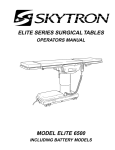
TECHNICAL SERVICES
ELITE SERIES SURGICAL TABLES
OPERATORS MANUAL
MODEL 6000/6001
INCLUDING BATTERY MODELS
17
MODEL ELITE 6001K
SKYTRON STANDARD LIMITED WARRANTY
SKYTRON, a Division of the KMW Group, Inc. (SKYTRON) warrants all new products sold by it directly or through a dealer or other
authorized representative, with exception to replacement parts, spares, bulbs (surgical lights), pads, and accessory items (surgical tables)
to be free from defects in material or workmanship, under normal use and service, for a period of two (2) years. This warranty shall include
the cost of repair or replacement of defective parts including the cost of service labor and travel time to the site of equipment use. Delays
caused by the user in accessing the equipment for repair will be chargeable at the normal hourly rate for service by SKYTRON’s authorized
service representative. The warranty period shall begin with the initial operation or one (1) year after receipt of the product, whichever shall
occur first.
Replacement parts, spares, bulbs (surgical lights), pads and accessory items (surgical tables) are warranted to be free from defects in material
or workmanship, under normal use and service, for a period of ninety (90) days from receipt by the ultimate user, with exception to replacement
parts supplied by SKYTRON, for products under warranty, which shall be covered for any remaining period of the original product warranty,
or for 90 days, whichever is of greater benefit to the ultimate user.
SKYTRON’s responsibility and liability shall be limited to the repair or replacement of any part which we, SKYTRON, determine to be defective
within the applicable warranty period. Minor adjustments required as a result of normal wear during the use of the product within the warranty
period are not covered under warranty. The labor portion of this warranty is covered by SKYTRON’s Authorized Service Agent. Repairs
made by others are not authorized nor covered by SKYTRON with respect to labor costs.
SKYTRON shall not be liable for any other expense, loss or damage, whether direct, incidental, consequential or exemplary arising in connection
with the sale or use of or the inability to use SKYTRON products.
NO EXPRESS WARRANTY IS GIVEN BY SKYTRON WITH RESPECT TO ITS PRODUCTS EXCEPT AS SPECIFICALLY SET FORTH
HEREIN. ANY WARRANTY IMPLIED BY LAW, INCLUDING ANY WARRANTY OF MERCHANTABILITY OR FITNESS FOR A PARTICULAR
PURPOSE, IS EXPRESSLY LIMITED TO THE TWO-YEAR AND 90-DAY TERMS SET FORTH ABOVE. THE FOREGOING STATEMENTS
OF WARRANTY ARE EXCLUSIVE AND IN LIEU OF ALL OTHER REMEDIES.
No dealer, agent, employee or other representative of SKYTRON is authorized to extend or enlarge this warranty.
REV. 3/97
Although current at the time of publication, SKYTRON’s policy of continuous development makes this
manual subject to change without notice.
13
TABLE OF CONTENTS
Title
Page
SPECIAL USER ATTENTION .................................................................................................................. 1
SECTION I INTRODUCTION ..................................................................................................................
1-1. General.........................................................................................................................................
1-2. Power Requirements ....................................................................................................................
1-3. Pendant Control Unit ....................................................................................................................
1-4. Floor Lock/Brake System .............................................................................................................
2
2
2
3
3
SECTION II BATTERY TABLE OPERATION .......................................................................................... 4
2-1. AC 120V Operation ...................................................................................................................... 4
2-2. Battery Operation ......................................................................................................................... 4
2-3. Automatic Shut-Off ....................................................................................................................... 5
2-4. Charging the Battery .................................................................................................................... 5
2-5. Emergency Back-Up Controls ...................................................................................................... 5
SECTION III OPERATION ....................................................................................................................... 6
3-1. Electrical Power ............................................................................................................................ 6
3-2. Positioning Functions ................................................................................................................... 6
a. Floor Lock/Brake system ........................................................................................................ 6
b. Emergency Brake Release ..................................................................................................... 6
c. Trendelenburg ........................................................................................................................ 7
d. Lateral Tilt ............................................................................................................................... 7
e. Back Section .......................................................................................................................... 7
f. Elevation ................................................................................................................................. 8
g. Leg Section ............................................................................................................................ 8
h. Flex Positioning ...................................................................................................................... 8
i. Return To Level ...................................................................................................................... 8
j. Pendant Control Storage ........................................................................................................ 9
3-3. Head Section ................................................................................................................................ 9
3-4. 180 Degree Table Top Rotation. .................................................................................................. 9
3-5. Leg Section (Elite 6000 only) ...................................................................................................... 10
3-6. Kidney Lift ................................................................................................................................... 10
3-7. Specialty Positioning .................................................................................................................. 11
SECTION IV MAINTENANCE................................................................................................................ 11
4-1. Preventive Maintenance ............................................................................................................. 11
4-2. Service ....................................................................................................................................... 11
15
SPECIAL USER ATTENTION
The extreme positioning capabilities of the 6000
Series Table requires special attention for possible
interference points when using multiple function
positioning. As with the operation of any surgical
table, a certain amount of care should be exercised
to position the patient safely. Although the thick
pads and sheets substantially protect the patient,
pinch points, located at the joints of the top section
should always be considered. BE SURE THAT
THE ARMS, HANDS AND FINGERS OF THE
PATIENT AND THOSE OF THE OPERATING
ROOM PERSONNEL ARE CLEAR OF ALL MOVING PARTS BEFORE MOVING THE TABLE.
Proper restraints should always be used for patient
safety.
IMPORTANT
The leg section may hit the table base or the floor
if both the leg and elevation systems are placed in
their full down position.
Certain accessories such as the Uro-Drain Tray,
Armboards and X-Ray top can be damaged when
changing the position of the table top sections.
Always look first to see if a desired movement is
going to interfere with any accessories in use.
WARNING
Always lock the table top in position after rotation.
DO NOT rotate the top with an unevenly distributed
patient weight load as instability may result.
The operator has the ultimate responsibility of
preventing damage to the table and surrounding
equipment or possible injury to the patient or staff.
In general, common sense will dictate when there
is a potential hazard.
WARNING
•Make sure the TOP ROTATION LOCK HANDLE
is tightened and the brakes are set before transferring the patient.
The following precautions should be reviewed
by all personnel prior to operating the table.
•Exercise caution with the table top rotated 90° to
the base since an improperly distributed patient
weight load may cause the table to be tipped over.
WARNING
DO NOT use the table in the presence of FLAMMABLE GASES (Flammable gases are not commonly used in the U.S.).
NOTE
In case of a power failure or an electrical problem
within the table, the emergency brake release
system can be used to move the table. The control
lever for this function is located on the side of the
table base and is identified by an EMERGENCY
BRAKE RELEASE label. Turn the lever counterclockwise to release the brakes.
IMPORTANT
•The Emergency Brake Release Valve must be
closed and tightened (clockwise) before any hydraulic function will operate.
•If the Emergency Brake Release Valve has been
operated, the UNLOCK button on the pendant
control will have to be pressed before brakes will
lock again.
WARNING
DO NOT unlock brakes when a patient is on the
table. An uneven patient weight load may cause
instability.
NOTE
If brakes fail to set, make sure the Emergency
Brake Release Lever is tight (clockwise).
NOTE
Normal table top position is with the head (and
back) section over the power cord end of the base.
NOTE
With an evenly distributed patient weight load, all
table positioning functions will operate smoothly
and quietly with a patient weight of up to 500
pounds.
CAUTION
To prevent damage to the kidney lift, make sure the
kidney lift is completely down before raising the
back section.
CAUTION
DO NOT sit on the end of the leg sections (6000
Series) as damage may result.
1
SECTION I INTRODUCTION
HEAD
SECTION
BACK
SECTION
OPT. KIDNEY
LIFT
LEG
SECTION
SEAT
SECTION
SPLIT LEG
SECTIONS
PENDANT
CONTROL
HEAD SECTION
RELEASE BAR
(NOT SHOWN)
SIDE
RAIL
TOP ROTATION
HANDLE
MODEL 6000(K)
SERVICE ACCESS
COVER
MAIN POWER
SWITCH
MODEL 6001(K)
Figure 1-1. Elite 6000/6001(K)
1-1. General
1-2. Power Requirements
SKYTRON’s Elite 6000 and 6001 Series Surgical
Tables are electro-hydraulically operated, general
purpose surgical tables. See figure 1-1.
The Elite 6000/6001 series Surgical Tables require a 120VAC, 60 Hz electrical power supply.
The table is equipped with a 15 foot long power
cord with a standard three prong, hospital grade
plug. The electrical protection fuses are located
behind a cover plate in the electrical enclosure on
the front edge of the base. See figure 1-2. The
main power ON/OFF switch is located on the
electrical enclosure.
The two models are identical except for the leg
sections. The 6000 series has manually positioned, independent, split-leg sections. The 6001
series has a single, electro-hydraulically operated
leg section.
A"K" after the model number designates a built-in
kidney bridge.
An "R" after the model number designates the
return to level feature.
The electro-hydraulic positioning functions operated by the hand-held, push button, pendant control unit are: trendelenburg, lateral tilt, back section,
elevation, leg section (6001 only), flex/reflex, return
to level, and the floor lock/brake system.
Manual controls are provided for head section
positioning, table top rotation, emergency brake
release, leg section (6000) and kidney lift.
2
ELECTRICAL
ENCLOSURE
POWER
CORD
MAIN POWER
SWITCH
COVER
PLATE
FUSE
Figure 1-2. Power Switch and Fuse Location
1-3. Pendant Control Unit
1-4. Floor Lock/Brake System
The hand-held pendant control unit (figure 1-3) has
a non-slip rubber cover which assures a positive
grip during use. A spring clip hanger located on the
back of the control allows it to be stored on the
trendelenburg cylinder cap bracket or the table
side rails.
The floor lock/brake system consists of four selfleveling, hydraulic brake cylinders which raise and
support the table base off from the casters. Press
the TABLE UP button on the pendant control to set
the table’s brakes. An electronic timer will activate
the brake system until the brakes are completely
set, approximately 8-10 seconds.
CLIP
ND
TRE
.
REV D
N
TRE
TILTT
H
RIG
TILTT
LEF
K
BAC N
W
DO
K
BAC
UP
LE
TABP
U
*
LEGN
W
DO
LEG
UP
LEX
REF
E
AK
BR OCK
L
UN
X
FLE
N
UR
RET
KES
RA
KB
TO
ESS
*
PR
FUNCTION
BUTTONS
LE
TABWN
DO
LOC
NOTE
Activating any function button will activate the brake system. Using the
TABLE UP function to set the brakes
provides a visual assurance that the
brakes are locked. As the brake cylinders are extending, the entire table will
move slightly. When the table top begins to elevate, the brakes are fully
locked.
ER
POW
ON
POWER
INDICATOR
Figure 1-3. Pendant Control Unit
The function push buttons are identified with abbreviated descriptions for all functions. See figure
1-4. The trendelenburg and table up buttons are
red, the remaining buttons are all black.
To unlock the brakes, press the BRAKE UNLOCK
button and release. The brakes will retract automatically in approximately 7-8 seconds.
WARNING
DO NOT unlock brakes when a patient
is on the table. An uneven patient
weight load may cause instability.
NOTE
In case of a power failure or an electrical problem within the table, the emergency brake release system can be
used to move the table. The control
lever for this function is located on the
side of the table base and is identified
by an EMERGENCY BRAKE RELEASE
label. Turn the lever counterclockwise
to release the brakes.
IMPORTANT
•The Emergency Brake Release Valve
must be closed and tightened (clockwise) before any hydraulic function will
operate.
•If the Emergency Brake Release Valve
has been operated, the BRAKE UNLOCK button on the pendant control
will have to be pressed before brakes
will lock again.
Figure 1-4. Function Push Buttons
3
SECTION II BATTERY TABLE OPERATION
2-1. AC 120V Operation
a. Be sure the power cord is plugged into a
properly grounded, Hospital Grade, 120VAC outlet. Make sure the power cord is routed to the outlet
to prevent it from being in the way of operating
personnel.
b. Depress the main power ON/OFF switch
located on the electrical enclosure. See figure 2-1.
The green AC 120V, Power-On indicator light
located in the lower right corner of the pendant
control will illuminate. See figure 2-2.
BATTERY CHARGING
INDICATOR LIGHT
NOTE
•If brakes fail to set, make sure the
Emergency Brake Release Lever is
tight (clockwise).
•If the Emergency Brake Release Valve
has been operated, the BRAKE UNLOCK button on the pendant control
will have to be pressed before brakes
will lock again.
NOTE
•Turning the Main Power Switch ON
will change the table operation to 120
VAC power regardless of the position of
the BATT button.
•If Battery operation is activated while
Main Power Switch is ON there will be
approximately a 4 second delay before
Battery operation activates.
2-2. Battery Operation
ELECTRICAL ENCLOSURE
MAIN POWER SWITCH
Figure 2-1. Main Power Switch
TRENDELENBURG
REVERSE
TRENDELENBURG
LATERAL
TILT LEFT
BACK UP
TABLE UP
LEG UP
FLEX
RETURN
(KR ONLY)
BATTERY ON/OFF
SELECTOR BUTTON
BATTERY POWER
INDICATOR LIGHT
(AMBER)
*
REV.
TREND
TREND
TILT
LEFT
TILT
RIGHT
BACK
UP
BACK
DOWN
TABLE
UP
TABLE
DOWN
LEG
UP
LEG
DOWN
FLEX
REFLEX
RETURN
BRAKE
UNLOCK
LATERAL
TILT RIGHT
BACK DOWN
TABLE DOWN
LEG DOWN
NOTE
The table will operate correctly on battery power with the power cord connected to a wall outlet or disconnected.
REFLEX
BRAKE
RELEASE
BATT
* PRESS TO LOCK BRAKES
BATTERY
POWER ON
AC120V POWER ON
INDICATOR LIGHT
(GREEN)
Figure 2-2. Pendant Control
c. The table is now ready for 120VAC operation.
Press the TABLE UP button on the pendant control
to set the table’s brakes. An electronic timer will
activate the brake system until the brakes are
completely set, approximately 8-10 seconds. Press
the desired function button to position the table.
4
a. Make sure the green, AC 120V, Power-On
indicator light, on the hand-held pendant control, is
OFF. See figure 2-2. If the indicator light is ON,
depress the main power ON/OFF switch, located
on the electrical enclosure to turn AC120V operation OFF.
b. Press the BATT button on the hand-held
pendant control. The amber BATTERY indicator
light, located in the lower left corner of the pendant
control, will illuminate. This confirms that the table
is now being operated with battery power.
c. The table is now ready to operate on battery
power. Press TABLE UP button on the pendant
control to set the table’s brakes. An electronic
timer will activate the brake system until the brakes
are completely set, approximately 8-10 seconds.
Press desired function button to position the table.
d. To extend the battery charge life, turn the
BATTERY power OFF with the pendant control
when the table is not going to be used.
NOTE
Battery Operation must be turned OFF
at the pendant control. It can not be
turned Off using the main power switch.
2-5. Emergency Back-up Controls
a. The emergency back-up control switches are
located under the access door on the service
access cover in the table base. See figure 2-3.
2-3. Automatic Shut-Off
a. To prevent unnecessary discharge of the
battery, a timer is built into the battery circuit. This
timer will automatically shut the battery power OFF
after 3-4 hours of table inactivity.
b. To turn the table “ON” again, simply press the
BATT button on the pendant control and the amber
indicator light will illuminate. Select any control
button to operate the table.
2-4. Charging the Battery
a. If the battery needs to be charged when
operating the table on battery power, the amber
indicator light on the pendant control will begin to
blink. At this time the battery needs to be recharged.
NOTE
When the amber light starts to blink
(indicating low power in battery) the
table will operate for approximately 5
continuous minutes, typically long
enough to use the table for the rest of
the day.
FUNCTION CONTROL
ACCESS DOOR
Figure 2-3. Emergency Controls Location
b. In the event of either a power failure or a
problem with the hand-held pendant control, the
table can be operated using the emergency backup switches. Simply push the desired emergency
switch in the appropriate direction to operate the
table functions. See figure 2-4. These switches are
spring-loaded so they return to the neutral or
center position when released.
LAT. TILT
LEFT/RIGHT
TABLE
UP/DOWN
b. To recharge the battery simply plug the
power cord into a 120VAC wall outlet, if not
already plugged in. Turn the main power ON/
OFF switch ON by depressing it. The green battery
charging light, located next to the power cord, will
illuminate.
c. A full battery charge will last approximately 2
weeks under normal operating conditions. However, it is recommended to charge the batteries at
the end of each week to establish a normal routine
protocol.
NOTE
The table can be operated on 120VAC
power while the battery is being recharged. The green AC 120V indicator
light (on the pendant control) will illuminate confirming 120VAC operation.
TREND
REV. TREND
BACK
UP/DOWN
LEG
UP/DOWN
Figure 2-4. Emergency Back-Up Controls
NOTE
The emergency back-up control
switches will function when the table is
operating on 120VAC power, battery
power, or turned off.
5
SECTION III OPERATION
3-1. Electrical Power
a. Floor Lock/Brake System. To activate the
a. Check to be sure the power cord is plugged
brakes without affecting table positioning, press
into a properly grounded, Hospital Grade, 120VAC
the TABLE UP button. See figure 3-3. The
outlet. Make sure the power cord is routed so as to
elevation cylinder will not function until the brakes
prevent it from being in the way of the operating
are completely extended.
personnel.
IMPORTANT
Prior to operating the table, observe all
table caution labels and review the SPECIAL USER ATTENTION section in the
front of this manual.
WARNING
Possible explosion hazard exists if table
is used in the presence of FLAMMABLE
ANESTHETICS.
Figure 3-3. Brake System Activation
b. Depress “Main Power ON/OFF” switch on
the electrical enclosure. See figure 3-1. The green
POWER ON indicator light on the pendant control
should now be illuminated.
Press the BRAKE UNLOCK button on the pendant
control to release the four self-leveling brake feet in
order to move the table. See figure 3-3. The brake
delay circuit automatically retracts the brake system with just one press of the BRAKE UNLOCK
button. It takes approximately 7-8 seconds to
totally release the system.
WARNING
DO NOT unlock brakes when a patient
is on the table. An uneven patient
weight load may cause instability.
Figure 3-1. Main Power Switch
3-2. Positioning Functions
The hand-held pendant control (figure 3-2) activates the following table functions:
6
Figure 3-2. Pendant Control Unit
b. Emergency Brake Release. In case of a
power failure or an electrical problem within the
table, the emergency brake release system can be
used to move the table. The control lever for this
function is located on the side of the table base and
is identified by an EMERGENCY BRAKE RELEASE label. Turn the lever counterclockwise to
release the brakes. See figure 3-4.
Figure 3-4. Emergency Brake Release
IMPORTANT
The Emergency Brake Release Valve
must be closed and tightened (clockwise) before any hydraulic function will
operate.
IMPORTANT
To maximize patient safety, utilize
proper restraint methods during extreme
lateral tilt positioning.
•If the Emergency Brake Release Valve
has been operated, the UNLOCK button on the pendant control will have to
be pressed before brakes will lock again.
NOTE
With an evenly distributed patient weight
load, all table positioning functions will
operate smoothly and quietly with a
patient weight of up to 500 pounds.
c. Trendelenburg. To place the surgical table
in a trendelenburg (head down) position, press the
TREND button (figure 3-5). Trendelenburg positioning of up to 30° may be obtained. To place the
table in a reverse trendelenburg (head up) position, press the REV TREND button. Reverse
Trendelenburg positioning of up to 30° may be
obtained.
IMPORTANT
To maximize patient safety, utilize
proper restraint methods during extreme trendelenburg positioning.
Figure 3-6. Lateral Tilt Positioning
CAUTION
To prevent damage to the kidney lift,
make sure the kidney lift is completely
down before raising the back section.
e. Back Section. To raise the back section,
press the BACK UP button (figure 3-7). The back
section will raise up to 90° above horizontal. To
lower the back section, press the BACK DOWN
button. The back section will go down to 40° below
horizontal.
Figure 3-5. Trendelenburg Positioning
d. Lateral Tilt. To achieve lateral tilt right (as
viewed from the head end of the table), press the
TILT RIGHT button (figure 3-6). Tilt of up to 30°
may be obtained. To achieve lateral tilt left, press
the TILT LEFT button. Tilt of up to 30° may be
obtained.
Figure 3-7. Back Section Positioning
7
f. Elevation. To raise table top, press the
TABLE UP button (figure 3-8). The table will lift a
patient weight of 500 pounds up to a maximum
height of 43". To lower the table top, press the
TABLE DOWN button. The table top will go down
to a minimum height of 28".
h. Flex Positioning. To place the table top in
a flex position from horizontal, press the FLEX
button (figure 3-10). To return the table top to a
horizontal position or into a reflex position, press
the RETURN or REFLEX button.
Figure 3-8. Elevation Function
g. Leg Section. To lower the leg section (6001
only), press the LEG DOWN button (figure 3-9).
The leg section will go down to 105° below horizontal. To raise the leg section, press the LEG UP
button. The leg section will go up to 20° above
horizontal.
Figure 3-10. Flex/Reflex Positioning
i. Return To Level (6001KR & 6001KRB only).
To return the table top to a level position, press the
RETURN button (figure 3-11).
NOTE
Elevation and brake system functions
are not affected by the return to level
function.
Figure 3-9. Leg Section Positioning (6001)
IMPORTANT
The Leg section may hit the table base
or the floor if both the leg and elevation
systems are placed in their full down
position.
8
Figure 3-11. Return To Level
j. Pendant Control Storage. When the Pendant Control is not in use, it should be stored on a
convenient side or end rail. A bracket is located
under the table top for storage of the Pendant
Control when the table is not in use and during
cleaning. See figure 3-12.
LEG
SECTION
HEAD
SECTION
LOCKING
KNOB
LOCKING
KNOB
Figure 3-14. Repositioning Head Section
3-4. 180 Degree Table Top Rotation.
Figure 3-12. Pendant Control Storage
Bracket
NOTE
Normal table top position is with the
head (and back) section over the power
cord end of the base.
3-3. Head Section
a. A quick release positioning bar located under
and to the front of the head section (figure 3-13) is
used to raise or lower the head section. Pull the
release bar toward the head end to allow the
section to pivot up or down. Positioning from 60°
above horizontal to 90° below horizontal in 15°
increments is available. Release the bar to lock the
head section in position.
a. The table top can be horizontally rotated 180°
without having to rotate the entire table. To rotate
the top, turn the TOP ROTATION LOCK HANDLE
counterclockwise (figure 3-15), grasp the table by
the head end and rotate the top 180° counterclockwise. Lock the top in position by tightening the TOP
ROTATION LOCK HANDLE clockwise.
WARNING
Always lock the table top in position
after rotation. DO NOT rotate the top
with an unevenly distributed patient
weight load as instability may result.
HEAD SECTION
RELEASE BAR
Figure 3-13. Head Section Adjustment
b. By loosening two locking knobs beneath the
back section, an additional 5" of longitudinal adjustment can be achieved. If desired, the head section
may be removed by loosening the locking knobs and
pulling it straight out of the back section. 6001 Series
Tables have the capability of attaching the head
section to the leg section for use as a foot extension
ONLY. Do Not reverse the patient on the table
without first consulting with SKYTRON. Two locking
knobs are located on the inside of the leg section for
securing the head section. See figure 3-14.
Figure 3-15. 180 Degree Top Rotation
9
b. The use of the optional support rod allows the
table top to be rotated 90° from the base. See
figure 3-16.
CAUTION
DO NOT sit on the end of the leg
sections as damage may result.
WARNING
•Make sure the TOP ROTATION LOCK
HANDLE is tightened and the brakes
are set before transferring the patient.
135˚
•Exercise caution with the table top
rotated 90° to the base since an improperly distributed patient load may
cause the table to be tipped over.
HORIZONTAL
LOCK HANDLE
Figure 3-18. Leg Horizontal Positioning
3-6. Kidney Lift
SUPPORT
ROD
The optional, built-in kidney lift is operated by a
manual hand crank system and allows 5 inches of
lift. See figure 3-19. The hand crank is stored in a
bracket on the lower right hand side frame (as
viewed from the head end of the table).
5" MAX
Figure 3-16. 90 Degree Top Rotation
3-5. Leg Section (Elite/6000 only)
The Elite/ 6000 series table has movable split-leg
sections. The individual sections can be rotated
both vertically and horizontally. To position a
section vertically, lift up slightly on the leg section side
rail and pull the LOCK TRIGGER outward. See
figure 3-17. The positioning range is from horizontal
to 105° below horizontal, in 15° increments.
VERTICAL
LOCK
TRIGGER
105˚
HAND CRANK
Figure 3-19. Optional Kidney Lift
To operate, connect the handle to the drive mechanism on either side of the back section. Rotate the
handle clockwise to raise the lift and counterclockwise to lower it.
CAUTION
To prevent damage to the kidney lift,
make sure the kidney lift is completely
down before raising the back section.
See figure 3-20.
Figure 3-17. Leg Vertical Positioning
To position the leg section horizontally, loosen the
LOCK HANDLE at least one full turn counterclockwise. See figure 3-18. Position the leg section as
desired and tighten the LOCK HANDLE. To remove the leg section, turn the LOCK HANDLE at
least five full turns counterclockwise and lift the leg
section up to remove it.
10
SEAT
SECTION
BACK
SECTION
Figure 3-20.
3-7. Specialty Positioning
The use of certain optional accessories available
from SKYTRON further extend the positioning
capabilities of the 6000/6001 Series Tables. Refer
to SKYTRON's "Positioning Guidelines" or contact
your SKYTRON representative for further details.
SECTION IV MAINTENANCE
4-1. Preventive Maintenance
4-2. Service
The following preventive maintenance checks and
services are recommended to ensure the serviceability and proper operation of your SKYTRON
Surgical Table.
Table maintenance can be performed by trained
maintenance personnel using SKYTRON authorized replacement parts and service techniques.
Service instructions and parts are available from
SKYTRON.
a. During normal cleaning, a general visual
examination should be made checking for leaks,
loose bolts or parts, and cracked, chipped, or
missing paint. Any necessary repairs should be
made.
b. Semi-annually the following checks and
services should be performed:
1. Check all hydraulic fittings, mini-valves and
slave cylinders for proper operation and
any signs of leaks.
2. Check the hydraulic speed controls and
adjust if necessary.
Preventive Maintenance contracts are available
through your local SKYTRON representative.
To obtain service instructions, replacement parts,
factory service or preventive maintenance contracts, contact your nearest SKYTRON representative or write or call:
SKYTRON
5000 36th Street S.E.
Grand Rapids, MI 49512
1-800-SKYTRON (1-800-759-8766)
Fax. 1-616-957-5053
3. Pressure check (with a gauge) the pressure relief valve.
4. Check all mechanical adjustments and adjust as necessary.
5. Check hydraulic fluid level.
6. Lubricate the slider assembly.
11
5000 36th Street S.E., Grand Rapids, MI 49512
1-800-SKYTRON or 1-616-957-0500 • FAX 1-616-957-5053
16