1
SilFlow ™ Deans’ Switch Kit
Installation Manual
1. Introduction
The SilFlow Deans’ Switch
is a new chromatography
solution
using
SGE’s
proprietary
SilFlow™
microchannel technology. SilFlow Deans’ Switch
SilFlow™ is an innovation in design and
fabrication resulting in a highly efficient and
reliable micro fluidic platform. The SilFlow™
Deans’ Switch is based on the famous
Dean’s principle, incorporating advanced
technical improvements. The Deans’ Switch
forms the core of most multidimensional
chromatography configurations.
SilFlow™ Deans’ Switch Kit is manufactured as
a capillary column gas flow switching system.
Applications are numerous such as heart
cutting, column back flushing, inlet switching,
column switching, detector switching, solvent
venting etc.
™
™
Features of SilFlow™ Deans’ Switch
• Chemically deactivated internal channels,
resulting in analysis with enhanced
quantitative accuracy and high reproducibility.
Can be incorporated into your system
without impacting your chromatography.
• Low dead volume connections, SilTite™
FingerTite metal ferrules result in a reliable
zero dead volume connection, giving you
optimized peak shapes.
• Superb operational stability. Thermal Lag –
tracks oven temperature up to 20 °C/min,
the design alleviates cold spots and sample
condensation. Maximum temperature – No
practical temperature limit. Limited only by
the temperature rating of the GC column
being used (420 °C).
• Easy to install and leak free. The kit
incorporates SilTite™ FingerTite fittings that
are easy to set up and can be tightened
using finger force to achieve a reliable seal,
even for the most sensitive MS systems – no
wrenches are required.
2. Contents of the SilFlow™
Deans’ Switch Kit
SilFlow™ Deans’ Switch Kit contains accessory
parts, tools and the installation manual.
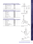
Parts and tools in the Kit are listed in Table 1
and shown in Figure 1.
Part
Number
Part Description
123726
SilFlow™, Deans’ Switch
-
Mounting Bracket
123751
2 m x 100 µm/363 µm VSD Tubing
123755
2 x 1.1 mm OD SS Tubing with 1/16” sleeve X 1 m
123706
SilFlow™ SilTite™ Ferrule 0.4 mm, Packet of 10
123707
SilFlow™ SilTite™ Ferrule 0.5 mm, Packet of 10
123705
SilFlow™ SilTite™ Ferrule 1.1 mm, Packet of 10
123704
SilTite™ FingerTite Nuts, Packet of 6
-
Screw for Mounting Bracket
123717
FingerTite Tool
-
Pre Swage Tool, 0.4 mm
-
Pre Swage Tool, 0.5 mm
-
Blanking Pins, Pack of 2
Table 1. Parts and Tools in the SilFlow™ Deans’ Switch Kit.
Figure 1. Kit contents – Parts and Tools identification.
3. Installing the SilFlow
Deans’ Switch Kit
™
In these instructions it has been assumed
the configuration is for heart cutting two
dimensional gas chromatography applications
(Figure 2). Please email [email protected] for
specific application requirements.
3.2Attaching the SilFlow™ Deans Switch
i.Mount the SilFlow™ Deans’ Switch to the
oven bracket with the guidance of the
locator pins ensuring it sits on the bracket
firmly (Figure 4).
Boss
aux gas (he)
Injector
Screw
Position 1
to detector
gc dean's Switch
P/N 123703
BPX50
gc column*
BPX5
gc column
P/N 054101
Location Pin
to detector
Figure 2. SilFlow™ Deans’ Switch set-up for heart cutting two dimensional gas
chromatography.
3.1 Installing the Mounting Bracket
Prior to installation ensure the GC oven is
turned off and cooled. Installing the mounting
bracket is straight forward. Make sure the
interior of the oven is free from obstacles such
as GC columns and column holders as this will
make the installation easier.
i.Identify a convenient location in the GC
oven. Consider the fact that after installation
it should be easy to access the components
of the system: columns, detectors, injectors
and accessories.
ii.Find an appropriate hole in the location of
the oven wall or carefully drill a 3.2 mm sized
hole in order to attach the screw.
iii.Secure the bracket against oven wall and
align the screw to the fitting and into the
wall (Figure 3).
Location Pin
Figure 3. Attaching the mounting bracket.
iv.T ighten the screw carefully with a
screwdriver.
Figure 4. Attaching the Deans’ switch.
Make sure the bosses face the correct direction
for easy access to install the tubing.
ii.Identify the appropriate port locations marked
on the back of the SilFlow™ Deans’ Switch
(Figure 5). Locate the appropriate SilFlow™
ferrules and nuts and prepare to connect the
relevant tubing to the SilFlow™ Deans’ Switch.
Figure 5. Identifying Deans switch port locations.
3.3 Installing the Columns
i. Re-install any column holders previously
removed from the oven in order to attach the
mounting bracket.
ii. Hook the GC columns (1st and 2nd Dimension)
onto the column holders firmly.
iii. Install one end of the 1st Dimension GC
column (Primary) to the injector in accordance
to the GC manufacturer’s recommendation.
iv. Connect the other end of the 1st Dimension GC
column to the ‘COL 1’ port of the Deans switch. v. Likewise install the 2nd Dimension GC column
between the ‘COL 2’ port of the SilFlow™
Deans’ Switch and the detector system
(2nd Dimension).
When connecting the capillary column to SilFlow™
Deans’ switch, use the Silflow™ FingerTite Jig to
pre-swage the ferrule (Figure 6) before attaching
the column to the SilFlow™ Deans’ Switch boss,
ensuring the capillary will not be crushed onto
the SilFlow™ Deans’ Switch channels.
There are two types of jigs available; one for the
0.4 mm ID ferrules (for 0.36 OD capillaries) and
one for the 0.5 mm ID ferrules (for 0.43 OD
capillaries).
Legend
1.
2.
3.
Jig body
Fixed pin to create ferrule offset
SilFlowTM FingerTite ferrule
4.
SilFlowTM Nut
Figure 6. Assembly with SilFlow ™ FingerTite Jig.
Use the FingerTite tool to tighten the FingerTite
nuts (Figure 7) applying finger force only.
Never use a wrench.
FingerTite Tool
Capillary Column
FingerTite Nut
Figure 7. Using the FingerTite Tool.
3.4 Installing the Restrictor Tubing
The dimensions of the restrictor tubing should
be carefully selected in such a way that the
gas flow resistance is similar to that of the
2nd Dimension GC column (Analytical). To keep
the time lag short as possible for the analytes to
reach the 1st Dimension detector (Monitoring)
the restrictor has to be short in length.
The balancing restrictor can be constructed
from the narrow bore uncoated deactivated
fused silica tubing (VSD tubing) supplied with
the kit. Use 0.1 mm ID tubing for the GC
system with 0.22 – 0.25 mm ID columns and
0.15, 0.22 or 0.25 mm ID tubing for the larger
diameter columns.
i.Calculate the dimension of the restrictor
tube based on the operating pressures
of the GC system and dimensions of the
2nd Dimension GC column. An example
is shown in Table 2, restrictor tube
has to be accurately trimmed until the
flow rate matches that through the
2nd Dimension GC column.
ii.Connect one end of the restrictor to the
‘DET’ port of the Deans’ switch. Use the
FingerTite Jig to pre-swage the ferrule.
iii.Install the other end of the restrictor
to the 1st Dimension detector system
(Monitoring) in accordance to the GC
manufacturer’s recommendation.
For operating pressures of the GC system,
refer to the recommendations of the column
manufacturer and consider method conditions.
As an example, method parameters for a heart
cutting two dimensional gas chromatography
technique using BPX5 and BPX70 columns for
the analysis of essential oil are listed in Table 2.
1st Dimension
30 m in length, 0.25 mm ID,
GC column
0.25 µm film; BPX5
2nd Dimension
30 m in length, 0.25 mm ID,
GC column
0.25 µm film; BPX70
Restrictor
0.1 mm ID VSD tubing 0.75 m in length
Carrier
Helium
Inlet Pressure
41.7 Psi
Mid point (Auxiliary) Pressure
27.5 Psi
Inlet Temperature
250 °C
Oven Temperature
140 °C
Detectors
FID at 300 °C
Table 2. Method parameters for a heart cutting two dimensional GC chromatography
– Analysis of essential oil.
3.5 Installing the Stainless Steel Tubing
for Auxiliary gas
i.Install 1.1 mm OD end of the 1/16 inch
sleeved stainless steel tube to the ‘SW 1’
port of the SilFlow™ Deans’ Switch. Use the
SilFlow™ Ferrule 1.1 mm and a FingerTite
nut for the connection.
ii. Likewise connect one end of the other 1/16
inch sleeved stainless steel tube to the ‘SW
2’ port of the SilFlow™ Deans’ Switch.
iii. Run the stainless steel tubes through the
oven ceiling and exit to the location where
the solenoid valve is installed. If your GC is
not equipped with EPC, SGE recommends
VSO-EP™ Electronic Pressure Control Unit.
See
www.parker.com/precisionfluidics.
Bend the tubes and align in such a way that
they run closely against the oven walls. This
provides easy access to the oven (Figure 8).
iv. Connect 1.1 mm OD end of the stainless
steel tubes to the two outputs of the
solenoid valve using the appropriate
connection. Refer to the manufacturer’s
user manual for correct installation.
4. Taking care of your Silflow™
Deans’ switch system
Tubing to the SilFlow™ Deans’ Switch can be
disconnected and reconnected many times
without removing the pre-swaged ferrules.
However, it is very important to inspect the
capillary end carefully before reconnecting to
the SilFlow™ Deans’ Switch. Make sure the end
is not squashed or cracked. If the capillary does
not have a clean square end, the column end
has to be cut again and a new ferrule to be
pre-swaged.
When the SilFlow™ Deans’ Switch is not
connected, protect it from particulates and
dust contaminating the internal channels.
Make sure to block the bosses using either
self-sealing nuts or pre-swaged ferrule to
pieces of metal wire and appropriate SilFlow™
FingerTite nuts.
1/16 inch sleeved stainless steel tube
Restrictor Tube
2nd Dimension column
SilFlow ™ Deans switch
1st Dimension column
Capillary Column
MN-0784-A © SGE Analytical Science Pty Ltd 08/2011
Figure 8. Hardware set-up for heart cutting two dimensional gas chromatography.
AUSTRALIA & PACIFIC REGION
SGE Analytical Science Pty Ltd
Toll Free:
1800 800 167
Tel: +61 (0) 3 9837 4200
Fax: +61 (0) 3 9874 5672
Email: [email protected]
CHINA
SGE Shanghai Representative Office
Tel: +86 21 6407 9382
Fax: +86 21 6407 9386
Email: [email protected]
MIDDLE EAST
SGE Gulf
Tel: +971 6 557 3341
Fax: +971 6 557 3541
Email: [email protected]
EUROPE
SGE Europe Ltd
European Head Office
Toll Free:
00800 2790 8999
Toll Free Fax:
00800 2626 2609
Tel:
+44 1908 568 844
Fax: +44 1908 566 790
Tel France:
+33 1 69 29 80 90
Fax France:+33 1 69 29 09 25
Tel Germany:
+49 (0) 6155 / 60746 0
Fax Germany: +49 (0) 6155 / 60746 50
Email: [email protected]
INDIA
SGE Laboratory Accessories Pvt Ltd
Tel: +91 22 24715896
Fax: +91 22 24716592
Email: [email protected]
UNITED STATES OF AMERICA
SGE Incorporated
Toll Free: (800) 945 6154
Tel: +1 512 837 7190
Fax: +1 512 836 9159
Email: [email protected]
JAPAN
SGE Japan Inc
Tel: +81 45 222 2885
Fax: +81 45 222 2887
Email: [email protected]