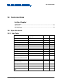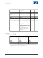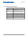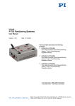
1
PZ255E S-334 Piezo Tip/Tilt Mirror User Manual Version: 1.0.1 Date: 19.09.2014 This document describes the following products: S-334.2SD1 High-Dynamics Piezo Tip / Tilt Platform, 50 mrad, SGS, Sub-D Connector, incl. Mirror S-334.2SL1 High-Dynamics Piezo Tip / Tilt Platform, 50 mrad, SGS, LEMO Connectors, incl. Mirror Physik Instrumente (PI) GmbH & Co. KG, Auf der Roemerstr. 1, 76228 Karlsruhe, Germany Phone: +49 721 4846-0, Fax: +49 721 4846-1019, E-mail: [email protected] Physik Instrumente (PI) GmbH & Co. KG is the owner of the following trademarks: PI®, PIC®, PICMA®, PILine®, PIFOC®, PiezoWalk®, NEXACT®, NEXLINE®, NanoCube®, NanoAutomation®, Picoactuator®, PInano® © 2014 Physik Instrumente (PI) GmbH & Co. KG, Karlsruhe, Germany. The text, photographs and drawings in this manual are protected by copyright. With regard thereto, Physik Instrumente (PI) GmbH & Co. KG retains all the rights. Use of said text, photographs and drawings is permitted only in part and only upon citation of the source. Original instructions First printing: 19.09.2014 Document number: PZ255E, KSch, Version 1.0.1 Subject to change without notice. This manual is superseded by any new release. The latest release is available for download (p. 3) on our website. Contents 1 About this Document 1.1 1.2 1.3 1.4 1.5 2 3 Goal and Target Audience of this User Manual ...................................................1 Symbols and Typographic Conventions ...............................................................1 Figures ..................................................................................................................2 Other Applicable Documents ................................................................................3 Downloading Manuals ..........................................................................................3 Safety 2.1 2.2 2.3 5 Intended Use ........................................................................................................5 General Safety Instructions ..................................................................................5 Organizational Measures ......................................................................................6 Product Description 3.1 3.2 3.3 3.4 3.5 3.6 3.7 3.8 1 7 Model Overview ....................................................................................................7 Product View.........................................................................................................8 Product Labeling .................................................................................................10 Scope of Delivery ...............................................................................................13 Accessories ........................................................................................................13 Suitable Electronics ............................................................................................14 Control ................................................................................................................15 Mirror ..................................................................................................................16 4 Unpacking 17 5 Installation 19 5.1 5.2 5.3 5.4 6 General Notes on Installation .............................................................................19 Mounting the S-334 and Connecting it to a Protective Earth Conductor ...........21 Removing the Transport Lock ............................................................................24 Connecting the S-334 to the Controller ..............................................................25 Start-Up and Operation 6.1 6.2 6.3 27 General Notes on Start-Up and Operation .........................................................27 Operating the S-334 ...........................................................................................30 Discharging the S-334 ........................................................................................30 7 Maintenance 7.1 7.2 7.3 33 General Notes on Maintenance ..........................................................................33 Cleaning the S-334 .............................................................................................34 Packing the S-334 for Transport.........................................................................34 8 Troubleshooting 37 9 Customer Service 39 10 Technical Data 41 10.1 10.2 10.3 Specifications......................................................................................................41 10.1.1 Data Table ........................................................................................41 10.1.2 Maximum Ratings .............................................................................42 10.1.3 Ambient Conditions and Classifications ...........................................43 Dimensions .........................................................................................................44 Pin Assignment ...................................................................................................45 10.3.1 S-334.2SD1: Sub-D 25 (m) Piezo and Sensor Connection .............45 10.3.2 S-334.2SL1: LEMO Piezo and Sensor Connections ........................46 11 Old Equipment Disposal 47 12 EC Declaration of Conformity 49 1 About this Document 1 About this Document In this Chapter Goal and Target Audience of this User Manual ............................................................ 1 Symbols and Typographic Conventions ........................................................................ 1 Figures ........................................................................................................................... 2 Other Applicable Documents ......................................................................................... 3 Downloading Manuals ................................................................................................... 3 1.1 Goal and Target Audience of this User Manual This user manual contains the information needed for the intended use of the S-334. Basic knowledge of servo systems, drive technologies and suitable safety measures is assumed. The latest versions of the user manuals are available for download (p. 3) on our website. 1.2 Symbols and Typographic Conventions The following symbols and typographic conventions are used in this user manual: CAUTION Dangerous situation If not avoided, the dangerous situation will result in minor injury. Actions to take to avoid the situation. NOTICE Dangerous situation If not avoided, the dangerous situation will result in damage to the equipment. Actions to take to avoid the situation. S-334 Piezo Tip/Tilt Mirror PZ255E Version: 1.0.1 1 1 About this Document INFORMATION Information for easier handling, tricks, tips, etc. Symbol/ Label Meaning 1. Action consisting of several steps whose sequential order must be observed 2. Action consisting of one or several steps whose sequential order is irrelevant List item p. 5 Cross-reference to page 5 RS-232 Labeling of an operating element on the product (example: socket of the RS-232 interface) Warning signs affixed to the product that refer to detailed information in this manual. 1.3 Figures For better understandability, the colors, proportions and degree of detail in illustrations can deviate from the actual circumstances. Photographic illustrations may also differ and must not be seen as guaranteed properties. 2 Version: 1.0.1 PZ255E S-334 Piezo Tip/Tilt Mirror 1 About this Document 1.4 Other Applicable Documents The devices and software tools which are mentioned in this documentation are described in their own manuals. Product Document E-616.SS0/E-616.S0 multi-channel servo controller for piezo tip/tilt mirrors / platforms with SGS PZ200E User Manual E-616.SS0G/E-616.S0G multi-channel servo controller for piezo tip/tilt mirrors / platforms with SGS, bench-top PZ219E User Manual E-509.S3 sensor/servo controller module PZ77E User Manual E500T0011 Technical Note for Analog Drivers E-503.00S piezo amplifier module PZ62E User Manual E-501.00 9.5’’ chassis for modular piezo controller system E-517.i3 interface / display module PZ214E User Manual 1.5 Downloading Manuals INFORMATION If a manual is missing or problems occur with downloading: Contact our customer service department (p. 39). INFORMATION For some products (e.g. Hexapod systems and electronics that are delivered with a CD), access to the manuals is password-protected. The password is stored on the CD. Availability of the manuals: Password-protected manuals: FTP download directory Follow the corresponding instructions for downloading. Freely available manuals: PI website S-334 Piezo Tip/Tilt Mirror PZ255E Version: 1.0.1 3 1 About this Document Download freely accessible manuals 1. Open the website http://www.pi-portal.ws. 2. Click Downloads. 3. Click the corresponding product category. 4. Go to the corresponding product code. The available manuals are displayed. 5. Click the desired manual and save it on the hard disk of your PC or on a data storage medium. Download password-protected manuals 1. Insert the product CD in the PC drive. 2. Switch to the Manuals directory on the CD. 3. In the Manuals directory, open the Release News (file including releasenews in the file name). 4. Find the user name and the password in the section "User login for software download" in the Release News. 5. Open the FTP download directory (ftp://pi-ftp.ws). − Windows operating systems: Open the FTP download directory in Windows Explorer. 6. Log in with the user name and the password from the Release News. 7. In the directory of the corresponding product, go to the Manuals sub-directory. 8. Copy the desired manual to the hard disk of your PC or to a data storage medium. 4 Version: 1.0.1 PZ255E S-334 Piezo Tip/Tilt Mirror 2 Safety 2 Safety In this Chapter Intended Use ................................................................................................................. 5 General Safety Instructions ........................................................................................... 5 Organizational Measures............................................................................................... 6 2.1 Intended Use The S-334 is a laboratory device as defined by DIN EN 61010-1. It is intended to be used in interior spaces and in an environment which is free of dirt, oil, and lubricants. In accordance with its design and realization, the S-334 is intended for the precise positioning and alignment of a mirror in two orthogonal axes with a common pivot point (parallel kinematics). The S-334 can be mounted in any orientation. The S-334 is equipped with strain gauge sensors (SGS). The intended use of the S-334 is only possible in combination with suitable electronics (p. 14) that is available from PI. The electronics is not included in the scope of delivery of the S-334. The electronics must provide the required operating voltages. To ensure proper performance of the servo-control system, the electronics must also be able to read out and process the signals from the strain gauge sensors. 2.2 General Safety Instructions The S-334 is built according to state-of-the-art technology and recognized safety standards. Improper use can result in personal injury and/or damage to the S-334. Only use the S-334 for its intended purpose, and only use it if it is in a good working order. Read the user manual. Immediately eliminate any faults and malfunctions that are likely to affect safety. The operator is responsible for the correct installation and operation of the S-334. S-334 Piezo Tip/Tilt Mirror PZ255E Version: 1.0.1 5 2 Safety 2.3 Organizational Measures User manual Always keep this user manual available by the S-334. The latest versions of the user manuals are available for download (p. 3) on our website. Add all information given by the manufacturer to the user manual, for example supplements or Technical Notes. If you pass the S-334 on to other users, also turn over this user manual as well as other relevant information provided by the manufacturer. Only use the device on the basis of the complete user manual. Missing information due to an incomplete user manual can result in minor injury and property damage. Only install and operate the S-334 after having read and understood this user manual. Personnel qualification The S-334 may only be installed, started up, operated, maintained and cleaned by authorized and appropriately qualified personnel. 6 Version: 1.0.1 PZ255E S-334 Piezo Tip/Tilt Mirror 3 Product Description 3 Product Description In this Chapter Model Overview ............................................................................................................. 7 Product View ................................................................................................................. 8 Product Labeling .......................................................................................................... 10 Scope of Delivery ........................................................................................................ 13 Accessories ................................................................................................................. 13 Suitable Electronics ..................................................................................................... 14 Control ......................................................................................................................... 15 Mirror ........................................................................................................................... 16 3.1 Model Overview Two standard versions of the S-334 tip/tilt mirror are available. Model Description S-334.2SD1 High-dynamics piezo tip / tilt platform, 50 mrad, SGS, Sub-D connector, incl. mirror S-334.2SL1 High-dynamics piezo tip / tilt platform, 50 mrad, SGS, LEMO connectors, incl. mirror For further technical data, see the specifications (p. 41). S-334 Piezo Tip/Tilt Mirror PZ255E Version: 1.0.1 7 3 Product Description 3.2 Product View Figure 1: Schematic product view of the S-334, without transport lock 1 Case (material: aluminum) 2 Mirror on moving platform 3 Cover plate 4 Base body (material: titanium) 5 Connection cable for piezo actuators and sensors Figure 2: Schematic diagram of the axes in relation to the cable exit 8 1 Axis 1 (corresponds to tip/tilt axis X on the E-616 controller) 2 Axis 2 (corresponds to tip/tilt axis Y on the E-616 controller) 3 Cable exit Version: 1.0.1 PZ255E S-334 Piezo Tip/Tilt Mirror 3 Product Description Figure 3: Maximum displacement in the positive direction of motion around axis 1. At the connected channel 1 of the amplifier, the output voltage UPiezo is 100 V. The displacement shown is strongly exaggerated for better understanding. Figure 4: Maximum displacement in the positive direction of motion around axis 2. At the connected channel 2 of the amplifier, the output voltage UPiezo is 100 V. The displacement shown is strongly exaggerated for better understanding. S-334 Piezo Tip/Tilt Mirror PZ255E Version: 1.0.1 9 3 Product Description 3.3 Product Labeling Figure 5: Position of the product labeling, for explanation of the labeling see table Figure 6: Product labeling on the bottom side of the S-334 10 Version: 1.0.1 PZ255E S-334 Piezo Tip/Tilt Mirror 3 Product Description The S-334 is labeled as follows: Labeling Description 1 S-334.2Sx1 Product name (example), the places after the point refer to the model 2 114010244 Serial number (example), individual for each S-334 Meaning of the places (counting from left): 1 = internal information, 2 and 3 = manufacturing year, 4 to 9 = consecutive numbers 3 Country of origin: Germany Warning sign "Observe manual!" 4 5 Country of origin WWW.PI.WS Manufacturer's address (website) 6 Symbol for the protective earth conductor, marks the position of the holes via which the S-334 is to be connected to the protective earth conductor 7 Manufacturer's logo 8 CE conformity mark 9 Old equipment disposal (p. 47) S-334 Piezo Tip/Tilt Mirror PZ255E Version: 1.0.1 11 3 Product Description S-334.2SD1: Labeling of the Sub-D 25 (m) connector Figure 7: Sub-D 25 (m) connector on the connection cable of the S-334.2SD1 1 Warning sign "Residual voltage": Notice of risk of electric shock (p. 5) S-334.2SL1: Labeling of the connection cables Figure 8: The cables of the S-334.2SL1 12 1 Sensor connection of axis 2, labeled AXIS 2 2 Sensor connection of axis 1, labeled AXIS 1 3 Piezo connection for 100 V fixed voltage, labeled PZT 100V 4 Piezo connection of axis 2, labeled PZT2 5 Piezo connection of axis 1, labeled PZT1 Version: 1.0.1 PZ255E S-334 Piezo Tip/Tilt Mirror 3 Product Description 3.4 Scope of Delivery Item ID Components S-334 Piezo tip/tilt mirror according to order PZ255E User manual (this document) in printed form S334T0001 Technical Note with handling information in printed form S334E0002 Transport lock 3.5 Accessories Order Number Description E-517.i3 Interface/display module, 24 bit D/A, TCP/IP, USB, RS-232, IEEE488, 3 channels Only S-334.2SL1: P-891.01 Extension cable for piezo voltage, LEMO connector(s), 1 m P-891.02 Extension cable for piezo voltage, LEMO connector(s), 2 m P-891.03 Extension cable for piezo voltage, LEMO connector(s), 3 m P-891.05 Extension cable for piezo voltage, LEMO connector(s), 5 m P-891.10 Extension cable for piezo voltage, LEMO connector(s), 10 m P-892.01 Extension cable, for strain gauge sensors, LEMO connector(s), 1 m P-892.02 Extension cable, for strain gauge sensors, LEMO connector(s), 2 m P-892.03 Extension cable, for strain gauge sensors, LEMO connector(s), 3 m P-892.05 Extension cable, for strain gauge sensors, LEMO connector(s), 5 m P-892.10 Extension cable, for strain gauge sensors, LEMO connector(s) 10 m To order, contact our customer service department (p. 39). S-334 Piezo Tip/Tilt Mirror PZ255E Version: 1.0.1 13 3 Product Description 3.6 Suitable Electronics Tip/Tilt Mirror S-334.2SD1 S-334.2SL1 Controller Amplifier Case Display E-616.SS0 multi-channel servo controller / driver for piezo tip/tilt mirror platforms with SGS and differential drive - - E-616.SS0G multi-channel servo controller / driver for piezo tip/tilt mirror platforms with SGS and differential drive, bench-top device 205 mm × 105 mm × 54.1 mm - E-509.S3 sensor / piezo servo-control module, SGS sensors, 3 channels E-501.00 9½''chassis for modular piezo controller system, 1 to 3 channels Optional: E-517.i3 interface/display module, 24 bit D/A, TCP/IP, USB, RS-232, IEEE488, 3 channels E-503.00S piezo amplifier module, -30 to 130 V, 2 channels, modified E-503.00 for S-330, S-334, S-340 tip/tilt systems, with one fixed voltage of +100V, two variable voltages To order, contact our customer service department (p. 39). 14 Version: 1.0.1 PZ255E S-334 Piezo Tip/Tilt Mirror 3 Product Description 3.7 Control Figure 9: Differential drive of the piezo tip/tilt mirror, functional principle using the tilting of a single axis as an example 1 Piezo actuator 1 of the axis 2 Piezo actuator 2 of the axis 3 Moving platform with mirror The S-334 is a piezo tip/tilt mirror with a differential piezo drive. Tip/tilt motions in two axes are realized by the pairwise interconnection of a total of four piezo actuators. Both pairs of actuators are electrically connected in such a way that when the piezo voltage UPiezo is changed, an increased voltage is applied to one actuator of a pair while the applied voltage on the other actuator is decreased by the same amount. The actuator with the increased voltage expands while the other actuator with the decreased voltage contracts. This produces the tip/tilt motion. For a simplified representation of the functional principle, only one axis is shown in the figure above. The moving platform is shown with a tilt of 0°. When the control input voltage UIn increases, piezo actuator 1 expands and piezo actuator 2 contracts. This produces a tilt in the positive direction. S-334 Piezo Tip/Tilt Mirror PZ255E Version: 1.0.1 15 3 Product Description Due to the type of interconnection, both actuators of a pair always move in opposite directions. It is thus impossible to command linear motions in the Z axis. The position of the Z axis can change with temperature fluctuations, however: Due to the symmetrical design of the piezo tip/tilt mirror, temperature fluctuations do not cause the moving platform to tilt but cause the length of the piezo actuators to change evenly in the direction of the Z axis. Most applications are not very sensitive to such deviations, as long as the tip/tilt angle does not change. The four piezo actuators of the S-334 are each equipped with a strain gauge sensor. For this reason, a servo loop with a sensor channel must be available to each pair of actuators, in addition to the amplifier channel. 3.8 Mirror The S-334 is equipped with a factory-mounted mirror with the following characteristics: 16 Diameter 10 mm 2 mm thickness Surface accuracy λ/10 Surface quality 20-10 Parallelism 30 arc seconds Version: 1.0.1 PZ255E S-334 Piezo Tip/Tilt Mirror 4 Unpacking 4 Unpacking INFORMATION The S-334 is delivered with a transport lock. To avoid scratches on the mirror surface during mounting, it is recommended not to remove the transport lock until after mounting (p. 24). 1. Unpack the S-334 with care. 2. Compare the contents against the items covered by the contract and against the packing list. 3. Inspect the contents for signs of damage. If there is any sign of damage or missing parts, contact PI immediately. 4. Keep all packaging materials in case the product needs to be returned. S-334 Piezo Tip/Tilt Mirror PZ255E Version: 1.0.1 17 5 Installation 5 Installation In this Chapter General Notes on Installation ...................................................................................... 19 Mounting the S-334 and Connecting it to a Protective Earth Conductor .................... 21 Removing the Transport Lock ..................................................................................... 24 Connecting the S-334 to the Controller ....................................................................... 25 5.1 General Notes on Installation CAUTION Dangerous voltage and residual charge on piezo actuators! The S-334 is driven by piezo actuators. Temperature changes and compressive stresses can induce charges in piezo actuators. After being disconnected from the electronics, piezo actuators can also stay charged for several hours. Touching or short-circuiting the contacts in the connector of the S-334 can lead to minor injuries. In addition, the piezo actuators can be destroyed by an abrupt contraction. Do not open the S-334. Discharge the piezo actuators of the tip/tilt mirror before installation: Connect the tip/tilt mirror to the switched-off PI controller, which is equipped with an internal discharge resistor. Do not pull out the connector from the electronics during operation. In the case of tip/tilt mirrors with Sub-D connectors: Touching the contacts in the connector can lead to an electric shock (max. 100 V DC) and minor injuries. Do not touch the contacts in the connector. Secure the connector of the tip/tilt mirror with screws against being pulled out of the controller. S-334 Piezo Tip/Tilt Mirror PZ255E Version: 1.0.1 19 5 Installation NOTICE Destruction of the piezo actuator by electric flashovers! The use of the S-334 in environments that increase the electrical conductivity can lead to the destruction of the piezo actuator by electric flashovers. Electric flashovers can be caused by moisture, high humidity, liquids and conductive materials such as metal dust. In addition, electric flashovers can also occur in certain air pressure ranges due to the increased conductivity of the air. Avoid operating the S-334 in environments that can increase the electric conductivity. Only operate the S-334 within the permissible ambient conditions and classifications (p. 43). NOTICE Destruction of the piezo actuator from short-circuiting without a discharge resistor! When a charged piezo actuator is short-circuited without a discharge resistor, this can lead to a contraction shock and thus to the destruction of the piezo ceramic. Only discharge the S-334 according to the instructions in "Discharging S-334" (p. 30). NOTICE Damage when the mirror is removed! The mirror of the S-334 may only be replaced by PI. Otherwise, the S-334 can be damaged. Do not remove the mirror of the S-334. If you need a different mirror, contact our customer service department (p. 39). NOTICE Warping of the S-334 due to mounting on uneven surfaces! Mounting the S-334 on an uneven surface can warp the S-334. Warping reduces the accuracy. 20 Mount the S-334 on an even surface. The recommended evenness of the surface is ≤30 µm. For applications with great temperature changes: Only mount the S-334 on surfaces that have the same or similar thermal expansion properties as the S-334. Version: 1.0.1 PZ255E S-334 Piezo Tip/Tilt Mirror 5 Installation NOTICE Damage from unsuitable cables! Unsuitable cables can damage the tip/tilt mirror and the electronics. Only use cables provided by PI for connecting the S-334 to the electronics. 5.2 Mounting the S-334 and Connecting it to a Protective Earth Conductor The S-334 can be mounted as follows: Mounting on a surface with two screws Clamping in a clamping holder Figure 10: M3 holes of the S-334.2Sx1 for mounting on a surface and/or protective earth connection Figure 11: Clamping width for mounting the S-334.2Sx1 by clamping S-334 Piezo Tip/Tilt Mirror PZ255E Version: 1.0.1 21 5 Installation NOTICE Damage due to incorrect mounting! Incorrect mounting can damage the S-334. When mounting the S-334 by clamping, observe the maximum clamping width of 20 mm and the maximum clamping force of 30 N. Only mount the S-334 according to the instructions in this manual. INFORMATION The contact of the S-334 with the protective earth conductor is made as follows: Two M3 holes in the base body of the S-334, marked with the symbol for the protective earth conductor Suitable conductive M3 screws When the S-334 is mounted on a surface via the two M3 holes: The surface is sufficiently conductive and connected to the protective earth conductor. When the S-334 is mounted by clamping: The protective earth conductor is connected to both M3 holes of the S-334 via two screws. INFORMATION Observe the applicable standards for mounting the protective earth conductor. Prerequisites You have read and understood the general notes on installation (p. 19). The S-334 is not connected to the controller. You have accounted for the space required for a cable routing free of kinks and in accordance with regulations. Tools and accessories For the dimensions of the tip/tilt mirror and the position and depth of the M3 holes, see "Dimensions" (p. 44). When the S-334 is mounted on a surface: You have provided a suitable surface: − 22 The surface must be connected to a protective earth conductor. Version: 1.0.1 PZ255E S-334 Piezo Tip/Tilt Mirror 5 Installation − Two through holes for M3 screws are present. − The holes for accommodating the screws have to be sufficiently conductive to ensure the proper functioning of the protective earth conductor. − The contact resistance at all connection points relevant for mounting the protective earth conductor is <0.1 Ω at 25 A. − The evenness of the surface is ≤30 µm. When the S-334 is mounted by clamping: − Suitable clamping holder for optical components, permissible clamping width of the S-334 see figure above Suitable protective earth conductor: Cross-sectional area of the cable 2 ≥0.75 mm Two electrically conductive M3 screws of appropriate length (p. 44) Suitable tools Mounting the S-334 on a surface and connecting it to a protective earth conductor 1. Align the S-334 on the surface so that the M3 holes in the S-334 and the surface overlap. 2. Introduce the two screws through the holes in the surface into the base body of the S-334 from below. 3. Tighten the two screws. − Maximum screw-in depth: 4 mm − Maximum torque: 1.1 Nm 4. Check that the S-334 fits without backlash. Mounting the S-334 with a clamping holder and connecting it to the protective earth conductor Mount the S-334 in the clamping holder. − Permissible clamping width, see figure above − Maximum clamping force: 30 N S-334 Piezo Tip/Tilt Mirror PZ255E Version: 1.0.1 23 5 Installation Connect the protective earth conductor to the M3 holes marked with the symbol for the protective earth conductor two screws. − Maximum screw-in depth: 4 mm − Maximum torque: 1.1 Nm in the base body of the S-334 via 5.3 Removing the Transport Lock The S-334 is delivered with a transport lock. Figure 12: Transport lock of the S-334, the arrows mark the recommended adhesion points Tools and accessories Suitable tool for removing the transport lock For removing the adhesion points, if necessary: isopropanol and cotton swab Prerequisite You have mounted the S-334 (p. 21). Removing the transport lock 1. Carefully remove the transport lock. 2. If necessary: Remove the adhesive strips for the transport lock and the adhesive residue with a cotton swab soaked in isopropanol. 3. Keep the transport lock in case the product needs to be transported again later. 24 Version: 1.0.1 PZ255E S-334 Piezo Tip/Tilt Mirror 5 Installation 5.4 Connecting the S-334 to the Controller Prerequisites You have read and understood the general notes on installation (p. 19). You have installed a suitable controller (p. 14). You have read and understood the user manual of the controller. The controller is switched off. Connecting the S-334.2SD1 to the E-616 controller 1. Connect the connector of the S-334.2SD1 with the corresponding socket of the controller (see user manual of the controller). 2. Secure the connection with the integrated screws against accidental disconnection. Connecting the S-334.2SL1 to E-50x modules 1. Connect the piezo connections of the S-334.2SL1 to the E-503.00S piezo amplifier module as follows: − PZT1 to PZT for channel 1 (CH1) − PZT2 to PZT for channel 2 (CH2) − PZT 100V to PZT for channel 3 (CH3) 2. Connect the sensor connections of the S-334.2SL1 to the E-509.S3 servo controller module as follows: − AXIS 1 to SENSOR for channel 1 (SERVO 1) − AXIS 2 to SENSOR for channel 2 (SERVO 2) S-334 Piezo Tip/Tilt Mirror PZ255E Version: 1.0.1 25 6 Start-Up and Operation 6 Start-Up and Operation In this Chapter General Notes on Start-Up and Operation .................................................................. 27 Operating the S-334 .................................................................................................... 30 Discharging the S-334 ................................................................................................. 30 6.1 General Notes on Start-Up and Operation CAUTION Risk of electric shock if the protective earth conductor is not connected! If a protective earth conductor is not or not properly connected, dangerous touch voltages can occur on the S-334 in the case of malfunction or failure of the system. If touch voltages exist, touching the S-334 can result in minor injuries from electric shock. Before start-up, establish contact between the S-334 and the protective earth conductor (p. 21). Do not remove the protective earth conductor during operation. Make sure that the contact resistance is <0.1 Ω at 25 A at all connection points relevant for mounting the protective earth conductor. If the protective earth conductor has to be temporarily removed (e.g. for modifications), reconnect the S-334 to the protective earth conductor before starting it up again. S-334 Piezo Tip/Tilt Mirror PZ255E Version: 1.0.1 27 6 Start-Up and Operation NOTICE Destruction of the piezo actuator by electric flashovers! The use of the S-334 in environments that increase the electrical conductivity can lead to the destruction of the piezo actuator by electric flashovers. Electric flashovers can be caused by moisture, high humidity, liquids and conductive materials such as metal dust. In addition, electric flashovers can also occur in certain air pressure ranges due to the increased conductivity of the air. Avoid operating the S-334 in environments that can increase the electric conductivity. Only operate the S-334 within the permissible ambient conditions and classifications (p. 43). NOTICE Reduced lifetime of the piezo actuator due to permanently high voltage! The permanent application of a high static voltage to piezo actuators leads to a considerable reduction in the lifetime of the piezo ceramic of the actuator. When the S-334 is not used but the controller remains switched on to ensure temperature stability, discharge the S-334 (p. 30). NOTICE Impermissible mechanical load due to unsuitable control! The S-334 is designed for the following control: Maximum range of piezo voltage: 0 to 100 V Minimum rise time of the piezo voltage: 10 ms Maximum frequency with sinusoidal control signal: 50 Hz Maximum frequency with 10 ms rise time of the piezo voltage: 30 Hz An unsuitable control of the S-334 results in an impermissibly high mechanical load and can cause damage to the S-334. 28 Set the control signal so that the piezo voltage stays within the limit values. Only use the S-334 in closed-loop operation. Version: 1.0.1 PZ255E S-334 Piezo Tip/Tilt Mirror 6 Start-Up and Operation NOTICE Damage from start-up with transport lock! If the transport lock has not been removed before start-up, the mirror can collide with the transport lock. Collisions can cause damage to the mirror. Remove the transport lock before you start up the S-334 (p. 24). INFORMATION Systems consisting of an S-334 and controller are calibrated at the factory to achieve optimum performance. Note the assignment of the axes to the controller channels, which is given by the calibration label of the piezo servo controller. Do not change the dynamic servo-control parameters of the controller (e.g. P term and I term) for a system calibrated by PI. Only when replacing system components: If the controller or the S-334 has to be replaced, recalibrate the axis displacement (see controller manual) or contact our customer service department (p. 39). If the controller has to be replaced, set the dynamic servo-control parameters (see controller manual). INFORMATION Sound and vibration (e.g. footfall, impacts) can be transmitted to the tip/tilt mirror and can affect its performance with regard to position stability. Avoid transmitting sound and vibration while the tip/tilt mirror is being operated. INFORMATION In the case of a S-334 tip/tilt mirror with Sub-D connector, ground loops can occur when the tip/tilt mirror is grounded via its protective earth connection as well as by the shield of the connection cable for the electronics. If a ground loop occurs, contact our customer service department (p. 39). INFORMATION The S-334.2SL1 can also be optionally operated from a PC via a program such as e.g. PIMikroMove using the digital E-517.i3 interface module. S-334 Piezo Tip/Tilt Mirror PZ255E Version: 1.0.1 29 6 Start-Up and Operation INFORMATION The expansion of the piezo actuators depends on the ambient temperature and can vary by up to 10 % in the given temperature ranges (p. 43). 6.2 Operating the S-334 Prerequisites You have read and understood the general notes on start-up and operation (p. 27). You have read and understood the user manual of the controller. If you use the E-517.i3 interface module: You have read and understood the user manual of the interface module and the PC software. You have properly installed the tip/tilt mirror (p. 19). The controller and the required PC software have been installed. All connections with the controller have been set up (see user manual of the controller). You have removed the transport lock (p. 24). You have ensured that the servo mode is switched on for all axes of the S-334 on the controller. Operating the S-334 Follow the instructions in the manual of the controller used for start-up and operation of the S-334. 6.3 Discharging the S-334 The S-334 must be discharged in the following cases: Before installation Before pulling out the connector (e.g. before cleaning and transport of the S-334 and for modifications in the application) If the S-334 is not used but the controller remains switched on to ensure temperature stability The S-334 is discharged through the internal discharge resistor of the controller from PI. 30 Version: 1.0.1 PZ255E S-334 Piezo Tip/Tilt Mirror 6 Start-Up and Operation Discharging a S-334 that is connected to the controller 1. Switch the controller off. 2. Wait at least 10 seconds before pulling out the connector. Discharging a S-334 that is not connected to the controller Connect the S-334 to the switched-off controller from PI. S-334 Piezo Tip/Tilt Mirror PZ255E Version: 1.0.1 31 7 Maintenance 7 Maintenance In this Chapter General Notes on Maintenance ................................................................................... 33 Cleaning the S-334 ...................................................................................................... 34 Packing the S-334 for Transport ................................................................................. 34 7.1 General Notes on Maintenance NOTICE Misalignment from loosening screws! The S-334 is maintenance-free and achieves its positioning accuracy as a result of the optimum alignment of mechanical components and piezo actuators. Loosened screws cause a loss in positioning accuracy. Only loosen screws according to the instructions in this manual. Do not open the S-334. NOTICE Damage when the mirror is removed! The mirror of the S-334 may only be replaced by PI. Otherwise, the S-334 can be damaged. Do not remove the mirror of the S-334. If you need a different mirror, contact our customer service department (p. 39). S-334 Piezo Tip/Tilt Mirror PZ255E Version: 1.0.1 33 7 Maintenance 7.2 Cleaning the S-334 NOTICE Damage due to incorrect cleaning! The mirror of the S-334 can be damaged from applying force during cleaning. Only clean the mirror when actually necessary. Avoid exerting any force on the mirror during cleaning. Do not use compressed air. Prerequisites You have discharged the piezo actuators of the S-334 (p. 30). You have disconnected the S-334 from the controller. Tools and accessories Bellows Optic brush Cleaning the S-334 Clean the surfaces and the mirror of the S-334 with bellows and/or an optic brush without exerting force. Do not use compressed air for cleaning. Do not do any ultrasonic cleaning. 7.3 Packing the S-334 for Transport Accessories 34 Easy to remove, double-sided adhesive tape Suitable foil Transport lock (p. 17) Version: 1.0.1 PZ255E S-334 Piezo Tip/Tilt Mirror 7 Maintenance Packing the S-334 for transport Figure 13: Transport lock of the S-334, the arrows mark the recommended adhesion points 1. Fix the transport lock on the S-334 with double-sided adhesive tape as shown in the figure above. Figure 14: S-334 in the original packaging, with dessicants 2. Pack the S-334 as shown in the figure above, if possible. S-334 Piezo Tip/Tilt Mirror PZ255E Version: 1.0.1 35 8 Troubleshooting 8 Troubleshooting Problem Possible Causes Solution No or uncontrolled motion Cable not connected correctly Check the cable connections (p. 25). Controller defective Contact our customer service department (p. 39). S-334 damaged due to openloop operation Contact our customer service department (p. 39). Reduced accuracy Cable defective Piezo ceramic defective after electric flashover Warped base body Only mount the S-334 on surfaces with the following characteristics: − − Impermissible clamping of the S-334 S-334 or controller has been replaced Evenness of at least 30 μm The thermal expansion properties are similar to those of the S-334 (e.g. surfaces made of titanium) Observe the permissible clamping width and clamping force (p. 21). After the S-334 or controller has been replaced, it is necessary to recalibrate the axis displacement. Perform a recalibration of the axis displacement (see controller manual) or contact our customer service department (p. 39). Axes were mixed up during connection Note the assignment of the axes to the controller channels, which is given by the calibration label of the piezo servo controller. Operating temperature outside of the permissible range (p. 41) Contact our customer service department (p. 39). Only with S-334.2SL1: If the problem that occurred with your system is not listed in the table above or cannot be solved as described, contact our customer service department (p. 39). S-334 Piezo Tip/Tilt Mirror PZ255E Version: 1.0.1 37 9 Customer Service 9 Customer Service For inquiries and orders, contact your PI sales engineer or send us an e-mail (mailto:[email protected]). If you have questions concerning your system, have the following information ready: Product codes and serial numbers of all products in the system Firmware version of the controller (if present) Version of the driver or the software (if present) Operating system on the PC (if present) The latest versions of the user manuals are available for download (p. 3) on our website. S-334 Piezo Tip/Tilt Mirror PZ255E Version: 1.0.1 39 10 Technical Data 10 Technical Data In this Chapter Specifications .............................................................................................................. 41 Dimensions .................................................................................................................. 44 Pin Assignment ............................................................................................................ 45 10.1 Specifications 10.1.1 Data Table S-334.2SL1 / S-334.2SD1 Active axes Unit Tolerance θX, θY Motion and positioning Integrated sensor SGS Closed-loop tilt angle 50 mrad Open-loop resolution 0.5 µrad typ. Closed-loop resolution 5 µrad typ. Linearity 0.05 % typ. Repeatability 5 µrad typ. Resonant frequency under load (with standard mirrors) 0.7 kHz ±20 % Load capacity 0.2 N max. Distance of pivot point to platform surface 4 mm ±0.1 mm µF ±20 % Mechanical properties Drive properties Ceramic type PICMA® P-885 Electrical capacitance per axis 3 S-334 Piezo Tip/Tilt Mirror PZ255E Version: 1.0.1 41 10 Technical Data S-334.2SL1 / S-334.2SD1 Unit Tolerance Operating temperature range 0 to 50 °C Material case Titanium Mass 0.065 kg ±5 % Cable length 2 m ±0.1 m Sensor / voltage connection LEMO connectors / Sub-D connector 25-pin Recommended controller / amplifier Version with Sub-D connector: E-616 servo controller for tip/tilt mirror systems Miscellaneous Version with LEMO connectors: E-500 modular piezo controller system with E-503.00S amplifier module (three channels) and E-509 controller 10.1.2 Maximum Ratings S-334 tip/tilt mirrors are designed for the following operating data: Maximum Operating Voltage Maximum Operating Maximum Power Frequency (with Standard Consumption Mirror) 0 to +100 V 30 Hz* 11 W / axis * With a rise time of the piezo voltage of 10 ms. Maximum operating frequency (with standard mirror) for sinusoidal control signal: 50 Hz 42 Version: 1.0.1 PZ255E S-334 Piezo Tip/Tilt Mirror 10 Technical Data 10.1.3 Ambient Conditions and Classifications The following ambient conditions and classifications must be observed for the S-334: Area of application For indoor use only Maximum altitude 2000 m Air pressure 1100 hPa to 0.1 hPa (corresponds to roughly 825 Torr to 0.075 Torr) Relative humidity Highest relative humidity 80 % for temperatures up to 31 °C Decreasing linearly to 50 % relative humidity at 40 °C Storage temperature –20 °C to 80 °C Transport temperature –25 °C to 85 °C Overvoltage category II Protection class I Degree of pollution 1 Degree of protection according to IEC 60529 IP20 S-334 Piezo Tip/Tilt Mirror PZ255E Version: 1.0.1 43 10 Technical Data 10.2 Dimensions Dimensions in mm. Note that the decimal places are separated by a comma in the drawings. Figure 15: The dimensions for S-334.2SD1 and S-334.2SL1 are identical L cable length Figure 16: S-334.2SL1: Position and dimensions of the cable splitter box 44 Version: 1.0.1 PZ255E S-334 Piezo Tip/Tilt Mirror 10 Technical Data 10.3 Pin Assignment 10.3.1 S-334.2SD1: Sub-D 25 (m) Piezo and Sensor Connection Figure 17: Piezo and sensor connector, Sub-D 25 (m), contact side Pin Signal Function 1 - - 2 - - 3 SGS Y+ SGS signal axis 2 (positive) 4 SGS Ref Y SGS reference axis 2 5 SGS X+ SGS signal axis 1 (positive) 6 SGS Ref X SGS reference axis 1 7 - - 8 - - 9 - - 10 GND Ground 11 PZT X Piezo voltage axis 1 12 PZT Y Piezo voltage axis 2 13 100 V fix 100 V fixed voltage 14 - - 15 - - 16 SGS Y- SGS signal axis 2 (negative) 17 SGS GND Y Ground SGS signal axis 2 18 SGS X- SGS signal axis 1 (negative) 19 SGS GND X Ground SGS signal axis 1 20 - - 21 - - 22 - - 23 PZT GND Ground piezo voltage 24 PZT GND Ground piezo voltage 25 PZT GND Ground piezo voltage S-334 Piezo Tip/Tilt Mirror PZ255E Version: 1.0.1 45 10 Technical Data 10.3.2 S-334.2SL1: LEMO Piezo and Sensor Connections Figure 18: Sensor connection: LEMO connector FFA.0S.304.CLAC32Y, contact side Pin Signal Function 1 SGS Ref SGS reference 2 SGS- SGS signal (negative) 3 SGS+ SGS signal (positive) 4 SGS GND Ground SGS signal Figure 19: Piezo connector 46 Signal Function Connector Shell PZT Piezo Voltage Ground Version: 1.0.1 PZ255E S-334 Piezo Tip/Tilt Mirror 11 Old Equipment Disposal 11 Old Equipment Disposal In accordance with the applicable EU law, electrical and electronic equipment may not be disposed of with unsorted municipal wastes in the member states of the EU. When disposing of your old equipment, observe the international, national and local rules and regulations. To meet the manufacturer’s product responsibility with regard to this product, Physik Instrumente (PI) GmbH & Co. KG ensures environmentally correct disposal of old PI equipment that was first put into circulation after 13 August 2005, free of charge. If you have old PI equipment, you can send it postage-free to the following address: Physik Instrumente (PI) GmbH & Co. KG Auf der Römerstr. 1 D-76228 Karlsruhe, Germany S-334 Piezo Tip/Tilt Mirror PZ255E Version: 1.0.1 47 12 EC Declaration of Conformity 12 EC Declaration of Conformity For the S-334, an EC Declaration of Conformity has been issued in accordance with the following European directives: 2006/95/EC, Low Voltage Directive 2004/108/EC, EMC Directive 2011/65/EU, RoHS Directive The applied standards certifying the conformity are listed below. Safety (Low Voltage Directive): EN 61010-1:2010 EMC: EN 61326-1:2013 RoHS: EN 50581:2012 S-334 Piezo Tip/Tilt Mirror PZ255E Version: 1.0.1 49