1
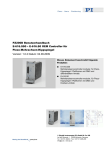
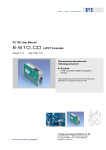
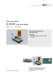
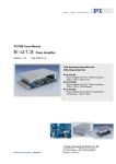
PZ200E User Manual
E-616.SS0 • E-616.S0 OEM Controller for
Piezo Multi-Axis Tip/Tilt Platforms
Release: 1.0.2 Date: 4.09.2009
This document describes the following
products:
■
E-616.SS0
Multi-Channel Servo-Controller Module for Piezo
Tip/Tilt Platforms with SGS and Based on
Differential Drive
■
E-616.S0
Multi-Channel Servo-Controller Module for Piezo
Tip/Tilt Platforms with SGS and Based on Tripod
Drive
© Physik Instrumente (PI) GmbH & Co. KG
Auf der Römerstr. 1 ⋅ 76228 Karlsruhe, Germany
Tel. +49 721 4846-0 ⋅ Fax: +49 721 4846-299
[email protected] ⋅ www.pi.ws
Declaration of
Conformity
according to DIN EN ISO/IEC 17050:2005-01
Manufacturer:
Physik Instrumente (PI)
GmbH & Co. KG
Manufacturer´s Auf der Römerstrasse 1
D-76228 Karlsruhe,
Address:
Germany
The manufacturer hereby declares that the product
Controller for Piezo Multi-Axis Tip/Tilt Platforms
Product Name:
Model Numbers:
E-616
Product Options:
all
complies with the following European directives:
2006/95/EC, Low-voltage directive (LVD)
2004/108/EC, EMC Directive
The applied standards certifying the conformity are listed below.
Electromagnetic Emission:
EN 61000-6-3, EN 55011
Electromagnetic Immunity:
EN 61000-6-1
Safety (Low Voltage Directive):
EN 61010-1
Electrical equipment, which is intended to be integrated in other
electrical equipment, only conforms to the cited EMC Standards and
normative documents, if the user ensures a compliant connection
when implementing the total system. Possible necessary measures
are installation of the component in a suitable shielded enclosure and
usage of suitable connectors.
March 23, 2009
Karlsruhe, Germany
Dr. Karl Spanner
President
Physik Instrumente (PI) GmbH & Co. KG is the owner of the following company names and trademarks:
PI®, PIC®, PICMA®, PILine®, PIFOC®, PiezoWalk®, NEXACT®, NEXLINE®, NanoCube®,
NanoAutomation®
The following designations are protected company names or registered trademarks of third parties:
LabVIEW
The products described in this manual are in part protected by the following patents:
US-Patent No. 6,950,050
Copyright 2009 by Physik Instrumente (PI) GmbH & Co. KG, Karlsruhe, Germany.
The text, photographs and drawings in this manual enjoy copyright protection. With regard thereto,
Physik Instrumente (PI) GmbH & Co. KG reserves all rights. Use of said text, photographs and drawings
is permitted only in part and only upon citation of the source.
First printing 04.09.2009
Document Number PZ200E, KSch, Release 1.0.2
E-616_User_PZ200E102.doc
Subject to change without notice. This manual is superseded by any new release. The newest release is
available for download at www.pi.ws
About this Document
Users of this Manual
This manual is designed to help the reader to install and operate the E-616 OEM Controller for Piezo
Multi-Axis Tip/Tilt Platforms. It assumes that the reader has a fundamental understanding of basic servo
systems, as well as motion control concepts and applicable safety procedures.
Furthermore the manual describes the physical specifications of the E-616 OEM Controller for Piezo
Multi-Axis Tip/Tilt Platforms.
Conventions
The notes and symbols used in this manual have the following meanings:
WARNING
Calls attention to a procedure, practice or condition which, if not
correctly performed or adhered to, could result in injury or death.
DANGER
Indicates the presence of high voltage (> 50 V). Calls attention to a
procedure, practice or condition which, if not correctly performed or
adhered to, could result in injury or death.
!
CAUTION
Calls attention to a procedure, practice, or condition which, if not
correctly performed or adhered to, could result in damage to
equipment.
NOTE
Provides additional information or application hints.
Related Documents
The mechanics, submodules and the software tools which might be mentioned in this documentation are
described in their own manuals. Current releases can be downloaded from the PI Website as PDF files
(htt p://www .pi.ws). For updated releases contact your Physik Instrumente Sales Engineer or write
[email protected].
Contents
1
Introduction
1.1
1.2
1.3
1.4
1.5
1.6
6
Overview ............................................................................................. 6
Prescribed Use.................................................................................... 7
Safety Precautions .............................................................................. 7
Model Survey .................................................................................... 10
Optional Accessories for E-616......................................................... 11
Unpacking ......................................................................................... 11
2
Mounting of the E-616 Module
12
3
Starting Operation
13
3.1
3.2
Calibrated System ............................................................................. 13
Front and Rear Panel Elements ........................................................ 14
3.2.1
3.2.2
3.2.3
3.2.4
3.3
3.4
3.5
3.6
3.7
4
Open-Loop and Closed-Loop Operation ........................................... 19
Analog Control Input.......................................................................... 23
First Operation................................................................................... 24
Download of Analog GCS LabVIEW Driver Set ................................ 27
Monitor Signals.................................................................................. 28
Calibration
4.1
4.2
5
Front Panel of the E-616.SS0 Controller ............................................ 14
Rear Side of the E-616.SS0 Controller............................................... 15
Front Panel of the E-616.S0 Controller .............................................. 17
Rear Side of the E-616.S0 Controller ................................................. 18
Zero-Point Adjustment....................................................................... 31
Servo-Controller Dynamic Calibration ............................................... 35
System Description
5.1
5.2
31
39
The E-616.SS0x Controller ............................................................... 39
The E-616.S0x Controller.................................................................. 40
6
Troubleshooting
42
7
Customer Service
43
8
Old Equipment Disposal
44
9
Technical Data
9.1
9.2
9.3
9.4
9.5
45
Specifications .................................................................................... 45
Frequency Response Diagram.......................................................... 46
Block Diagram for E-616.SS0x.......................................................... 48
Block Diagram for E-616.S0x ............................................................ 50
Pin Assignments................................................................................ 52
9.5.1
9.5.2
9.5.3
9.5.4
PZT & Sensor Connector of the E-616.SS0 ....................................... 52
PZT & Sensor Connector of the E-616.S0 ......................................... 53
Pin Assignment of Rear Main Connector for E-616.SS0.................... 54
Pin Assignment of Rear Main Connector for E-616.S0 ...................... 55
Introduction
1
Introduction
1.1
Overview
The E-616 is an OEM controller module for piezo based tip/tilt mirrors and
tip/tilt platforms with high-resolution strain gauge sensors. A high peak
output power of 10 W per channel allows dynamic operation of the tip/tilt
mirrors for applications such as (laser) beam steering and stabilization.
Average output power is 5 W.
All multi-axis piezo tip/tilt mirrors of PI are designed as parallel-kinematics:
all actuators affect the same movable platform. Two orthogonal rotation
axes share a common pivot point. For position controlled S-330.xSD or
S-334.2SD tip/tilt mirrors the differential evaluation of two sensors per axis
provides an improved linearity and resolution. E-616 Controllers together
with tip/tilt platforms from PI make an ideally matched system and are
available in two versions:
■
E-616.S0 Controller OEM module for tip/tilt platforms based on tripod
design (e.g. S-325): the platform is equipped with three piezo
actuators spaced at 120° intervals
■
E-616.SS0 Controller OEM module for tip/tilt platforms based on
differential design (e.g. S-330 or S-334): four actuators operate in
push-pull mode
Internal Coordinate Transformation Simplifies Control of
Parallel Kinematics Designs
Parallel-kinematics require the transformation of the commanded tilt angles
into the corresponding linear motion of the individual actuators. In the
E-616.S0, this is taken care of by an integrated circuit for the S-325 tip/tilt
platforms featuring three actuators, eliminating the need of additional
external hardware or software. Additionally with the E-616.S0 all actuators
can be commanded by an offset-voltage simultaneously. As a result a
vertical motion, for example for optical path tuning, is obtained.
www.pi.ws
E-616 PZ200E Release 1.0.2
Page 6
Introduction
1.2
Prescribed Use
Based on their design and realization, E-616 OEM Controllers for Piezo
Multi-Axis Tip/Tilt Platforms are intended to drive capacitive loads, in the
present case, piezoceramic actuators. E-616 Controllers must not be used
for applications other than stated in this manual, especially not for driving
ohmic (resistive) or inductive loads.
Observe the safety precautions given in this User Manual.
The E-616 is a laboratory apparatus as defined by DIN EN 61010. It meets
the following minimum specifications for safe operation (any more stringent
specifications in the technical data table are, of course, also met):
1.3
■
Indoor use only
■
Altitude up to 2000 m
■
Temperature range 5°C to 40°C
■
Max. relative humidity 80% for temperatures up to 31°C, decreasing
linearly to 50% relative humidity at 40°C
■
Line voltage fluctuations not greater than ±10% of the line voltage
■
Transient overvoltages as typical for public power supply
Note: The nominal level of the transient overvoltage is the standing
surge voltage according to the overvoltage category II (IEC 60364-4443).
■
Degree of pollution: 2
Safety Precautions
Carefully read also the user manuals and / or technical notes of all other
components involved, as e.g. of mechanics and software.
Failure to heed warnings in this manual can result in bodily injury or
material damage or loss of warranty.
DANGER - HIGH VOLTAGE
E-616 Power Amplifiers output VERY HIGH VOLTAGES and HIGH
CURRENTS which can cause death or injury! Working with these
devices requires adequately trained and educated operating
personnel. Follow general accident prevention rules!
www.pi.ws
E-616 PZ200E Release 1.0.2
Page 7
Introduction
■
Do not touch the pins of the sub-D connector which carry the
piezo output voltage and the sensor signals. The high voltage
output may be active whenever the controller is turned on.
Voltages between -20 V and +120 V can be present on the sub-D
connector.
■
Be sure to connect pins A-32 and C-32 to a Protective Ground
DANGER
Procedures which require opening the case should be carried out by
authorized, qualified personnel only.
Disconnect the E-616 from power when opening the case, and when
resetting internal switches or jumpers.
When the E-616 must be operated with the case open, voltages of up
to 120 V can be exposed. Do not touch internal conductors.
CAUTION
The product described is an ESD-sensitive (electrostatic discharge
sensitive) device. Observe all precautions against static charge buildup
before handling these devices.
!
Avoid touching circuit components, pins and PCB traces. Discharge
any static charge you may have on your body by briefly touching a
conductive, grounded object before you touch any electronic assembly.
Pose PCBs only on conductive surfaces, such as ESD-safe transport
containers (envelopes, foam). Electronic subassemblies must always
be kept and transported/shipped in conductive packaging.
CAUTION - AIR CIRCULATION
Provide for sufficient ventilation. Insufficient air flow will cause
overheating and premature failure. For detailed information on
overheat protection see "Troubleshooting" (p. 42), second section.
CAUTION-RESONANT FREQUENCY
Most piezo actuators that can be connected to the E-616 can be
destroyed by uncontrolled oscillation near the mechanical resonant
frequency. If you observe resonance while configuring your system,
www.pi.ws
E-616 PZ200E Release 1.0.2
Page 8
!
!
Introduction
switch off power to the actuators concerned immediately and follow the
instructions in section "Dynamic Calibration (p. 35)".
!
CAUTION-CALIBRATION
!
CAUTION-SYSTEM ASSIGNMENT
!
CAUTION - V-MON-MEASUREMENT
If you inform PI about your application, your E-616 will be fully
calibrated before being shipped. Tip/tilt platform and controller are
matched and calibrated together. Do not interchange controller (whole
devices or individual modules) and/or tip/tilt platforms when they are
calibrated together. Respect the assignment of the tip/tilt platforms to
the controllers, as indicated by the serial numbers on the labels affixed
to the devices. Re-calibration should only be done by adequate trained
personnel and after consultation with PI. Otherwise preset data will be
lost. Only if an overflow LED (OFL1, OFL2) glows a zero-point
adjustment will be necessary.
Connect only a matching tip/tilt platform to the corresponding E-616
Controller version: tip/tilt platforms such as S-325.3SD (tripod design)
to E-616.S0x, SD-versions of S-330 series or S-334 tip/tilt platforms
(differential design) to E-616.SS0x.
Be sure to use an appropriate input impedance when you measure the
following monitor voltages on the rear 32-pin connector: V-MON-X
(pin A-4), V-MON-Y (pin A-12), and V-MON-1 to V-MON-3 (pins A-18,
C-18, A-16).
V-MON-X, V-MON-Y: Output impedance is 11 kΩ per channel
V-MON-1 to V-MON-3: Output impedance is 1 kΩ per channel
Your measurement device may get damaged if you measure without
appropriate input impedance.
!
www.pi.ws
CAUTION - SGS-MON-MEASUREMENT
Be sure to use an appropriate input impedance when you measure the
following monitor voltages on the rear 32-pin connector: SGS-MON-X
(pin C-14), SGS-MON-Y (pin A-14), and SGS-MON-1 to SGS-MON-3
(pins A-10, C-10, C-16).
SGS-MON-X, SGS-MON-Y: Output impedance is 50 Ω per channel
SGS-MON-1 to SGS-MON-3: Output impedance is 10 kΩ / 10 nF
Your measurement device may get damaged if you measure without
appropriate input impedance.
E-616 PZ200E Release 1.0.2
Page 9
Introduction
1.4
Model Survey
The following standard configurations of E-616 Controller modules are
available:
E-616.SS0
Multi-Channel Servo Controller / Driver for Piezo
Tip/Tilt Mirror Platforms with SGS and Differential
Drive
E-616.S0
Multi-Channel Servo Controller / Driver for Piezo
Tip/Tilt Mirror Platforms with SGS and Tripod Drive
Both versions are available with a housing as stand-alone bench-top device
(E-616.SS0G, E-616.S0G), see Figure 1 below:
Figure 1: Front panel of E-616.SxG benchtop controller
The bench-top devices are described in a separate manual (PZ219E). You
can download it from the PI website.
One E-802.55 servo-control module for each of the X- and Y-tilt axes is
integrated in the E-616 analog controllers. Find more information on these
servo-control modules in the separate User Manual (PZ150E, included in
the contents of delivery).
www.pi.ws
E-616 PZ200E Release 1.0.2
Page 10
Introduction
1.5
Optional Accessories for E-616
E-500.ACD
LabVIEW driver set for analog controllers, available free
of charge upon request
Computer control can be implemented using a DACboard in a PC to generate the analog input signal. PI
offers a LabVIEW driver set which can be used with
certain D/A boards. This driver set is compatible with the
PI General Command Set (GCS) LabVIEW driver set
available for all newer controllers from PI.
The PI Analog Controller drivers support all D/A converter
boards from National Instruments that are compatible
with DAQmx8.3. LabVIEW compatibility is given from
version 7.1 upwards.
The driver set is also available for download from the PI
website.
E-500.HCD
1.6
Access to HyperBit™ Functionality for Enhanced System
Resolution (Supports Certain D/A Boards). PI's patented
HyperBit™ technology for providing position resolution
higher than that of the D/A board is in the E-500.ACD
driver set. Activating HyperBit™ requires purchase of the
password, which can be obtained from PI under Order
No. E-500. HCD.
Unpacking
Unpack the E-616 OEM Controller for Piezo Multi-Axis Tip/Tilt Platforms
with care. Compare the contents against the items covered by the contract
and against the packing list.
The following components are included:
E-616.Sx
in ordered configuration
PZ200
User Manual for E-616.SS0/E-616.S0 (this document)
PZ150E
User Manual for E-802 Servo-Control Submodule
588
32-pin main connector (DIN 416123)
E500T0011
Technical Note, contains access information for
downloading the latest version of GCS LabVIEW driver
set for analog controllers
Inspect the contents for signs of damage. If parts are missing or you notice
signs of damage, contact PI immediately.
Save all packing materials in case the product need be shipped again.
www.pi.ws
E-616 PZ200E Release 1.0.2
Page 11
Mounting of the E-616 Module
2
Mounting of the E-616 Module
CAUTION - AIR CIRCULATION
Provide for sufficient ventilation. Insufficient air flow will cause
overheating and premature failure.
For detailed information on overheat protection see "Troubleshooting"
(p. 42), second section.
For mounting the E-616.Sx module proceed as follows:
1 Insert the module into an appropriate case. The rear 32-pin main
connector of the E-616 module can be connected to a suitable
power supply (12-30 V, 2 A) and control input signals via the
included multi-point socket (art. no. 588). For more information see
"Pin Assignment of the Main Rear Connector for E-616.SS0"
(p. 54) respectively"Pin Assignment of Rear Main Connector for
E-616.S0" (p. 55)
2
Be sure to connect pins A-32 and C-32 to a Protective Ground
3
Fix the module to the front panel using the four included crosshead screws, see Figure 2 below
Figure 2: Front panel of E-616, arrows indicate where to tighten the front
plate to an appropriate case
www.pi.ws
E-616 PZ200E Release 1.0.2
Page 12
!
Starting Operation
3
Starting Operation
3.1
Calibrated System
If an E-616 Controller is ordered together with a tip/tilt platform, the system
will be fully calibrated at PI according to your specifications before being
shipped, and will come with a calibration information sheet.
!
www.pi.ws
CAUTION-CALIBRATION
If you inform PI about your application, your E-616 will be fully
calibrated before being shipped. Tip/tilt platform and controller are
matched and calibrated together. Do not interchange controller (whole
devices or individual modules) and/or tip/tilt platforms when they are
calibrated together. Respect the assignment of the tip/tilt platforms to
the controllers, as indicated by the serial numbers on the labels affixed
to the devices. Re-calibration should only be done by adequate trained
personnel and after consultation with PI. Otherwise preset data will be
lost. Only if an overflow LED (OFL1, OFL2) glows a zero-point
adjustment will be necessary.
E-616 PZ200E Release 1.0.2
Page 13
Starting Operation
3.2
Front and Rear Panel Elements
3.2.1
Front Panel of the E-616.SS0 Controller
www.pi.ws
25-pin sub-D socket "PZT &
Sensor"
For connecting tip/tilt platforms with SGS
sensors and based on differential design as
e.g. those of the S-330 or S-334 series.
For pin assignment see "PZT & Sensor
Connection of the E-616.SS0 Controller"
(p. 52)
Zero 1 and Zero 2
potentiometers
For zero-point adjustment of the SGS-sensor
channels 1 and 2
"OFL1" and "OFL2" LED
Green light for overflow of the amplifier, see
"Zero-Point Adjustment" (p. 31) for more
information
"POWER" LED
Green light glows permanently, indicates
connection to power supply
E-616 PZ200E Release 1.0.2
Page 14
Starting Operation
NOTE
Note that sensor channel 3 (SGS-MON-3) and potentiometer Zero 3
are deactivated with the E-616 Controller based on differential drive.
NOTE
Overflow is possible in open-loop mode
In open-loop operation, exceeding the allowable control input range will
cause an overflow condition of the corresponding amplifier. In this case
the maximum amplifier output voltage is reached and cannot be
exceeded. For further information see sections "Analog Control Input"
(p. 23) respectively "Zero-Point Adjustment" (p. 31).
3.2.2
Rear Side of the E-616.SS0 Controller
The 32-pin connector comprises lines for:
■ Operating power input (DC-Input from 12 V to 30 V, 2 A)
■
www.pi.ws
V-MON-1 and V-MON-2 monitor channels carry one-hundredth of the
amplifier output for the X and Y tilt axes.(PA1, PA2, see "Block
Diagram for E-616.SS0" (p. 48))
E-616 PZ200E Release 1.0.2
Page 15
Starting Operation
■
V-MON-3 monitor channel carries one-hundredth of the fixed output
voltage of amplifier PA3, see "Block Diagram for E-616.SS0" (p. 48)
■
V-MON-X and V-MON-Y channels monitor the servo-control module
output for the X- and Y-tilt axes, see "Block Diagram for E-616.SS0"
(p. 48)
■
SGS-MON-1 and SGS-MON-2 channels monitor the sensor signals
of the two SGS sensor bridges, see "Block Diagram for E-616.SS0"
(p. 48)
■
SGS-MON-X and SGS-MON-Y channels monitor the differential
sensor signals of the X- and Y- tilt axes, exactly corresponding to
signals SGS-MON-1 and SGS-MON-2
■
Control inputs X-Input and Y-Input for tilt motion of the X- and Y-tilt
axes, see “Analog Control Input” (p. 23)
■
Servo-1 ON/OFF and Servo-2 ON/OFF for changing between openloop and closed-loop mode for the X- and Y-tilt axes "Open-Loop and
Closed-Loop Operation" (p. 19)
■
Overflow signals, see "Zero-Point Adjustment" (p. 31)
■
TTL signal for synchronizing, 200 kHz
For details on pin assignment see "Pin Assignment of the Main Rear
Connector for E-616.SS0" (p. 54)
www.pi.ws
E-616 PZ200E Release 1.0.2
Page 16
Starting Operation
3.2.3
Front Panel of the E-616.S0 Controller
www.pi.ws
25-pin sub-D socket "PZT &
Sensor"
For connection of a tip/tilt mirror with SGS
sensors and based on a tripod design.
For pin assignment see "PZT & Sensor
Connector of the E-616.S0" (p. 53)
Zero 1 to Zero 3
potentiometers
For zero-point adjustment of the sensor
channels 1, 2 and 3
"OFL1" and "OFL2" LED
Green light for overflow of the amplifier, see
"Zero-Point Adjustment" (p. 31) for more
information
"POWER" LED
Green light glows permanently, indicates
connection to power supply
E-616 PZ200E Release 1.0.2
Page 17
Starting Operation
NOTE
Overflow is possible in open-loop mode
In open-loop operation, exceeding the allowable control input range will
cause an overflow condition of the corresponding amplifier. In this case
the maximum amplifier output voltage is reached and cannot be
exceeded. For further information see sections "Analog Control Input"
(p. 23)respectively"Zero-Point Adjustment" (p. 31).
3.2.4
Rear Side of the E-616.S0 Controller
The 32-pin connector contains connections for:
■ Operating power input (DC-Input from 12 V to 30 V, 2 A)
www.pi.ws
■
V-MON-1 to V-MON-3 monitor channels carry one-hundredth of the
amplifier output (PA1, PA2, PA3 see "Block Diagram of the E-616.S0
Controller" (p. 50)) (channel-related, not axis-related)
■
V-MON-X and V-MON-Y channels monitor the servo-control module
output for the X and Y tilt axes, see "Block Diagram of the E-616.S0
Controller" (p. 50) (axis-related)
E-616 PZ200E Release 1.0.2
Page 18
Starting Operation
■
SGS-MON-1 to SGS-MON-3 monitor channels carry the signals of
the three SGS sensors, i.e. the channel-related input of the
transformation board, see"Block Diagram of the E-616.S0 Controller"
(p. 50) (channel-related, not axis-related)
■
SGS-MON-X and SGS-MON-Y channels monitor the transformed
sensor signals X-In and Y-In, see "Block Diagram of the E-616.S0
Controller" (p. 50), (axis-related)
■
Control inputs X-Input and Y-Input for tilt motion of the X and Y tilt
axes and Z-Offset for vertical motion, see “Analog Control Input”
(p. 23)
■
Servo-1 ON/OFF and Servo-2 ON/OFF for changing between openloop and closed-loop mode for the X and Y tilt axes "Open-Loop and
Closed-Loop Operation" (p. 19)
■
Overflow signals, see"Zero-Point Adjustment" (p. 31)
■
TTL signal for synchronizing, 200 kHz
For details on pin assignment see "Pin Assignment of Rear Main Connector
for E-616.S0" (p. 55)
NOTE
Note that the vertical motion commanded by the E-616 Controller for
tripod design (Z-Offset) always is in open-loop mode, independent from
the operation mode of the X and Y tilt axes.
3.3
Open-Loop and Closed-Loop Operation
DANGER
Procedures which require opening the case should be carried out by
authorized, qualified personnel only.
Disconnect the E-616 from power when opening the case, and when
resetting internal switches or jumpers.
When the E-616 must be operated with the case open, voltages of up
to 120 V can be exposed. Do not touch internal conductors.
www.pi.ws
E-616 PZ200E Release 1.0.2
Page 19
Starting Operation
CAUTION
The product described is an ESD-sensitive (electrostatic discharge
sensitive) device. Observe all precautions against static charge buildup
before handling these devices.
Avoid touching circuit components, pins and PCB traces. Discharge
any static charge you may have on your body by briefly touching a
conductive, grounded object before you touch any electronic assembly.
Pose PCBs only on conductive surfaces, such as ESD-safe transport
containers (envelopes, foam). Electronic subassemblies must always
be kept and transported/shipped in conductive packaging.
Open-Loop Operation
All E-616 versions can be operated in open-loop mode. Open-loop
operation of the tip/tilt platform axes means that any control input provided
by the user (X-Input, Y-Input and with E-616.S0 Z-Offset as well)
determines the output voltage directly.
Closed-Loop Operation
Closed-loop operation requires a position sensor and a servo module. Any
control input provided by the user determines the position of the tip/tilt
platform axes. The output voltage required to reach this target position is
calculated internally by the servo-loop, based on the given target and the
feedback of the position sensors. In position-control operation non-linearity
and drift effects are compensated.
E-616 Controllers feature one E-802.55 servo-control module per tilt axis.
You find a description of the servo-control modules in the E-802 User
Manual PZ150E.
Selection of Open-Loop and Closed-Loop Operation
All E-616 Controllers are set to closed-loop mode and are calibrated. To
change to open-loop mode open the device and use the internal DIP
switches. If these switches are set to open-loop mode, an external selection
of the operation mode is possible using the rear 32-pin connector.
To open the device proceed as follows:
www.pi.ws
■
Disconnect the device from line voltage by removing the external
power supply from line voltage
■
To remove the heat sink of the E-616 Controller module unscrew the
six labeled cross-head screws, see Figure 3 below
■
Do also unscrew the two labeled cross-head screws on the front of
the module, see Figure 4 below
E-616 PZ200E Release 1.0.2
Page 20
!
Starting Operation
Figure 3: Fixation of heat sink to E-616 Controller module side
Figure 4: Fixation of heat sink to E-616 Controller module front
www.pi.ws
E-616 PZ200E Release 1.0.2
Page 21
Starting Operation
The DIP switches for operating mode selection are now accessible, see
Figure 5 below.
Figure 5: DIP-switch and servo control modules E-802.55 in the E-616
Controller module
■
To change from closed-loop (servo-on) mode to open-loop (servo-off)
mode use DIP switch 1 for servo-control module 1 and DIP switch 2
for servo-control module 2.
Servo-control module 1 is assigned to X tilt axis, servo-control module 2 is
assigned to Y tilt axis.
To deactivate control of a tilt axis in principle set the corresponding DIP
switch from On to Off.
NOTE
Separate Control of the Tilt Axes
Separate control of each of the two tilt axes is possible for both
versions of the E-616 Controller. For example X tilt axis can be
operated in closed-loop mode while Y tilt axis is in open-loop mode.
www.pi.ws
E-616 PZ200E Release 1.0.2
Page 22
Starting Operation
NOTE
Selection of Operating Mode by Rear 32-Pin Main
Connector
When DIP switches 1 and 2 are in OFF position then servo control can
be activated and deactivated by pins C-26 (Servo-1 OFF/ON) and A-26
(Servo-2 OFF/ON) of the rear 32-pin main connector. Use TTL signals
for these pins (0 V to 0.5 V = LOW = Servo ON; 3 V to 5 V = HIGH =
Servo OFF).
NOTE
Note that the vertical motion commanded by the E-616 Controller for
tripod design (Z-Offset) always is in open-loop mode, independent from
the operation mode of the X and Y tilt axes.
3.4
Analog Control Input
For all E-616 models tip/tilt motion of the mirror platform is commanded by
analog signals. Control input signals generated by external signal sources
are connected to pins A-20 (Input X), C-22 (Input Y) and with the E-616.S0
tripod controller to C-24 (Z-Offset).
Computer control can be implemented using a DAC-board in a PC to
generate the analog input signal. PI offers a LabVIEW driver set which can
be used with certain D/A boards. This driver set is compatible with the PI
General Command Set (GCS) driver set available for all newer controllers
from PI. A further option includes the patented HyperBit™ technology
providing enhanced system resolution.
Download instructions are in "Download of the GCS LabVIEW Driver Set for
Analog Controllers" (p. 27).
NOTE - RANGE OF CONTROL INPUT FOR
E-616.SS0 AND E-616.SS0G
By default E-616 Controllers are preset for closed-loop mode. There
are different ranges of control input for closed-loop and for open-loop
mode.
For E-616.SS0 and E-616.SS0G following control input ranges are
valid:
■
X- Input, Y-Input, closed-loop: 0 to +10 V
■
X-Input, Y-Input, open-loop: -2 to +12 V
If you apply voltage exceeding these ranges the overflow LEDs glow.
www.pi.ws
E-616 PZ200E Release 1.0.2
Page 23
Starting Operation
NOTE - CONTROL INPUT RANGE FOR E-616.S0
AND E-616.S0G
With calibration of the tripod controllers E-616.S0x an offset voltage is
applied to the piezo actuators to achieve a maximum tip/tilt range.
By default E-616 Controllers are preset for closed-loop mode. There
are different ranges of control input for closed-loop and for open-loop
mode.
For E-616.S0 and E-616.S0G following control input ranges are valid:
Closed-loop mode for tilt axes:
■
X- Input, Y-Input: -5 to +5 V
■
Z-Offset: -3.0 to +3.0 V
Open-loop mode for tilt axes:
■
X-Input, Y-Input: -7 to +7 V
■
Z-Offset: -3.0 to +3.0 V
If you apply voltage exceeding these ranges the overflow LEDs glow.
3.5
First Operation
DANGER - HIGH VOLTAGE
E-616 Power Amplifiers output VERY HIGH VOLTAGES and HIGH
CURRENTS which can cause death or injury! Working with these
devices requires adequately trained and educated operating
personnel. Follow general accident prevention rules!
www.pi.ws
■
Do not touch the pins of the sub-D connector which carry the
piezo output voltage and the sensor signals. The high voltage
output may be active whenever the controller is turned on.
Voltages between -20 V and +120 V can be present on the sub-D
connector.
■
Be sure to connect pins A-32 and C-32 to a Protective Ground
E-616 PZ200E Release 1.0.2
Page 24
Starting Operation
!
CAUTION
The product described is an ESD-sensitive (electrostatic discharge
sensitive) device. Observe all precautions against static charge buildup
before handling these devices.
Avoid touching circuit components, pins and PCB traces. Discharge
any static charge you may have on your body by briefly touching a
conductive, grounded object before you touch any electronic assembly.
Pose PCBs only on conductive surfaces, such as ESD-safe transport
containers (envelopes, foam). Electronic subassemblies must always
be kept and transported/shipped in conductive packaging.
!
CAUTION - AIR CIRCULATION
!
CAUTION-RESONANT FREQUENCY
!
CAUTION-SYSTEM ASSIGNMENT
!
CAUTION - V-MON-MEASUREMENT
Provide for sufficient ventilation. Insufficient air flow will cause
overheating and premature failure.
For detailed information on overheat protection see "Troubleshooting"
(p. 42), second section.
Most piezo actuators that can be connected to the E-616 can be
destroyed by uncontrolled oscillation near the mechanical resonant
frequency. If you observe resonance while configuring your system,
switch off power to the actuators concerned immediately and follows
the instructions given in section "Dynamic Calibration" (p. 35).
Connect only a matching tip/tilt platform to the corresponding E-616
Controller version: tip/tilt platforms such as S-325.3SD (tripod design)
to E-616.S0x, SD-versions of S-330 series or S-334 tip/tilt platforms
(differential design) to E-616.SS0x.
Be sure to use an appropriate input impedance when you measure the
following monitor voltages on the rear 32-pin connector: V-MON-X
(pin A-4), V-MON-Y (pin A-12), and V-MON-1 to V-MON-3 (pins A-18,
C-18, A-16).
V-MON-X, V-MON-Y: Output impedance is 11 kΩ per channel
V-MON-1 to V-MON-3: Output impedance is 1 kΩ per channel
www.pi.ws
E-616 PZ200E Release 1.0.2
Page 25
Starting Operation
Your measurement device may get damaged if you measure without
appropriate input impedance.
CAUTION - SGS-MON-MEASUREMENT
Be sure to use an appropriate input impedance when you measure the
following monitor voltages on the rear 32-pin connector: SGS-MON-X
(pin C-14), SGS-MON-Y (pin A-14), and SGS-MON-1 to SGS-MON-3
(pins A-10, C-10, C-16).
SGS-MON-X, SGS-MON-Y: Output impedance is 50 Ω per channel
SGS-MON-1 to SGS-MON-3: Output impedance is 10 kΩ / 10 nF
Your measurement device may get damaged if you measure without
appropriate input impedance.
Do not interchange controller (whole devices or individual modules) and / or
tip/tilt platforms if they are matched and calibrated together. Controller and
tip/tilt platforms that were calibrated together are not exchangeable. The
serial number of the corresponding tip/tilt platform is given on the calibration
label of the E-616.
The device is factory set to open-loop mode.
Getting Started
1 Connect the controller via its rear 32-pin main connector to your
case using the included 32-pin multi-point socket connector
(art. no. 588). To do so consider the corresponding pin assignment,
see "Pin Assignment of the Rear Main Connector for E-616.SS0"
(p. 54) respectively "Pin Assignment of the Rear Main Connector
for E-616.S0" (p. 55) and connect pins A-32 and C-32 to a
Protective Ground
www.pi.ws
2
Connect the E-616 to the tip/tilt platform via the 25-pin sub-D
socket on its front panel
3
Connect the multi-point socket connector to an external power
supply via pins A-6 and A-8 respectively via pins C-6 and C-8 for
power supply, and connect the power supply to the line voltage.
Steady glowing of the green Power LED indicates readiness for
operation
4
To cause tip/tilt motion of the X- respectively Y-axis apply the
following control input signals to pins A-20 (X-Input) respectively
C-22 (Y-Input):
E-616 PZ200E Release 1.0.2
Page 26
!
Starting Operation
with E-616.SS0 from 0 V to +10 V,
with E-616.S0 from -5 V to + 5 V
If at least one of the green overflow-LEDs glows, then a zero-point
adjustment is necessary. Follow the instructions for zero-point
adjustment, see “Zero-Point Adjustment in Closed-loop Operation
with E-616 Controllers” (p. 31)
NOTE
To reduce disturbances by signal frequencies of other devices the E616 Controllers can be supplied with a 200 kHz TTL signal for
synchronization. This can be necessary for example if you use
measuring boards or if you operate another E-616 Controller.
3.6
Download of Analog GCS LabVIEW Driver Set
Updated releases of GCS LabVIEW drivers for analog controllers from PI
and the corresponding manuals are available for download at www.pi.ws.
While the manuals are freely accessible, you need a password for the
software download. This password is provided in the E500T0011 Technical
Note delivered with the controller.
To download from the PI Website, proceed as follows:
1
On the www.pi.ws front page, click on "Download/Support" in the
"Service" section on the left
2
On the "Download/Support" page, click on "Manuals and Software
Downloads"
3
On the "PI Download Server" page, enter the Username and the
Password which are provided in the separate Technical Note and
click on "Login"
4
Click on "Download" in the navigation bar across the top
5
Click on the "E Piezo Drivers & Nanopositioning" category
6 Click on "E-500"
7 Click on "Software" (if you click on "Documents" you will get the
latest manuals)
8 Click the "Download " button below the latest CD mirror (includes
the manuals that were with the release)
www.pi.ws
E-616 PZ200E Release 1.0.2
Page 27
Starting Operation
3.7
Monitor Signals
CAUTION - V-MON-MEASUREMENT
Be sure to use an appropriate input impedance when you measure the
following monitor voltages on the rear 32-pin connector: V-MON-X
(pin A-4), V-MON-Y (pin A-12), and V-MON-1 to V-MON-3 (pins A-18,
C-18, A-16).
V-MON-X, V-MON-Y: Output impedance is 11 kΩ per channel
V-MON-1 to V-MON-3: Output impedance is 1 kΩ per channel
Your measurement device may get damaged if you measure without
appropriate input impedance.
Monitoring the Output Voltage
The monitor channels of the rear main connector display the output voltage
of the servo-control modules as well as the output voltage of the amplifiers.
Be sure to choose an appropriate input impedance for your measurement
device when you measure the monitor voltage!
The output voltage of both servo-control modules is axis-related for
E-616.SS0 and for E-616.S0. The corresponding monitor voltages are
displayed by pins A-4 (V-MON-X) and A-12 (V-MON-Y) of the 32-pin
connector. The amplifiers multiply the servo-control output voltage by 10.
With the E-616.S0 Controller the axis-related V-MON signal is transformed
to a channel-related voltage first.
Monitor channels of the amplifier output voltage:
■
E-616.SS0:
The amplifiers PA1 and PA2 are assigned to the tilt axes in a one-toone ratio, whereas the output of amplifier PA3 is set fixed to 100 V.
The monitor channels V-MON-1 to V-MON-3 display one-hundredth
of the actual output voltage:
V-MON-1 is assigned to pin A-18 and amplifier PA1
V-MON-2 is assigned to pin C-18 and amplifier PA2
V-MON-3 is assigned to pin A-16 and amplifier PA3
www.pi.ws
E-616 PZ200E Release 1.0.2
Page 28
!
Starting Operation
■
E-616.S0:
The three amplifier channels are related to the tilt axes X and Y via
the transformation unit. The output voltage (V-MON-1 to V-MON-3) is
split by a voltage divider and one-hundredth of the actual output
voltage is displayed as V-MON signal:
V-MON-1 is assigned to pin A-18 and amplifier PA1
V-MON-2 is assigned to pin C-18 and amplifier PA2
V-MON-3 is assigned to pin A-16 and amplifier PA3
The channel-related monitor signals V-MON-1, V-MON-2 and
V-MON-3 are calculated by the axis-related signals V-MON-X and
V-MON-Y as follows:
V-MON-1 = 0.1 Y
V-MON-2 = 0.1 (+0.867 X - 0.5 Y)
V-MON-3 =0.1 (-0.867 X - 0.5 Y)
where:
X = V-MON-X (X-Out)
Y = V-MON-Y (Y-Out)
!
CAUTION - SGS-MON-MEASUREMENT
Be sure to use an appropriate input impedance when you measure the
following monitor voltages on the rear 32-pin connector: SGS-MON-X
(pin C-14), SGS-MON-Y (pin A-14), and SGS-MON-1 to SGS-MON-3
(pins A-10, C-10, C-16).
SGS-MON-X, SGS-MON-Y: Output impedance is 50 Ω per channel
SGS-MON-1 to SGS-MON-3: Output impedance is 10 kΩ / 10 nF
Your measurement device may get damaged if you measure without
appropriate input impedance.
Monitoring the Sensor Signals
The sensor signals can be displayed related to channels (SGS-MON-1,
SGS-MON-2 and with E-616.S0 SGS-MON-3) and related to axes
(SGS-MON-X, SGS-MON-Y). The corresponding monitor channels are
available on the rear 32-pin main connector. Be sure to choose an
appropriate input impedance for your measurement device when you
measure the monitor voltage!
www.pi.ws
E-616 PZ200E Release 1.0.2
Page 29
Starting Operation
■
E-616.SS0:
The sensor channels can be assigned to the tilt axes X and Y in a
one-to-one ratio. Therefore SGS-MON-1 equals SGS-MON-X,
SGS-MON-2 equals SGS-MON-Y.
Channels SGS-MON-X (pin C-14) and SGS-MON-Y (pin A-14)
display the differential sensor signals for the X- and the Y-axis. Each
sensor signal is based on a pair of sensors, each pair is assigned to
the corresponding tilt axis.
■
E-616.S0:
A transformation unit connects the three sensor channels and both tilt
axes.
The sensor monitor channels SGS-MON-1 (pin A-10), SGS-MON-2
(pin C-10) and SGS-MON-3 (pin C-16) display the signals of the
sensors attached to the piezo actuators.
The sensor monitor signals SGS-MON-X (pin C-14) and
SGS-MON-Y (pin A-14) display the position of the tilt axes calculated
by the transformation unit.
The axis-related sensor signals SGS-MON-X and SGS-MON-Y are
derived from the channel-related sensor signals as follows:
SGS-MON-X = 0.867 (S2 -S3)
SGS-MON-Y = S1 - 0.5 (S2+S3)
where:
S1 = SGS-MON-1 (sensor signal 1)
S2 = SGS-MON-2 (sensor signal 2)
S3 = SGS-MON-3 (sensor signal 3)
www.pi.ws
E-616 PZ200E Release 1.0.2
Page 30
Calibration
4
Calibration
4.1
Zero-Point Adjustment
NOTE
Zero-Point Adjustment Only in Case of Overflow
Performing a zero-point adjustment is only required when at least one
of the overflow LEDs (OFL1, OFL2) glows!
A proper zero-point adjustment is precondition for complete expansion of
the piezo actuators over the maximum tilt range. Performing zero-point
adjustment excludes exceeding the possible amplifier output range. Thus
an overflow of the amplifier is prevented.
Variation of temperature between calibration and operation of the controller
may require a zero-point adjustment. The green overflow LEDs on the front
panel indicate whether a zero-point adjustment must be performed.
To adjust the zero-point use the three Zero 1 to Zero 3 potentiometers on
the front panel, see Figure 6 below. These potentiometers shift the signal
voltage of the sensor output (SGS-MON) and in closed-loop mode the
servo-control output (V-MON-X, V-MON-Y) as well as the amplifier output
(V-MON-1, V-MON-2 and with E-616.S0) is shifted additionally.
With the E-616.SS0 Controller for tip/tilt platforms based on differential drive
potentiometer Zero 3 is deactivated since there is no third sensor channel.
www.pi.ws
E-616 PZ200E Release 1.0.2
Page 31
Calibration
Figure 6: Potentiometers Zero 1 to Zero 3 for zero-point adjustment, OFL
and Power LEDs
CAUTION - V-MON-MEASUREMENT
Be sure to use an appropriate input impedance when you measure the
following monitor voltages on the rear 32-pin connector: V-MON-X
(pin A-4), V-MON-Y (pin A-12), and V-MON-1 to V-MON-3 (pins A-18,
C-18, A-16).
V-MON-X, V-MON-Y: Output impedance is 11 kΩ per channel
V-MON-1 to V-MON-3: Output impedance is 1 kΩ per channel
Your measurement device may get damaged if you measure without
appropriate input impedance.
The device is shipped calibrated and factory set to closed-loop operation.
Following instructions refer to zero-point adjustment for activated closedloop mode.
For zero-point adjustment proceed as follows:
www.pi.ws
E-616 PZ200E Release 1.0.2
Page 32
!
Calibration
■
With E-616.SS0:
1
Display the monitor signal V-MON of the amplifier channel with an
overflow (V-MON-1, V-MON-2)
2
To avoid an offset to the sensor signals caused by hysteresis
effects perform a complete tip/tilt motion of both tilt axes:
Apply a control input signal in the range from 0 V to +10 V to
X-Input respectively to Y-Input
3
Apply a control input voltage of 0 V to X-Input and Y-Input, to set
the platform back to its initial position
4
Adjust the corresponding Zero potentiometer until you obtain 0 V
as V-MON-signal (corresponds to 0 V amplifier output voltage)
5
Now change the control input signal for X-Input respectively
Y-Input in the range from 0 V to +10 V
The overflow LEDs should no longer glow. Permanent glow may indicate
failure of the device.
■
With E-616.S0:
1
Display the monitor signal V-MON of the amplifier channel with an
overflow (V-MON-1, V-MON-2, V-MON-3)
2
To avoid an offset to the sensor signals caused by hysteresis
effects perform a complete contraction / expansion cycle by
commanding a vertical motion. Apply a control input signal with a
voltage range from -3.0 V to +3.0 V to Z-Offset (pin C-24)
3
Apply a control input voltage of 0 V to Z-Offset
4
Apply a control input voltage of 0 V to X-Input and Y-Input, to set
the platform back to its initial position
5
Adjust the Zero potentiometer corresponding to the chosen V-MON
channel until you obtain +0.5 V as V-MON-signal (corresponds to
+50 V amplifier output voltage) - repeat this procedure for each of
the three V-MON channels
6
Now change the control input signal for X-Input and Y-Input in the
range from -5 V to +5 V
The overflow LEDs should no longer glow. Permanent glow may indicate
failure of the device.
www.pi.ws
E-616 PZ200E Release 1.0.2
Page 33
Calibration
Zero-Point Adjustment in Open-Loop Mode
CAUTION - SGS-MON-MEASUREMENT
Be sure to use an appropriate input impedance when you measure the
following monitor voltages on the rear 32-pin connector: SGS-MON-X
(pin C-14), SGS-MON-Y (pin A-14), and SGS-MON-1 to SGS-MON-3
(pins A-10, C-10, C-16).
SGS-MON-X, SGS-MON-Y: Output impedance is 50 Ω per channel
SGS-MON-1 to SGS-MON-3: Output impedance is 10 kΩ / 10 nF
Your measurement device may get damaged if you measure without
appropriate input impedance.
NOTE
To avoid an overflow of the amplifier in open-loop mode do not exceed
the allowable control input range.
Zero-point adjustment can be performed in open-loop mode as well.
To do so proceed as follows:
■
With E-616.SS0:
1
Display the sensor monitor signal SGS-MON of the sensor channel
to be adjusted (SGS-MON-1, SGS-MON-2)
2
To avoid an offset to the sensor signals caused by hysteresis
effects perform a complete tilt motion of both tilt axes: Apply a
control input range from -2 V to +12 V to X-Input respectively to
Y-Input
3
Apply a control input voltage of 0 V for X-Input and Y-Input, to set
the platform back to its initial position
4
Adjust the corresponding Zero potentiometer until you obtain 0 V
as SGS-MON signal
The OFL LEDs no longer glow if you change to closed-loop mode.
■
With E-616.S0:
1
www.pi.ws
Display sensor monitor signal SGS-MON of the sensor channel to
be adjusted (SGS-MON-1, SGS-MON-2, SGS-MON-3)
E-616 PZ200E Release 1.0.2
Page 34
!
Calibration
2
To avoid an offset to the sensor signals caused by hysteresis
effects perform a complete contraction / expansion cycle by
commanding a vertical motion. Apply a voltage range from -3.0 V
to +3.0 V to Z-Offset (pin C-24)
3
Apply a control input voltage of 0 V to Z-Offset
4
Apply a control input voltage of 0 V for X-Input and Y-Input, to set
the platform back to its initial position
5
Adjust the Zero potentiometer corresponding to the chosen
SGS-MON channel until you obtain about +5 V as SGS-MONsignal - repeat this procedure for each of the three SGS-MON
channels
The OFL LEDs no longer glow if you change to closed-loop mode.
4.2
Servo-Controller Dynamic Calibration
DANGER
Procedures which require opening the case should be carried out by
authorized, qualified personnel only.
Disconnect the E-616 from power when opening the case, and when
resetting internal switches or jumpers.
When the E-616 must be operated with the case open, voltages of up
to 120 V can be exposed. Do not touch internal conductors.
!
CAUTION
The product described is an ESD-sensitive (electrostatic discharge
sensitive) device. Observe all precautions against static charge buildup
before handling these devices.
Avoid touching circuit components, pins and PCB traces. Discharge
any static charge you may have on your body by briefly touching a
conductive, grounded object before you touch any electronic assembly.
Pose PCBs only on conductive surfaces, such as ESD-safe transport
containers (envelopes, foam). Electronic subassemblies must always
be kept and transported/shipped in conductive packaging.
Dynamic calibration is necessary when the response time of the actuators
has increased, in case of overshoot or when the mechanics starts
www.pi.ws
E-616 PZ200E Release 1.0.2
Page 35
Calibration
oscillating. A change of applied load is the cause most often. Dynamic
calibration adjusts servo parameters such as P-term, I-Term and the notch
filter frequency of the integrated E-802.55 servo-control modules.
To adjust servo-control parameters proceed as follows:
www.pi.ws
1
Disconnect the device from power supply
2
To remove the heat sink of the E-616 Controller module unscrew
the six labeled cross-head screws, see Figure 7 below
3
Tune the corresponding potentiometers, see Figure 8.
To do so read Section 3.2 "Equipment Needed for Calibration" and
Section 4 "Dynamic Calibration" in the servo-control module User
Manual (PZ150E) for more details.
E-616 PZ200E Release 1.0.2
Page 36
Calibration
Figure 7: Fixation of the heat sink to the E-616 Controller module
www.pi.ws
E-616 PZ200E Release 1.0.2
Page 37
Calibration
Figure 8: Assignment of potentiometers to E-802.55 servo control modules
Assignment of potentiometer to function:
P1
P2
P3
P4
P5
P6
www.pi.ws
Slew Rate Limitation
Loop Gain (P-Term)
Integration Time Constant (I-Term)
Notch Frequency
is factory set for internal use, not to be changed
is factory set for internal use, not to be changed
E-616 PZ200E Release 1.0.2
Page 38
System Description
5
System Description
5.1
The E-616.SS0x Controller
The E-616.SS0 controller module and the E-616.SS0G bench-top controller
are designed for tip/tilt platforms based on differential drive. The differential
drive of the S-330 and S-334 series tip/tilt platforms is based on two pairs of
actuators operating in push-pull mode to realize tilt motion. Each pair of
actuators is interconnected electrically so that one actuator expands while
the other contracts. With this principle of operation, pure vertical motion in
the Z-axis is not possible.
Each pair of actuators, i.e. each tilt axis, is assigned to one E-802.55 servocontrol module, to one sensor channel and to one amplifier channel. To
bring both axes in their initial position the output of the third amplifier
channel is fixed to 100 V.
The following assignment is valid for E-616.SS0x Controllers:
■
X tilt axis:
Control input:
Sensor monitor signal:
One tenth of internal
control voltage:
One-hundredth of
amplifier output voltage:
Servo control:
Overflow display:
Zero-point adjustment:
■
V-MON-X
V-MON-1
Servo-control module 1
OFL 1
Potentiometer Zero 1
Y tilt axis:
Control input:
Sensor monitor signal:
One tenth of internal
control voltage:
One-hundredth of
amplifier output voltage:
Servo control:
Overflow display:
Zero-point adjustment:
www.pi.ws
X-Input
SGS-MON-1 (equals SGS-MON-X)
Y-Input
SGS-MON-2 (equals SGS-MON-Y)
V-MON-Y
V-MON-2
Servo-control module 2
OFL 2
Potentiometer Zero 2
E-616 PZ200E Release 1.0.2
Page 39
System Description
5.2
The E-616.S0x Controller
The E-616.S0 controller module and the E-616.S0G bench-top controller
are designed for open-loop and closed-loop control of the S-325 series
tip/tilt platforms. These tip/tilt platforms are driven by three piezo actuators
arranged symmetrically around the center point of the mirror platform. The
controller features two servo-control modules for both tip/tilt axes as well as
one sensor channel and one amplifier channel for each of the three
actuators.
The combination of this controller version with an S-325 tip/tilt platform
offers the following advantages compared to systems based on differential
drive: firstly internal coordinate transformation facilitates direct commanding
of angles without any calculation efforts for the user. Secondly a
simultaneous vertical motion of the three actuators is possible.
NOTE
Note that the vertical motion commanded by the E-616 Controller for
tripod design (Z-Offset) always is in open-loop mode, independent from
the operation mode of the X and Y tilt axes.
Coordinate Transformation
The E-616.S0x Controller is designed to command S-325 series tip/tilt
platforms based on a tripod design. This controller version integrates a
circuit performing transformation of the commanded tilt angles into
corresponding linear motion of the individual actuators. The three actuators
are supplied by corresponding amplifier output voltage. A complicated
external calculation of the linear motion of the three actuators is omitted.
Due to the internal transformation unit of E-616.S0 controllers there is no
one-to-one assignment of tilt axes to sensor and amplifier channels.
Multiple amplifiers and multiple sensors can be involved in the motion of
one tilt axis, just as one amplifier or one sensor can participate in the
motion of more than one tilt axis.
Therefore the axis-related sensor signals (SGS-MON-X, SGS-MON-Y) are
calculated from the channel-related sensor signals (SGS-MON-1 to
SGS-MON-3).
This is done applying following formulas:
SGS-MON-X = 0.867 (S2 -S3)
SGS-MON-Y = S1 - 0.5 (S2+S3)
www.pi.ws
E-616 PZ200E Release 1.0.2
Page 40
System Description
where:
S1 = SGS-MON-1 (sensor signal 1)
S2 = SGS-MON-2 (sensor signal 2)
S3 = SGS-MON-3 (sensor signal 3)
Monitor signals of the amplifier output voltage (V-MON-1 to V-MON-3) are
calculated using the output voltage of the axis-related servo-control
modules (V-MON-X, V-MON-Y).
Calculation is performed using the following formulas:
V-MON-1 = 0.1 Y
V-MON-2 = 0.1 (+0.867 X - 0.5 Y)
V-MON-3 = 0.1 (-0.867 X - 0.5 Y)
where:
X = V-MON-X (X-Out)
Y = V-MON-Y (Y-Out)
Commanding Vertical Motion
With the E-616.S0x, vertical motion can be commanded using Z-Offset,
irrespective of the current operating mode of the tilt axes.
Note that tilt angle and vertical motion are interdependent. Values for
nominal tilt motion respectively for nominal vertical motion in the data table
of the tripod tip/tilt platforms (User Manual PZ148E for S-325 series tip/tilt
platforms) refer to pure nominal tilt motion respectively to pure nominal
vertical motion.
To calculate the actual possible tip/tilt motion and vertical motion read
Section 5 "Working Principle" of User Manual PZ148E for S-325 tip/tilt
mirrors.
Note: the maximum control input for Z-Offset ranges from -3.0 V to +3.0 V
without any additional tip/tilt motion. Z-Offset input is multiplied by a gain
of 20.
www.pi.ws
E-616 PZ200E Release 1.0.2
Page 41
Troubleshooting
6
Troubleshooting
Positioner does not move.
Cables not connected properly:
■ Check the connecting cables.
Check whether the allowable control input range was met:
■
E-616.SS0 / E-616.SS0G:
X- Input, Y-Input, closed-loop: 0 to +10 V
X-Input, Y-Input, open-loop: -2 to +12 V
■
E-616.S0 / E-616.S0G:
Closed-loop mode of tilt axes:
X- Input, Y-Input: -5 to +5 V
Z-Offset: -3 to +3 V
Open-loop mode of tilt axes:
X-Input, Y-Input: -7 to +7 V
Z-Offset: -3 to +3 V
The E-616 amplifier output channel is deactivated
If the internal temperature goes out of range (75 °C / 167 °F) the voltage
output will be deactivated. The tip/tilt platform stops moving. After a coolingdown period, at a hardware temperature of 60 °C / 140 °F, the voltage
output is reactivated automatically.
How to avoid overheating:
■ To avoid overheating, reduce the ambient temperature. Note that the
difference in ambient temperature and hardware temperature is
about 20 Kelvin (1 Kelvin corresponds to 1 °C, a temperature
difference of 20 Kelvin equals a difference of 36 °F).
www.pi.ws
■
E-616.Sx OEM Controller modules need to be installed with an
appropriate air circulation area. Forced air cooling must be provided
to prevent internal heat build-up.
■
Place the E-616 bench-top controllers in a location with adequate
ventilation to prevent internal heat build-up. Allow at least 10 cm
(4 inches) clearance from the top and the rear of the unit and 5 cm
(2 inches) from each side. If this is not possible reduce the ambient
temperature.
E-616 PZ200E Release 1.0.2
Page 42
Customer Service
7
Customer Service
Call your PI representative or write to [email protected]; please have the following
information about your system ready:
www.pi.ws
■
Product codes and serial numbers of all products in the system
■
Current firmware version of the controller (if present)
■
Version of drivers and / or host software (if present)
■
Operating system on host PC (if present)
E-616 PZ200E Release 1.0.2
Page 43
Old Equipment Disposal
8
Old Equipment Disposal
In accordance with EU directive 2002 / 96 / EC (WEEE), as of 13 August
2005, electrical and electronic equipment may not be disposed of in the
member states of the EU mixed with other wastes.
To meet the manufacturer’s product responsibility with regard to this
product, Physik Instrumente (PI) GmbH & Co. KG will ensure
environmentally correct disposal of old PI equipment that was first put into
circulation after 13 August 2005, free of charge.
If you have such old equipment from PI, you can send it to the following
address postage-free:
Physik Instrumente (PI) GmbH & Co. KG
Auf der Römerstr. 1
76228 Karlsruhe, Germany
www.pi.ws
E-616 PZ200E Release 1.0.2
Page 44
Technical Data
9
Technical Data
9.1
Specifications
E-616.S0
E-616.SS0
Function
Controller for piezo tip/tilt
mirror systems with strain
gauge sensors, tripod drive
Controller for piezo tip/tilt mirror
systems with strain gauge
sensors, differential drive
Tilt axes
2
2
Servo characteristics
P-I (analog), notch filter
P-I (analog), notch filter
Sensor type
SGS
SGS
Sensor channels
3
2
Ext. synchronization
200 kHz TTL
200 kHz TTL
Control input voltage
range
X-, Y- tilt axes:
-7 V to +7 V
Z-Offset: -3 V to +3 V
-2 V to +12 V
Output voltage range
-20 V to +120 V
-20 V to +120 V
Amplifier channels
3
3
Peak output power per
channel
10 W
10 W
Average output power
per channel
5W
5W
Peak current
100 mA
100 mA
Average current per
channel
50 mA
50 mA
Current limitation
Short-circuit-proof
Short-circuit-proof
Voltage gain
X-, Y- tilt axes: 10
Z-Offset: 20
10
Amplifier bandwidth,
small signal
3 kHz
3 kHz
Amplifier bandwidth,
large signal
See frequency diagram
See frequency diagram
Ripple, noise, 0 to 100
kHz
<20 mVpp
<2 mVrms
<20 mVpp
<2 mVrms
Amplifier resolution
<1 mV
<1 mV
Sensor
Amplifier
www.pi.ws
E-616 PZ200E Release 1.0.2
Page 45
Technical Data
Interfaces and
operation
Piezo / sensor
connector
25-pin sub-D connector
25-pin sub-D connector
Analog input
32-pin connector
32-pin connector
Sensor monitor output
0 to +10 V for nominal
displacement
0 to +10 V for nominal
displacement
Sensor monitor socket
32-pin connector
32-pin connector
Display
LEDs for Power and Overflow LEDs for Power and Overflow
Miscellaneous
9.2
Operating temperature
range
5 °C to 50 °C
5 °C to 50 °C
Overheat protection
Max. 75 °C, deactivation of
the piezo voltage output
Max. 75 °C, deactivation of the
piezo voltage output
Dimensions
186 mm x 128,4 mm x 10 HP
(incl. handle, 32-pin connector
& front panel; Euro card
format 3U/10HP)
186 mm x 128,4 mm x 10 HP
(incl. handle, 32-pin connector &
front panel; Euro card format
3U/10HP)
Mass
950 g
950 g
Operating voltage
12 to 30 V DC
12 to 30 V DC
Power consumption
30 W
30 W
Frequency Response Diagram
In order to achieve minimum distortion of the output waveform, it is
important to ensure that the amplitude of higher-frequency control input is
reduced in proportion to the fall-off of the output voltage at these
frequencies. For exact information on maximum operating frequency with a
given piezo load (capacitance), refer to the individual operating limit graphs
in Figure 9 below.
www.pi.ws
E-616 PZ200E Release 1.0.2
Page 46
Technical Data
Figure 9: PZT loads (open-loop), capacitance is measured in µF
Note that the operating limits of a given piezo amplifier depend on the
amplifier power, the amplifier design, and, of course, on the capacitance of
the piezo actuator. The capacitance of piezo ceramics changes significantly
with amplitude, temperature, and load-up to approximately 200 % of the
unloaded, small-signal capacitance at room temperature.
The following equations describe the relationship between (reactive) drive
power, actuator capacitance, operating frequency and drive voltage. The
average power a piezo driver has to be able to provide for sinusoidal
operation is given by:
Pa ≈ C · Umax · Up-p · f
Peak power for sinusoidal operation is:
Pmax ≈ π · C · Umax · Up-p · f
Where:
Pa = average power [W]
Pmax = peak power [W]
C = piezo actuator capacitance [Farad], [As/v]
f = operating frequency [Hz]
Umax = nominal voltage of the amplifier [V]
Up-p = peak-to-peak drive voltage [V]
www.pi.ws
E-616 PZ200E Release 1.0.2
Page 47
Technical Data
9.3
Block Diagram for E-616.SS0x
The block diagram shows the structure of an E-616.SS0x Controller for
tip/tilt mirrors with differential drive.
Figure 10: Block diagram of the E-616.SS0x Controller for tip/tilt platforms of S-330
and S-334 series
www.pi.ws
E-616 PZ200E Release 1.0.2
Page 48
Technical Data
V-MON X represents the servo-control output X-Out, whereas V-MON Y
represents the servo-control output Y-Out. SGS-MON X represents X-In,
SGS-MON Y represents Y-In.
NOTE - RANGE OF CONTROL INPUT FOR
E-616.SS0 AND E-616.SS0G
By default E-616 Controllers are preset for closed-loop mode. There
are different ranges of control input for closed-loop and for open-loop
mode.
For E-616.SS0 and E-616.SS0G following control input ranges are
valid:
■
X- Input, Y-Input, closed-loop: 0 to +10 V
■
X-Input, Y-Input, open-loop: -2 to +12 V
If you apply voltage exceeding these ranges the overflow LEDs glow.
The amplifier output voltage ranges from -20 V to + 120 V.
www.pi.ws
E-616 PZ200E Release 1.0.2
Page 49
Technical Data
9.4
Block Diagram for E-616.S0x
The block diagram shows the structure of the tripod E-616.S0x Controller:
Figure 11: Block diagram of the E-616.S0x Controller for S-325.3SD tip/tilt
platforms
www.pi.ws
E-616 PZ200E Release 1.0.2
Page 50
Technical Data
V-MON X represents the servo-control output X-Out, whereas V-MON Y
represents the servo-control output Y-Out. SGS-MON X represents X-In,
SGS-MON Y represents Y-In.
The formulas for calculation of the axis position (SGS-MON-X,
SGS-MON-Y) from the three sensor signals (SGS-MON-1 to SGS-MON-3)
are in section "The E-616.S0x Controller" (p. 40), as well as the calculation
of the channel-related amplifier output voltage V-MON-1 to V-MON-3 from
the axis-related V-MON-X and V-MON-Y-channels.
To obtain the maximum tilt range the actuators of the tripod drive are
supplied with an offset voltage when the system is calibrated. For valid
control input ranges see below.
NOTE - CONTROL INPUT RANGE FOR E-616.S0
AND E-616.S0G
With calibration of the tripod controllers E-616.S0x an offset voltage is
applied to the piezo actuators to achieve a maximum tip/tilt range.
By default E-616 Controllers are preset for closed-loop mode. There
are different ranges of control input for closed-loop and for open-loop
mode.
For E-616.S0 and E-616.S0G following control input ranges are valid:
Closed-loop mode for tilt axes:
■
X- Input, Y-Input: -5 to +5 V
■
Z-Offset: -3 to +3 V
Open-loop mode for tilt axes:
■
X-Input, Y-Input: -7 to +7 V
■
Z-Offset: -3 to +3 V
If you apply voltage exceeding these ranges the overflow LEDs glow.
www.pi.ws
E-616 PZ200E Release 1.0.2
Page 51
Technical Data
9.5
Pin Assignments
9.5.1
PZT & Sensor Connector of the E-616.SS0
The 25-pin sub-D connector of the E-616.SS0 Controller module for tip/tilt
platforms:
Pin
Function
1
internal use
2
not connected
3
SGS2 B1+
4
SGS Reference
5
SGS1 B1+
6
SGS Reference
7
internal use
8
internal use
9
internal use
10
GND
11
PZT1 OUT
12
PZT2 OUT
13
PZT3 OUT
14
internal use
15
not connected
16
SGS2 B2-
17
SGS GND
18
SGS1 B2-
19
SGS GND
20
internal use
21
internal use
22
internal use
23
PZT1 GND
24
PZT2 GND
25
PZT3 GND
SGS B1+ corresponds to the SGS1 sensor bridge signal connected to the
positive input of the strain gauge amplifier. The SGS1 B- signal is
connected to the negative input of the strain gauge amplifier. Further sensor
channels are connected accordingly.
www.pi.ws
E-616 PZ200E Release 1.0.2
Page 52
Technical Data
9.5.2
PZT & Sensor Connector of the E-616.S0
The 25-pin sub-D connector of the E-616.S0 Controller module for tip/tilt
mirror platforms:
Pin
1
2
3
4
5
Function
SGS3 B1+
not connected
SGS2 B1+
SGS Reference
SGS1 B1+
6
7
8
9
10
11
SGS Reference
internal use
internal use
internal use
GND
PZT1 OUT
12
13
PZT2 OUT
PZT3 OUT
14
15
16
SGS3 B2not connected
SGS2 B2-
17
18
SGS GND
SGS1 B2-
19
20
SGS GND
internal use
21
internal use
22
internal use
23
24
PZT1 GND
PZT2 GND
25
PZT3 GND
SGS B1+ corresponds to the SGS1 sensor bridge signal connected to the
positive input of the strain gauge amplifier. The SGS1 B- signal is
connected to the negative input of the strain gauge amplifier. Further sensor
channels are connected accordingly.
www.pi.ws
E-616 PZ200E Release 1.0.2
Page 53
Technical Data
9.5.3
Pin Assignment of Rear Main Connector for E-616.SS0
The rear connector of the E-616 Controller is a DIN 41216 standard
connector, version "D". The 32 pins of the "D" version all carry even number
designations and are in rows "A" and "C".
Row
Pin A
Pin C
2
GND
GND
4
V-MON-X
internal use
6
DC_IN_+
DC_IN_+
8
DC_IN_-
DC_IN_-
10
SGS-MON-1
SGS-MON-2
12
V-MON-Y
internal use
14
SGS-MON-Y
SGS-MON-X
16
V-MON-3
internal use
18
V-MON-1
V-MON-2
20
X-Input
internal use
22
internal use
Y-Input
24
SYNC-200
internal use
26
Servo-2 OFF/ON
28
30
OFL1
not connected
Servo-1
OFF/ON
internal use
OFL2
32
GND
GND
V-MON-X and V-MON-Y correspond to the signals X-Out and Y-Out on the
block diagram, see "Block Diagram of the E-616.SS0 Controller" (p. 48).
SGS-MON-1 equals SGS-MON-X, SGS-MON-2 equals SGS-MON-Y.
NOTE
Selection of Open-Loop and Closed-Loop Mode (Servo
OFF/ON Pins)
By default E-616 Controllers are set to closed-loop mode by an internal
DIP switch. Selection of open-loop mode requires to open the device,
see section "Open-Loop and Closed-Loop Operation (p. 19)".
When DIP switches 1 and 2 are in OFF position then servo control can
be activated / deactivated externally by commanding pin C-26
(Servo-1 OFF/ON) for tilt axis X and pin A-26 (Servo-2 OFF/ON) for tilt
www.pi.ws
E-616 PZ200E Release 1.0.2
Page 54
Technical Data
axis Y. For example setting pin C-26 to HIGH results in open-loop
mode of tilt axis X, setting this pin to LOW results in closed-loop mode.
9.5.4
Pin Assignment of Rear Main Connector for E-616.S0
The rear connector of the E-616 Controller is a DIN 41216 standard
connector, version "D". The 32 pins of the "D" version all carry even number
designations and are in rows "A" and "C".
Row
Pin A
Pin C
2
GND
GND
4
V-MON-X
internal use
6
DC_IN_+
DC_IN_+
8
DC_IN_-
DC_IN_-
10
SGS-MON-1
SGS-MON-2
12
V-MON-Y
internal use
14
SGS-MON-Y
SGS-MON-X
16
V-MON-3
SGS-MON-3
18
V-MON-1
V-MON-2
20
X-Input
internal use
22
internal use
Y-Input
24
SYNC-200
Z-Offset
26
Servo-2 OFF/ON
Servo-1 OFF/ON
28
OFL1
internal use
30
not connected
OFL2
32
GND
GND
V-MON-X and V-MON-Y correspond to the X-out and Y-out signals on the
block diagram, see "Block Diagram of E-616.S0 Controllers" (p. 50).
V-MON-1 to V-MON-3 correspond to one-hundredth of the output voltage of
the amplifiers PA1 to PA3.
SGS-MON-X corresponds to X-In, SGS-MON-Y corresponds to Y-In on the
block diagram. SGS-MON-1 to SGS-MON-3 represent the amplified sensor
signals measured between strain gauge amplifiers and transformation
board.
www.pi.ws
E-616 PZ200E Release 1.0.2
Page 55
Technical Data
NOTE
Selection of Open-Loop and Closed-Loop Mode (Servo
OFF/ON Pins)
By default E-616 Controllers are set to closed-loop mode by an internal
DIP switch. Selection of open-loop mode requires to open the device,
see section "Open-Loop and Closed-Loop Operation (p. 19)".
When DIP switches 1 and 2 are in OFF position then servo control can
be activated / deactivated externally by commanding pin C-26
(Servo-1 OFF/ON) for tilt axis X and pin A-26 (Servo-2 OFF/ON) for tilt
axis Y. For example setting pin C-26 to HIGH results in open-loop
mode of tilt axis X, setting this pin to LOW results in closed-loop mode.
www.pi.ws
E-616 PZ200E Release 1.0.2
Page 56