1
AN414
Wireless Control Application Kit
Introduction
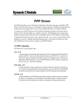
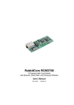
The Wireless Control Application Kit highlights the interface of MaxStream’s 900 MHz XCite™ or 2.4 GHz
XStream™ wireless data modules with one of Rabbit Semiconductor’s single-board computers, the
LP3500. The Wireless Control Application Kit comes with sample programs that illustrate the simple configuration and control of a new or existing Rabbit-based embedded system via a wireless interface using
either the Modbus protocol or a direct point-to-point protocol (PPP) serial connection with a Web browser.
The MaxStream wireless data modules are each mounted on an RS-232/RS-485 Interface Board that
provides the power supply and a DB9 serial interface with flow control. Two wireless data modules and
two RS-232/RS-485 Interface Boards are included in the Application Kit to allow you to attach one assembly to the LP3500 control system, and to use the other assembly with your PC to interface wirelessly with
the LP3500 control system.
LP3500 +
Prototyping Board
S1
S2
S3
S4
GND
VIN
GND VBAT EXT GND
PWM2 PWM1 PWM0
GND
AIN7
AIN6
AIN5
AIN4
AIN3
AIN2
AIN1
AIN0
GND
PROGRAM
PORT
R27
C38
TP2
/RESET
C63
R28
J21
U7
R24
J2
RESET
Q19
C41
U6
R21
J23
R19
D3
C27
R15
R8
R5
R14
C14
C42
C9
D9
RP1
C7
VIN
U2
C5
C23
RP2
C17
C4
D6
D12
JP7
VIN
RP11
GND
RP10
RP12
Q7
Q11
D29
D27
DS1
D23
Q3
C30
RP3
D16
C28
R10
R11
R12
D14
C25
8–15
Q4
R35
D24
IN
R2 +K
R3 GND
R4 VCC
0–7
IN02
J1
DS3
D31
C1
IN03
JP2
C31
JP1
JP4
IN04
DS2
Q9
Q15
D10
RP4
Q21
C68
C69
C49
C18
JP3
IN05
JP6
JP5
R59
IN06
RP8
IN07
RP9
J12
GND
VIN
GND
JP11
IN08
JP12
IN09
R46
IN10
JP8
IN11
GND
IN12
S2
JP9
IN13
R52
R53
J22
C34
JP10
J11
IN14
RN1
Q18
IN15
VIN
GND
VIN
GND
GND
IN00
DS4
J13
D1
J4
GND
J43
R1
J44
PWR
IN01
VIN
J42
J41
J3
3 V VBAT
GND
RxE
TxE
GND
RxC
TxC
GND
RxB
TxB
GND
+ 485 –
GND
+K
OUT9
OUT8
OUT7
OUT6
OUT5
OUT4
OUT3
OUT2
OUT1
OUT0
J5
RS-232 cable
RS-232 cable
Figure 1. Wireless Interface Setup
The sample programs included with the Wireless Control Application Kit serve as a template for a robust
wireless implementation with a serial connection. A Modbus sample program shows how to control the
single-board computer, which is set up as a slave device, from a PC that serves as the Modbus master.
PPP sample programs show how to use the point-to-point protocol directly and via a Web browser.
Possible applications include remote monitoring, proximity sensor readings, wireless I/O control, and data
transmission.
022-0115 Rev. A
1
Table 1 compares the features of the MaxStream 900 MHz XCite™ and 2.4 GHz XStream™ RF modules
used in the Wireless Control Application Kits.
Table 1. Maxstream RF Modules in Wireless Control Application Kit
RF Module
Feature
MaxStream XCite™
MaxStream XStream™
902–928 MHz
2.4000–2.4835 GHz
up to 300 ft (90 m)
up to 600 ft (180 m)
up to 1000 ft (300 m)
up to 3 miles (5 km)
Power Output
4 mW (6 dBm)
50 mW (17 dBm)
RF Data Rate
9.6 Kbps
9.6 Kbps
Interface Data Rate
up to 57.6 Kbps
up to 57.6 Kbps
Receiver Sensitivity
-108 dBm (@ 9600 bps)
-110 dBm (@ 9600 bps)
FHSS (frequency hopping)
FHSS (frequency hopping)
• Peer-to-peer
• Point-to-point
• Point-to-multipoint
•
•
•
•
Filtration Options
• VID (vendor ID number)
• Channels
• Addressing
• VID (vendor ID number)
• Channels
• Addressing
Channel Capacity
7 frequency hopping or
25 single-frequency
7 hop sequences share
25 frequencies
Frequency
Indoor Range
Outdoor Line-of Sight Range
Performance*
Spread-Spectrum Type
Network Topologies Supported
Networking
Addressing
Supply Voltage
65,000 network addresses
per channel
Peer-to-peer
Point-to-point
Point-to-multipoint
Repeater
65,000 network addresses
per channel
2.8–5.5 V DC (regulated)
5 V ± 0.25 V DC (regulated)
Transmit Current
55 mA @ 2.85 V
150 mA
Receive Current
45 mA @ 2.85 V
50 mA
20 µA
26 µA
Power (typical)
Sleep Current
* The maximum range can only be realized with a high-gain antenna. The actual range also depends on
the environment, any structures in the way, network connections, and on whether the Modbus or the
point-to-point protocol is used (the range will be less when using PPP). See Additional Reference
Information for more information on maximizing the range.
MaxStream also offers a 900 MHz XStream™ RF module.
Even though the wireless data modules will operate at baud rates faster than 9600 bps, the 9600 bps baud
rate is used in the sample programs to maximize reliable data transfer over the largest possible distance
using the wire antennas on the wireless data modules included with the Wireless Control Application Kit.
022-0115 Rev. A
2
Application Kit Features
• LP3500 single-board computer with LP3500 Prototyping Board
• Two 900 MHz XCite™ or two 2.4 GHz XStream™ RF modules with two MaxStream RS-232/RS-485
Interface Boards
• Dynamic C CDs for RabbitWeb module, Point-to Point Protocol (PPP) module, and Modbus module
• Complete Dynamic C software CD and supplemental CD with sample programs and reference
information related to the Application Kit
Example Applications
• Low-cost wireless embedded control applications
• Remote monitoring of equipment, devices, locations
• Simple data-logging applications
• Peer-to-peer and point-to-point/multipoint networking control
What Else You Will Need
Dynamic C must be installed on your PC. Insert the Dynamic C CD from the Application Kit in your
PC’s CD-ROM drive. If the installation does not auto-start, run the setup.exe program in the root
directory of the Dynamic C CD. Install the software from the supplemental CD and any Dynamic C
software modules after you install Dynamic C.
Besides what is supplied with the Application Kit, you will need a PC with an available COM or USB port
to program the LP3500 in the Application Kit. If your PC only has a USB port, you will also need an
RS-232/USB converter. Note that not all RS-232/USB converters work with Dynamic C.
022-0115 Rev. A
3
Hardware Setup
The Wireless Control Application Kit Getting Started instructions included with the Application Kit
shows how to set up and program the LP3500 with its Prototyping Board, then interface it wirelessly with
your PC via MaxStream’s 900 MHz XCite™ or 2.4 GHz XStream™ wireless data modules.
The following steps from the Wireless Control Application Kit Getting Started instructions summarize the
setup process once Dynamic C, the Dynamic C modules, and the software from the supplemental CD have
been installed on your PC.
022-0115 Rev. A
4
LP3500 Setup
GND
J8
RELAY
+K
GND 485 +
GND TxB RxB GND TxC RxC GND TxE RxE GND
J4
NC
OUT
3
OUT
4
OUT
2
OUT
0
OUT
1
OUT
6
OUT
5
OUT
7
OUT
8
OUT
9
LP3500 Connections
NO
Q17
K1
Q16
Q13
D32
R55
C55 R44
R56
C61
Q12
C67
U12
R47
Q14
D33
U11
J6
BT1
J9
C59
D13
C43
C29
D11
C66
R45
R39
U8
R41
ery
U3
COM
D34
D30
Y2
R34
R31
D17
R57
C12
Batt
Q6
C51
D28
Q8
C48
RP1
7
D15
C15
C22
D5
R48
C60
C44
Q22
DIS
PLA
Y
R23
C6
R40
U10 RP13
S1
C70
R36
R51
U13
C3
C2
C50
C64
C8
U9
R30
C24
R58
C65
C54
Q20
R16
R18
R17
R7
R9
R26
AIN0 AIN1 AIN2 AIN3
PWM
0
PWM
2
PWM
1
AIN0 AIN1 AIN2 AIN3 AIN4 AIN5 AIN6 AIN7 GND
RESET R50
R49
R32
R54
J5
D22
C40
R22
Y1
C33
R25
C37
J3
R1
C26
R20
RP1
4
D1
R29
IN0
8 IN0
9 IN1
0 IN1
1 IN1
2 IN1
3 IN1
4 IN1
5
D7
C13
R13
R6
R43 Q10
R33
C53
R42 R38
D18 D21
D8
C10
RN1
D26
C36
C20
D4
D2
D25
Q5
J1
IN0
0 IN0
1 IN0
2 IN0
3 IN0
4 IN0
5 IN0
6 IN0
7 GND
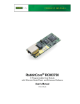
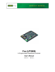
Use the 4-40 screws to attach the metal standoffs to the LP3500 board as
shown.
R37
D19
U1
D20
C16
C19
RN2
VBATGND VIN GND
GND EXT
J2
PROGRAM
PORT
GND
Remove Battery Tab
The backup battery on the LP3500 has a plastic tab to protect the battery
against discharging before the LP3500 is placed into service. The backup battery protects the contents of the SRAM and keeps the real-time clock running
when regular power to the LP3500 is interrupted.
Pull
Plastic
Tab
Attach LP3500 to Prototyping Board
Press the pins from the headers on the bottom side of the
LP3500 firmly into the corresponding header sockets located
at J1, J2, and J4 on the Prototyping Board.
PROGRAM
PORT
TP2
/RESET
C63
R27
C38
R28
U7
Q19
Q18
S2
R19
D3
C27
R15
U6
R8
R5
R14
JP9
C41
C9
C14
C42
R52
R53
R21
C34
RESET
JP10
RP1
D9
C7
U2
JP8
C17
C23
RP2
C5
C4
D6
R46
D12
JP7
D10
JP11
RP4
Q21
C30
RP9
C68
RP10
RP12
Q7
Q11
Q9
Q15
D29
S1
S2
D27
Q3
C25
Q4
R35
D24
S3
R10
R11
R12
D14
S4
GND
C31
VIN
IN
R2 +K
R3 GND
R4 VCC
07
815
JP2
JP1
JP4
D31
D23
RP3
D16
C28
C49
R59
JP6
JP5
C18
JP3
GND VBAT EXT GND
PWM2 PWM1 PWM0
J21
GND
AIN7
AIN6
AIN5
AIN4
AIN3
AIN2
AIN1
AIN0
GND
J23
J22
5
J2
IN1
4
J11
IN1
J2
C69
RP8
RP11
C1
JP12
NOTE: It is important that you line up the header pins on the
LP3500 exactly with the corresponding header sockets J1,
J2, and J4 on the Prototyping Board. The header pins may
become bent or damaged if the pin alignment is offset, and
the LP3500 will not work. Permanent electrical damage
may also result if a misaligned LP3500 is powered up.
R24
LP3500
RN1
VIN
GND
IN1
VIN
3
GND
IN1
D
IN1
1
VIN
GN
2
IN1
0
IN0
9
IN0
D
Prototyping
Board
D
J12
GN
VIN
GN
8
IN0
7
DS2
IN0
J1
DS3
4
2
IN0
1
J13
IN0
D1
0
R1
GN
J43
J44
DS4
IN0
IN0
J4
J42
J41
R
5
3
J4
GND
VIN
PW
IN0
DS1
D
VIN
6
GN
IN0
J1
D
J3
3 V VBAT
GND
RxE
TxE
GND
RxC
TxC
GND
RxB
TxB
GND
+ 485
GND
+K
OUT9
OUT8
OUT7
OUT6
OUT5
OUT4
OUT3
OUT2
OUT1
OUT0
J5
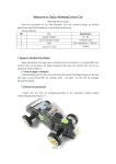
Connect Programming Cable
The programming cable connects the LP3500 to
the PC running Dynamic C to download programs
and to monitor the LP3500 during debugging.
Header J5 is between
the LP3500 and the
Prototyping Board
J5
To
PC COM port
PROGRAM
PORT
Programming
Cable
Colored edge
Connect the 10-pin connector of the programming
cable labeled PROG to header J5 on the LP3500.
Ensure that the colored edge lines up with pin 1
as shown. (Do not use the DIAG connector,
which is used for a normal serial connection.)
Connect the other end of the programming cable
to a COM port on your PC.
Red
shrink wrap
PROG
DIAG
S1
S2
S3
S4
GND
VIN
GND VBAT EXT GND
PWM2 PWM1 PWM0
GND
AIN7
AIN6
AIN5
AIN4
AIN3
AIN2
AIN1
AIN0
GND
PROGRAM
PORT
R27
C38
TP2
/RESET
R28
J21
U7
R24
C63
J2
VIN
S2
U6
D3
C27
R15
R8
R5
R14
C14
C9
RP1
D9
U2
C17
C4
D6
D12
JP7
C30
RP10
RP12
Q7
Q11
Q15
Q9
D29
D27
D23
Q3
R10
R11
R12
D14
C25
Q4
R35
D24
815
IN
R2 +K
R3 GND
R4 VCC
07
J1
IN0
2
DS3
D31
RP3
D16
C28
C31
IN0
3
JP2
JP4
JP1
IN0
4
DS2
R59
C49
JP6
JP5
C18
IN0
5
JP3
VIN
C68
GN
D
C69
RP11
C1
RP4
Q21
RP9
RP8
IN0
6
DS1
D10
JP11
VIN
J12
GN
D
GN
D
IN0
8
JP12
IN0
9
R46
IN1
0
JP8
C23
RP2
C5
IN1
1
GN
D
C42
C7
IN1
2
R52
R53
J23
R19
JP9
C41
IN1
3
Q18
R21
J22
C34
RESET
JP10
J11
IN1
4
IN0
7
GND
GN
D
J43
R1
J44
PW
J4
DS4
J13
IN0
0
D1
J42
J41
R
IN0
1
VIN
X
RN1
Q19
IN1
5
VIN
GND
VIN
GND
J3
NOTE: Be sure to use the programming cable
(Part No. 101-0513) supplied with this Application Kit—the programming cable has red
shrink wrap around the RS-232 converter
section located in the middle of the cable.
Programming cables from other Rabbit Semiconductor kits are not designed to work with
the LP3500.
3 V VBAT
GND
RxE
TxE
GND
RxC
TxC
GND
RxB
TxB
GND
+ 485
GND
+K
OUT9
OUT8
OUT7
OUT6
OUT5
OUT4
OUT3
OUT2
OUT1
OUT0
J5
Do not connect
AC adapter to
VBAT terminal
J5
NOTE: Some PCs now come equipped only with a USB port. It may be possible to use an RS-232/USB converter
(Part No. 540-0070) with the programming cable supplied with the Application Kit. Note that not all RS-232/
USB converters work with Dynamic C.
022-0115 Rev. A
5
Connect Power Supply
Hook up the connector from the 12 V AC adapter to header J5 on the Prototyping Board as shown above.
The orientation of this connector is not important since the VIN (positive) voltage is the middle pin, and
GND is available on both ends of the three-pin header J5.
NOTE: Do not connect the AC adapter to the VBAT terminal on the Prototyping Board. The VBAT terminal supplies the backup battery voltage of 3 V, and the LP3500 may be damaged if subjected to the raw DC voltage
from the AC adapter through the VBAT terminal.
Plug in the AC adapter. If you are using your own power supply, it must provide 3 V to 30 V DC—voltages outside this range could damage the LP3500.
NOTE: A hardware reset may be done by pressing the RESET switch on the LP3500. The LP3500 may also be
reset by unplugging the AC adapter, then plugging it back in. However, when the LP3500 is operating in the
power-save mode, the backup battery will provide sufficient voltage to prevent a reset from happening, in
which case you will have to press the RESET switch on the LP3500. Reset switches are located on both sides
of the LP3500 board.
Run a Sample Program
Once the LP3500 is connected as described, start Dynamic C by double-clicking on the Dynamic C icon or
by double-clicking on dcrab_XXXX.exe in the Dynamic C root directory, where XXXX are versionspecific characters.
If you are using a USB port to connect your computer to the LP3500, choose Options > Project
Options and check “Use USB to Serial Converter” in “Serial Options” on the Communications tab.
Click OK to save the settings.
There are three sample programs available to set up the LP3500 to illustrate a wireless interface via the
MaxStream 900 MHz XCite™ or 2.4 GHz XStream™ wireless data modules.
Type of Interface
Sample Program
Dynamic C Folder
Modbus
MODBUS_SERIAL_SLAVE.C
SAMPLES\Modbus
Point-to-Point Protocol
DIRECT_PPP.C
SAMPLES\WirelessControl
Point-to-Point Protocol
with Web Interface
DIRECT_PPP_HTTP.C
SAMPLES\WirelessControl
RESET switch
JP1
C31
JP4
JP2
C18
JP6
JP5
C49
R59
JP12
JP11
JP7
IN07
C5
C7
IN DR OUT
IN10
IN11
IN13
IN14
D3
IN15
AIN0
AIN1
AIN2
R21
AIN1
VBAT
EXT
R27
420 mA
IN08
IN12
R5
AIN2
R19
C38
C9
R60
C27
AIN3
PROGRAM
PORT
PROGRAM
PORT
C34
R28
RP1
R8
AIN3
TP2
TP2
/RESET
/RESET
U7
U7
GND
IN09
RP2
AIN0
JP8
C41
VDISP
GND
JP3
OUT9
OUT8
OUT7
OUT6
OUT5
OUT4
RESET
RESET
IN02
IN06
R14
R15
IN01
IN05
JP13 D9
C21 C14
JP10
DISP
C63
Q19
PWM2
VBAT
GND EXT GND VIN GND
C52
GND
PWM0
PWM2
022-0115 Rev. A
PWM1
AIN0 AIN1 AIN2 AIN3 AIN4 AIN5 AIN6 AIN7 GND
PROGRAM
PORT
U6
GND
J2
S2
C71
U2
IN00
IN04
C1
C4
C17
JP9
R52
R53
VIN
J5
D22
DPRST
R26
C23
R24
GND
AIN4
A2
+K
GND
VCC
IN03
D6
AIN5
A3
GND
R3
R4
RP3
D10
D12
R46
AIN6
A0
R11
D16
RP4
AIN7
A1
J6
GND
D1
VRAM
PWM0
D0
815 07 IN
R2
R10
R12
RP9
D3
C39
D5
D2
Q18
R54
D14
C42
D4
R58
RP14
R22
R32
C40
AIN0 AIN1 AIN2 AIN3
R25
R29 C37
J3
R1
R20
C25
C30
U5
GND
R51
C70
U13
C64
R17
D1
RESET R50
R49
U4
C28
TP1
Q21
PWM1
D7
Q20
Y1
Q4
RP8
C68
C69
D6
R16
C33
OUT3
COM
DISPLAY
C60
C65
Q3
Q7
RP10
GND
C50 R36 R40 C54
C26
Q11
RP11
RP15
C59
J9
C66
J6
D23
Q9
J4
NC
+K GND 485 + GND TxB RxB GND TxC RxC GND TxE RxE GND
NO
R45
R39
R41
D33
U10 RP13
S1
OUT2
GND
C61
R56 R55
C53
R38
C67
R48
U9
R30
OUT1
GND
D34
R42
Q22
R18
R7
R9
D30
Q5
R13
R6
R47
U11
D24
R35
Q8
BT1
C44
C3
C2
RN1
U12
Q14
D27
D29
RP12
D32
Q12
C55 R44
C43
C13
U8
C24
C10
Q13
Y2
R23
C8
D8
D26
U3
C6
D4
C29
D11
D13
D7
D28
D5
D31
Q15
K1
R33
GND +K
J8 RELAY
Q17
R34
C22
Q16
R43 Q10
Q6
C51
Battery
D17
C12
C20
C48
R57 R31
RP17
D15
C15
IN00 IN01 IN02 IN03 IN04 IN05 IN06 IN07 GND IN08 IN09 IN10 IN11 IN12 IN13 IN14 IN15
D18 D21
GND RxE TxE GND RxC TxC GND RxB TxB GND + 485
CTS RTS
OUT3
OUT2
OUT0
OUT1
OUT6
OUT7
OUT4
OUT5
OUT8
OUT9
D25
C36
C19
RN2
D2
R37
D19
U1
D20
C16
J1
Use the File menu to open the desired sample program, then press function key F9 to compile and
run the program. Remove the programming cable
and reset the LP3500 once the program has compiled and is running. A reset switch is located on
both sides of the LP3500 near the programming
header.
OUT0
The sample programs are listed in order of their increasing complexity.
RESET switch
6
Wireless Data Module Setup
1. Set the DIP switches on both RS-232/RS-485 Interface
Boards to the RS-232 Mode [Switch 1 is ON (up) and
the remaining 5 switches are OFF (down)].
2. Mount each wireless data module to an RS-232/RS-485
Interface Board as shown at right.
3. Use the DB9F to DB9M serial cable to connect one
Interface Board to your PC COM port. You may use
the RS-232/USB converter (Part No. 540-0070) if your
PC does not have a COM port.
ON/OFF LEDs
SWITCH
SERIAL
CONNECTOR
RF Module
O1
N
2 3 4 5 6
Config
button
POWER
INPUT
RS-232/RS-485
Interface
Board
4. Locate and double-click setup_x-ctu.exe in the Dynamic C DCRabbit…\X-CTU software
directory to install the X-CTU application that you will use to set up the wireless data modules.
5. Connect a 9 V AC adapter to the power input on the RS-232/RS-485 Interface Board. Use the ON/OFF
switch on the RS-232/RS-485 Interface Board to turn the Interface Board on— the red LED should light
up.
6. Start X-CTU from the desktop icon and set the “PC Settings” tab to 38400 baud (XCite™ module) or
19200 baud (XStream™ module), NONE flow control, 8 data bits, parity NONE, 1 stop bit. Click
Test/Query, then click OK when you get the report “Communication with modem…OK” that displays
the modem type and firmware. Note the modem type (XC09-038 or X24-019). The settings in this step
apply only when you have a module “fresh out of the box” — otherwise use the settings in Step 8.
7. Click Read on the “Modem Configuration” tab. The modem type identified in the previous step should
display, and you will now set the serial options. Click Write when you have set the serial options.
XC09-038 (XCite™)
• AT Command/Serial Interface Options
CD – D03 Configuration = 2 - low
X24-019 (XStream™)
• Networking
RR – Retries = FF
• Non-AT Settable Parameters/Serial Interfacing Options • Serial Interfacing Options
BD – Interface Data Rate = 3 - 9600
Baud Rate = 3 - 9600
RT – DI2 Configuration = 0 - Disable (Modbus only)
DI2 Configuration = 0 - Disable (Modbus only)
= 2 - RTS flow control (PPP only)
= 1 - RTS flow control (PPP only)
CD – D03 Configuration = 2 - low
NOTE: The D12 configuration varies depending on whether you will be working with the
MODBUS_SERIAL_SLAVE.C or the PPP sample programs. Remember to reconfigure the
wireless data module following Steps 7–8 when changing between these sample programs.
8. Now set the “PC Settings” tab to 9600 baud, NONE flow control (Modbus sample program) or
HARDWARE flow control (other sample programs), 8 data bits, parity NONE, 1 stop bit. Click Test/
Query, then click OK when you get the report “Communication with modem…OK” that displays the
modem type and firmware.
022-0115 Rev. A
7
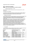
9. Turn the Interface Board OFF, then use the DB9M to
bare wire leads serial cable to connect this Interface
Board to header J41 on the LP3500 Prototyping Board.
Turn the Interface Board back ON.
10. Connect the other Interface Board to your PC COM port
(see Step 3) and repeat Steps 5–8. Leave this Interface
Board connected to your PC.
022-0115 Rev. A
(red) TxC
(brown) RxC
(black) GND
(yellow) RxE
(orange) TxE
LP3500
Prototyping
Board
J3
GND
RxE
12
67
TxE
34
GND
5
J41
After you place the Interface Board connected to the LP3500
some distance away from the PC workstation, you will be
able to try to control the LP3500 wirelessly from the PC
workstation. See Additional Reference Information
for more information on signal loss and maximizing the range.
3 V VBAT
Rx (3)
Tx (2)
GND(5)
/CTS(8)
/RTS(7)
RxC
89
To
RF Modem
TxC
8
Wireless Control Demonstrations
You are now ready to access the LP3500 from your PC through a wireless interface. The specific access
instructions depend on the sample program you loaded on the LP3500. Appendix A documents
the use of the Dynamic C function calls and macros in the sample programs.
MODBUS_SERIAL_SLAVE.C
Start the ModbusMaster application that you installed from the supplemental CD — double-click the
ModbusMaster.exe file in the Dynamic C Modbus folder. Select the LP3500 from the Board pulldown menu, then select your choice of any of DigOut 0 to DigOut 3. The corresponding LEDs on the
LP3500 Prototyping Board will light up once you click “Update Digital Outputs.” If you experience any
problems, check that the COM Port to the right of the board matches the COM port on your PC. If it does
not, you may change it using the COM menu on the menu bar.
You may access the remaining LP3500 I/O by checking the corresponding boxes and clicking the corresponding “Update” button.
The ModbusMaster application performs the functions of a Modbus master in a system that may include
up to five Rabbit-based Modbus slave devices, but is not a complete implementation of a Modbus master.
When the program first starts up, it looks for a definition file (ModbusMaster.ini) within the same
folder. If one is not found, you will be prompted to find one. You may also tell the program to use another
definition file by selecting Read INI from the menu bar. Additional information about the ModbusMaster
application is available in the Dynamic C Modbus/Docs folder.
022-0115 Rev. A
9
DIRECT_PPP.C and DIRECT_PPP_HTTP.C
Before accessing the LP3500 wirelessly, you will have to configure your PC or notebook. If the PC or notebook is connected to a network, it is recommended that you disconnect it from the network. The screen shots
shown here are from Windows XP Professional — the interface is similar for other versions of Windows.
Set Up PC Modem
1. Go to the control panel (Start > Settings > Control Panel) and double-click the Phone and
Modems Options icon.
2. Click the “Modems” tab and press the Add
button. The Add Hardware Wizard will
open.
3. Check the “Don't detect my modem; I will select
it from a list” box and press Next.
4. Click on “Communications cable between two
computers” under Models and press Next.
5. Click the COM port that the PC will be using for
this connection and press Next.
6. Press Finish and then press OK.
022-0115 Rev. A
10
Set Up Network Connection
1. Go to the control panel (Start > Settings > Control Panel) and double-click the Network Connections icon.
2. Click the “New Connection Wizard,” then press Next to bring up the New Connection Wizard.
3. Select “Set up an advanced connection” and press Next.
4. Select “Connect directly to another computer” and press Next.
5. Select “Guest” and press Next.
6. Enter a specific name for the Rabbit-based device (for example, LP3500) and press Next.
7. Select “Communications cable between two computers…” and press Next.
8. Select “Anyone's use” and press Next, then press Finish.
9. When the dialup window pops up, press the Properties button
10. Verify that the COM port selected previously is displayed under the “General” tab and press the
Configure button.
11. Set the “Maximum speed (bps)” to 9600 and check only the “Enable hardware flow control” box, leave
the other settings unchecked, and press OK.
12. Check “Display progress while connecting” under the “Options” tab in the dialup window, and leave
other dialing settings unchecked.
13. Select “Typical (recommended settings)” and “Allow unsecured password” under the “Security” tab in
the dialup window.
14. Press the Settings button under the “Networking” tab, uncheck all the checkboxes, then press OK.
15. Double click “:Internet Protocol (TCP/IP),” then press the Advanced button, uncheck “Use IP header
compression” and uncheck “Use default gateway on remote network” under the “General” tab. Now go
to the “WINS” tab and select “Disable NetBIOS over TCP/IP,”.and press OK.
16. Press OK two more times to close the TCP/IP properties page.
17. Click OK to close the dialup window and save the settings.
The dialup connection should begin and the LP3500 running either sample program will be accessible
wirelessly. The dialup will be repeated a few times before timing out if there is a connection problem. If
you do encounter a connection problem, turn both Interface Boards off, verify that the DB9 connector is
connected securely, then turn the Interface Boards back on.
Double-click the connection you named in Step 6 from the Network Connections window that may be
reached from the control panel (Start > Settings > Control Panel). You may access the LP3500 in the
future from here without having to set up the modem or configure the network parameters again.
What to Expect
If you are running DIRECT_PPP.C on the LP3500, you may ping the LP3500 to demonstrate the PPP
wireless connection. Run the Windows command dialog (Start > Run, then enter cmd) and type the
following ping command:
ping 192.168.66.1
then click Enter. The window will display the results of the ping. Close the window (exit [return})
when you are done.
022-0115 Rev. A
11
If you are running DIRECT_PPP_HTTP.C on the LP3500, you may also ping the LP3500 to demonstrate
the PPP wireless connection following the above instructions. You may also open your Web browser and
enter the following URL to interface wirelessly with the LP3500 via the Web browser.
http://192.168.66.1/
You will get the following display (keep in mind that it may take a minute or two to fully load the various
image components, whose loading status you will be able to watch in the Web browser).
• You may turn the relay ON or OFF by CHECKING or
UNCHECKING Relay One, then clicking on the
CLICK TO UPDATE.
• Try pressing and holding down one of the switches on
the LP3500 Prototyping Board, say the corner switch
S1, then CHECK the Auto Update for the Digital
Inputs. You will see GETTING DATA and SUCCESSFUL UPDATE status messages, and then see a visual
indication in the Web browser that Din one is high.
• UNCHECK any of the D0–D3 Sinking Digital
Outputs, then click on CLICK TO UPDATE. You
will then see the corresponding DS1–DS4 lights light
up on the LP3500 Prototyping Board.
Analog inputs and analog outputs may be handled accordingly.
022-0115 Rev. A
12
Additional Reference Information
The following manuals are available from the documentation installed on your PC when you installed the
Dynamic C CD and the supplemental CD for this application kit.
LP3500 User’s Manual
XCite™ RF Module Product Manual
XStream™ RF Module Product Manual
Check the Rabbit Semiconductor and the MaxStream Web sites for additional information and the latest
versions of supporting documentation.
MaxStream has several documents dealing with RF signal losses, RF installation tips, and selecting a radio
frequency.
Indoor Path Loss
Maximizing Range
900 MHz vs 2.4 GHz
022-0115 Rev. A
13
Appendix A — Software Reference
Sample Programs
MODBUS_SERIAL_SLAVE.C
Let’s examine some of the code in the MODBUS_SERIAL_SLAVE.C sample program. In this sample
program, the LP3500 is the slave device, and the PC is the master.
Macro Definitions
#define
#define
#define
#define
MODBUS_DEBUG_PRINT 0
MODBUS_SLAVE_DEBUG nodebug
USE_MODBUS_CRC
BYTE_TIME 32
Defining the MODBUS_DEBUG_PRINT macro to its default value of 0 means that no messages will be
printed. The MODBUS_SLAVE_DEBUG macro is set to nodebug to compile the MODBUS_SLAVE.LIB
library without any debugging. The USE_MODBUS_CRC macro enables a cyclic redundancy check for the
data. The BYTE_TIME macro sets the maximum number of byte times to wait between received bytes
because the XCite™ wireless data module does not transmit all the bytes in a packet at once.
LP3500 Configuration Macros
#define MY_MODBUS_ADDRESS 3
#define SERIAL_MODE 0
#define MODBUS_PORT C
#define CINBUFSIZE 127
#define COUTBUFSIZE 127
#define MODBUS_BAUD 9600
#define INPUT_ONE LOW
#define OUTPUT_ONE LOW
The MY_MODBUS_ADDRESS macro sets the Modbus address of the LP3500 to 3; Modbus addresses of
1-247 may be used. The SERIAL_MODE macro is set to 0, which causes the serMode() function call to
set up Serial Ports B, C, and E on the LP3500 as regular RS-232 serial ports with no flow control. The
MODBUS_PORT macro assigns Serial Port C as the Modbus serial port. The CINBUFSIZE and
COUTBUFSIZE macros set the buffer sizes of the circular input and output buffers. The MODBUS_BAUD
macro sets the baud rate to 9600 bps. The INPUT_ONE and OUTPUT_ONE macros set whether a logic one
is a high or a low.
LP3500 Operation
The remaining code sets up the analog and digital I/O on the LP3500 so that the Modbus host can then
execute the individual I/O. The MODBUS_Serial_tick() function call checks for command from the
PC that is acting as the Modbus master.
022-0115 Rev. A
14
DIRECT_PPP_HTTP.C
Let’s examine some of the code in the DIRECT_PPP_HTTP.C sample program. In this sample program,
the LP3500 will be the host device, which means that it will wait for the guest device to begin the PPP session. Once the PPP options are negotiated, the host device will use the following network parameters.
HOST_IP "192.168.66.1"
GUEST_IP "192.168.66.2"
The host device will provide the guest device with the following network parameters.
HOST_GATEWAY "192.168.66.1"
HOST_NETMASK "255.255.255.0"
Once the connection is established, the LP3500 will act as an HTTP Web server. The Web server can be
accessed by typing the host’s IP address in the guest PC's Web browser.
First, the program settings used at startup are defined. These macros are used by the parameters in the
function calls, and you may change the macro definitions to suit your needs.
PPP Compile Time Settings
#define TCPCONFIG 0
The TCPCONFIG macro tells Dynamic C to select the TCP/IP configuration from a list of default configurations. When TCPCONFIG 0 is specified, the network parameters are set in the program. Use TCPCONFIG 1 or TCPCONFIG 3 if you are going to access the wireless data module via an Ethernet connection
instead of via a direct serial connection.
#define PPP_BAUD 9600L
This macro sets the PPP baud rate to 9600 bps.
#if((_BOARD_TYPE_ & 0xFF00) == (LP3500 & 0xFF00))
#define LP3500_SBC
#endif
#ifdef LP3500_SBC
#define USE_PPP_SERIAL 0x04
// 0x02 for B, 0x04 for C, 0x08 for D,.....
#define IFS_PPPp IF_PPP2
// IF_PPP0 for A, IF_PPP1 for B, IF_PPP2 for C, .....
#define IFS_PPPn "IF_PPP2" // used for STDIO debugging info
#else // assume RCM3720 and not using Ethernet
#define USE_PPP_SERIAL 0x08
// 0x02 for B, 0x04 for C, 0x08 for D,.....
#define IFS_PPPp IF_PPP3
// IF_PPP0 for A, IF_PPP1 for B, IF_PPP2 for C, .....
#define IFS_PPPn "IF_PPP3" // used for STDIO debugging info
#endif
022-0115 Rev. A
15
This block of code specifies the LP3500, and assigns the serial ports — Serial Port C is used for the PPP
connection. An alternate serial port configuration is provide for the RCM3720 RabbitCore module, which
may also be used without modifying this sample program — the RCM3720 uses Serial Port D for the PPP
connection.
The next macro settings improve the performance of the sample program when using the XCite™ wireless
data module by compensating for its smaller buffer and lack of over-the-air flow control. The macros are
not needed when the XStream™ wireless data module is used.,
#define
#define
#define
#define
#define
#define
ETH_MTU 400
// XCite has a 438 byte buffer
HTTP_MAXBUFFER ETH_MTU-40
TCP_BUF_SIZE (ETH_MTU-40)*2
TCP_MINRTO 250
// min RTO, default 10 ms
RETRAN_STRAT_TIME 25 // check RTO, default 10 ms
TCP_LAZYUPD 250
// packet delays, default 5 ms
Finally, the LP3500 or RCM3720 is identified as the host that will be listening for a guest.
#define DIALUP_SENDEXPECT
"'' &CLIENT @CLIENTSERVER '' @PPP '@'"
Network Settings
#define
#define
#define
#define
HOST_IP "192.168.66.1"
GUEST_IP "192.168.66.2"
HOST_GATEWAY "192.168.66.1"
HOST_NETMASK "255.255.255.0"
These macros set the IP addresses of the LP3500/RCM3720 host and the PC guest, and define the gateway
and netmask for the host.
#define CHK_SIGNAL 20
The CHK_SIGNAL macro specifies a time limit in seconds for the HTTP socket to be idle when PPP is up.
Wireless data modules may lose their signal, but the LP3500 will not recognize that this happened, so the
PC will be pinged when the time limit expires — if there is no response, the PPP connection is terminated
and re-initialized.
#define PING_TIMEOUT 1
The PING_TIMEOUT macro specifies the number of seconds to wait for the ping response.
Network Settings
The LOCAL_VERBOSE macro enables the printing out of error messages in the Dynamic C STDIO window. The colors are also defined here.
022-0115 Rev. A
16
RabbitWeb Macros
#define USE_RABBITWEB 1
#define SSPEC_MAXNAME 32
#define HTTP_MAXSERVERS 1
The USE_RABBITWEB macro is defined to 1 to use the HTTP server enhancements. The
SSPEC_MAXNAME macro defines the maximum length of mime type (default = 20), and the
HTTP_MAXSERVERS macro is set to 1 (one server at a time) to reduce RF traffic.
#memmap xmem
#use "dcrtcp.lib"
#use "http.lib"
The #define of USE_RABBITWEB is followed by a request to map functions not flagged as root into
xmem. The two #use statements allow the application the use of the main TCP/IP libraries (all brought in
by DCRTCP.LIB) and the HTTP server library (which also brings in the resource manager library,
ZSERVER.LIB).
Web Browser Display
The ximport imports the support HTML and javascript pages that are served up by the LP3500 host.
#ximport
#ximport
#ximport
#ximport
#ximport
"pages/index.htm"
"pages/lp3500.htm"
"pages/digital.js"
"pages/analog.js"
"pages/ajax.js"
index_htm
lp3500_htm
digital_js
analog_js
ajax_js
Let’s look at how this is done.
When a Web page is requested by a Web browser, the page is loaded, and any images, scripts, CSS, or
iframes in the page will begin to load automatically as the main page is loaded. Some Web browsers such
as Internet Explorer can only have two simultaneous connections, while other browsers can handle many
more. This can create too much bidirectional traffic for the wireless data modules to handle. Hardware flow
control only works for the wired serial interface to the wireless data modules so they can stop the data
when their buffer is full. There is no such capability for the wireless data flow — the receiving wireless
data module cannot stop the wireless data if its buffer gets full. Most issues here are kept to a minimum by
setting up the wireless data modules for a baud rate of 9600 bps, and the amount of data flowing between
them is further limited by setting the HTTP_MAXSERVERS macro to 1 (one server at a time). We also set
the ETH_MTU macro to 400 bytes because the XCite™ module only has a 438-byte buffer; this ensures
that full packets are sent. The TCP_BUF_SIZE macro is also limited to 2 times the ETH_MTU value
minus 40 (because of extra Ethernet overhead) to prevent windowing. This basically means only one
packet will be sent out and it must be ACKed before the next one is released.
The downloading process is long, and javascript code keeps track of the loading and displays some kind of
status. To do this, the index.htm page uses the onload function to trigger an event when the page is fully
loaded. The event handler or getPage function is then called, and sets an iframe’s source file to
lp3500.htm; the iframe is located in the index.htm page. This causes the browser to fetch the lp3500.htm
022-0115 Rev. A
17
page, then the getPage() function calls the loadStatus function, passing it a “0” for operation and
“lp3500.htm” for file name. The loadStatus function displays that we are getting the lp3500.htm page.
While all this is happing, a script is called every 1000 ms to flash the message “Loading @ <baud> bps”.
When the iframe, which contains the lp3500.htm file, loads, it also triggers its own onload event when it is
fully loaded. The event handler function loadStatus in the index.htm page is called, and passes a “1”
and “lp3500.htm” to indicate that the page has loaded. Another function, getScripts, which is located
in the lp3500.htm page, is called when the onload event occurs. The getScripts function fetches the
digital.js, analog.js, and ajax.jx files one file at a time. Each script file has a call to scriptCb, which is a
function in lp3500.htm. This function lets the lp3500.htm page know that the script has loaded. The
scriptCb function calls the loadStatus function, just like the other pages, to indicate this script has
loaded. The scriptCb function then calls getScript to load the next script, and the process for loading scripts continues until all the scripts are loaded. The number of scripts to load is determined by the
scripts array in the lp3500.htm page. When all files are loaded, the loadStatus function is called with a
“2” parameter to indicate that all files were loaded and to display the elapsed time to load. The pageInit
function in the lp3500.htm page is called, and all RabbitWeb variables are set up. Finally, the
doneLoading function, which is located in the index.htm page stops the flashing “Loading” indicator
and hides the loading status information. The Web browser now displays the loaded iframe (lp3500.htm),
which displays all the I/O controls.
The ajax.js script is used to post and/or get information from the Rabbit-based LP3500 http server. This is
used to create more of a real-time experience when dealing with I/O control and monitoring. AJAX (asynchronous javascripts and XML) provides a more application-type feel for Web pages since it allows the
Web browser to communicate with the http server in the background. This reduces the usual constant
reloading of pages and images when interacting with the web server.
Relays
The LP3500 has a relay, whose control through the RabbitWeb interface is governed by the relaySetup,
relayLabels, relayStatus, and relayOutUpdate function calls. You would simply change the
name or add additional labels to relayLabels to match the relays on your specific board.
int relayLabels;
#web relayLabels select("Relay One")
Digital Inputs
The control of the 16 digital inputs through the RabbitWeb interface is governed by the digInSetup,
digInLabels, digInStatus, and digInUpdate function calls. You would simply change the
name or add additional labels to digInLabels to match the relays on your specific board.
int digInLabels;
#web digInLabels select("Din one", "Din two", "Din three", "Din four",\
"Din five", "Din six", "Din seven", "Din eight", "Din nine",\
"Din ten", "Din eleven", "Din twelve", "Din thirteen",\
"Din fourteen", "Din fifteen", "Din sixteen")
022-0115 Rev. A
18
Digital Outputs
The control of the 10 digital outputs through the RabbitWeb interface is governed by the digOutSetup,
digOutLabels, digOutStatus, and digOutUpdate function calls. You would simply change the
name or add additional labels to digOutLabels to match the relays on your specific board.
int digOutLabels;
#web digOutLabels select("D0 Sinking", "D1 Sinking", "D2 Sinking",\
"D3 Sinking", "D4 Sinking", "D5 Sinking", "D6 Sinking",\
"D7 Sinking", "D8 Sourcing", "D9 Sourcing")
Analog Inputs
The control of the eight analog inputs through the RabbitWeb interface is governed by the anaInSetup,
anaIns, anaInStatus, and anaInUpdate function calls. The anaInSetup function call is used to
assign the Analog Inputs name to the group header and to specify the number of inputs, rows, and column width. Each anaIns label is unique because of the different configurations of each analog channel,
and that is also why the anaInStatus array has a value of 8. You would simply change the name or add
additional labels to anaIns to match the inputs on your specific board.
int anaInSetup; // group header, #of inputs, #of rows, column width
#web anaInSetup select("Analog Inputs","8","2","135px")
int anaIns[8]; // label, unit, min, max
#web anaIns[0] select("Analog In 0", "Volts", "0", "20")
#web anaIns[1] select("Analog In 1", "Volts", "0", "10")
#web anaIns[2] select("Analog In 2", "Volts", "0", "5")
#web anaIns[3] select("Analog In 3", "Volts", "0", "4")
#web anaIns[4] select("Analog In 4", "Volts", "0", "2.5")
#web anaIns[5] select("Analog In 5", "Volts", "0", "2")
#web anaIns[6] select("Analog In 6", "Volts", "0", "1.25")
#web anaIns[7] select("Analog In 7", "Volts", "0", "1")
.
.
void anaInUpdate()
As the analog inputs are read, the anaInUpdate() function call updates their values in the Web
browser.
022-0115 Rev. A
19
for(i=0;i<8;i++)
anaInStatus[i] = anaInVolts(i,i);
The anaInVolts() function call reads each of the eight analog inputs, and in turn converts each raw
reading to a voltage; the first parameter in anaInVolts() is the channel number (0–7), and the second
parameter is the gain code (0–7) as explained in the function help or the LP3500 User’s Manual. The different gain codes for each channel represent different voltage ranges as shown below.
Analog Channel
Voltage Range
0
0–20 V
1
0–10 V
2
0–5 V
3
0–4 V
4
0–2.5 V
5
0–2 V
6
0–1.25 V
7
0–1 V
You may specify a standard gain code for all the channels, you may set up an analog input channel with a
thermistor to measure temperature, or you may configure some of the analog inputs to measure current —
refer to the LP3500 User’s Manual for information on how to do this and the Dynamic C function calls.
The corresponding labels in the sample program might then be as shown below.
int anaIns[8];
#web anaIns[0]
#web anaIns[1]
#web anaIns[2]
#web anaIns[3]
#web anaIns[4]
#web anaIns[5]
#web anaIns[6]
#web anaIns[7]
// label, unit, min, max
select("Analog In 0", "mA", "4", "20")
select("Analog In 1", "mA", "4", "20")
select("Analog In 2", "Volts", "0", "5")
select("Analog In 3", "Volts", "0", "5")
select("Analog In 4", "°C", "0", "20")
select("Analog In 5", "°F", "32", "100")
select("Analog In 6", "Volts", "0", "1")
select("Analog In 7", "Volts", "0", "1")
This reflects the following use of the analog inputs.
• 0—current measurement via anaInmAmps().
• 1—current measurement via anaInmAmps().
• 2—voltage measurement via anaInVolts(2, 2).
• 3—voltage measurement via anaInVolts(3, 2).
• 4—temperature measurement in °C via anaIn(4, SINGLE, 0).
• 5—temperature measurement in °F via anaIn(4, SINGLE, 0).
• 6—voltage measurement via anaInVolts(6, 7).
• 7—voltage measurement via anaInVolts(7, 7).
022-0115 Rev. A
20
Analog Outputs
The control of the three analog outputs through the RabbitWeb interface is governed by the anaOutSetup,
anaOuts, anaOutStatus, and anaOutUpdate function calls. The anaOutSetup function call is
used to assign the Analog Outputs name to the group header and to specify the number of inputs, rows,
and column width. Each anaOuts label is unique to allow for different configurations of each analog
channel, and that is also why the anaOutStatus array has a value of 3. You would simply change the
name or add additional labels to anaOuts to match the outputs on your specific board.
int anaOutSetup; // group header, #of outputs, #of rows, column width
#web anaOutSetup select("Analog Outputs","3","1","150px")
int anaOuts[3]; // label, unit, min, max
#web anaOuts[0] select("PWM 0", "%", "0", "100")
#web anaOuts[1] select("PWM 1", "%", "0", "100")
#web anaOuts[2] select("PWM 2", "%", "0", "100")
As the analog outputs are read, the anaOutUpdate() function call updates their values in the Web
browser. Each of the three PWM analog outputs is set up for a 100% duty cycle in this sample program via
the pwmOut() function call.
022-0115 Rev. A
21
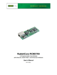
Appendix B — Specifications
(8.36)
(3.3)
1.10
(70)
0.309
(28)
(7.85)
(12.70)
2.75
(6.53)
(4)
0.500
0.15
0.257
1.228
(31.19)
2.132
(54.15)
(56)
(4)
4.00
(21)
(19)
4.40
0.84
0.74
(102)
(2.5)
0.10
(64)
0.329
0.130 dia × 4
2.20
0.15
2.51
(4)
0.16
Complete specifications for the LP3500 and the LP3500 Prototyping Board are available in the LP3500
User’s Manual.
(112)
Figure A-1. RS-232/RS-485 Interface Board Dimensions
(with Wireless Data Module Installed)
NOTE: All measurements are in inches followed by millimeters enclosed in parentheses. All
dimensions have a manufacturing tolerance of ±0.01" (0.25 mm).
Rabbit Semiconductor Inc.
www.rabbit.com
022-0115 Rev. A
22