
1
ACS Color 320 x 240 LCD Display Terminal Quick Start Guide 1 April 2013 Table of Contents Getting Started ............................................................................................................................... 1 What you Need .........................................................................................................................................1 Supplying Power ......................................................................................................................................1 Via SERIAL Connector with ACS Power Injector ...........................................................................1 Via USB DEVICE Connector with USB Cable ................................................................................2 Via ETHERNET Connector with Power Over Ethernet ...................................................................2 Providing Communication........................................................................................................................3 SERIAL Connector ...........................................................................................................................3 DB-9P Signals ............................................................................................................................3 JB1 Configuration Jumpers .......................................................................................................3 RS-232 Connection to PC ..........................................................................................................4 RS-232 LCD (JB1 jumpered as DCE) to PC (DTE) ...........................................................4 RS-232 LCD (JB1 jumpered as DTE) to PC (DTE) ...........................................................5 RS-485 Connection.....................................................................................................................5 USB Connector .................................................................................................................................6 Ethernet Connector ............................................................................................................................6 How the Communication Works ..............................................................................................................7 Terminal Emulators ..................................................................................................................................8 Hyperterminal....................................................................................................................................8 Tera Term ..........................................................................................................................................8 shadeBlue Indigo Terminal Emulator ...............................................................................................8 Initial Power-up ........................................................................................................................................9 Configuring the Display .........................................................................................................................10 Protocols ....................................................................................................................................... 13 ANSI Protocol ........................................................................................................................................13 SOH/ETX Protocols ...............................................................................................................................14 SOH128Mono Mode .......................................................................................................................14 SOH320Mono Mode .......................................................................................................................14 SOH320Color Mode .......................................................................................................................14 ACS Color Basic Programming .............................................................................................................14 Starting with the ANSI Protocol .............................................................................................................15 Communicating with Hyperterminal ...............................................................................................15 Moving to the SOH/ETX Protocol .........................................................................................................18 Drawing Graphics ...........................................................................................................................20 Drawing Text...................................................................................................................................22 Clearing the Display ........................................................................................................................26 Trying ACS Color Basic Programming ..................................................................................................27 Talking to the Color LCD in ACS Basic .........................................................................................28 There Are Rules… ..........................................................................................................................29 Remembering Numbers and Strings ................................................................................................30 Rules for Numeric Data ...........................................................................................................31 Rules for String Data ...............................................................................................................31 Variable Rules ..........................................................................................................................31 Remembering Commands ...............................................................................................................32 Changing your Program ..........................................................................................................34 Controlling the Program Execution .........................................................................................35 Program Rules .........................................................................................................................36 Learning How to Count ...................................................................................................................37 Counting Rules .........................................................................................................................40 Remembering your Programs ..........................................................................................................41 Saving Rules .............................................................................................................................42 Things to do with Numbers .............................................................................................................43 Only Whole Numbers Please ....................................................................................................43 The Size of Numbers .................................................................................................................43 Comparing Numbers ................................................................................................................43 Combining Numbers in Order ..................................................................................................44 Numeric Operator Rules ..........................................................................................................45 Things to do with Strings ................................................................................................................45 Comparing Strings ...................................................................................................................45 Now for Something at Random .......................................................................................................46 It’s a Function!.........................................................................................................................46 Function Rules .........................................................................................................................47 Some Funny Characters...................................................................................................................47 Don’t Get Boxed In ..................................................................................................................48 A Casual Remark......................................................................................................................48 Character Rules .......................................................................................................................49 Don’t Repeat Yourself.....................................................................................................................49 Rules for Subroutines ...............................................................................................................50 Making Changes ..............................................................................................................................51 Rules for Editing ......................................................................................................................52 There’s a System .............................................................................................................................53 System Timers ..........................................................................................................................54 Rules for System Variables .......................................................................................................54 Enough Text – Let’s Draw Something ............................................................................................55 Pixels ........................................................................................................................................55 Clearing The Screen .................................................................................................................56 Drawing Lines ..........................................................................................................................57 Drawing Boxes .........................................................................................................................58 Drawing Circles .......................................................................................................................59 Drawing Ellipses ......................................................................................................................59 Drawing Polygons ....................................................................................................................60 Drawing Text............................................................................................................................61 Drawing Text with Style ...........................................................................................................62 It’s a Matter of Resources .................................................................................................62 It’s a Table of Fonts ..........................................................................................................63 And Now Drawing the Text ..............................................................................................64 Drawing Images .......................................................................................................................65 Rules for Drawing ....................................................................................................................66 Making Things Move ......................................................................................................................66 Warning – Mathematics ...........................................................................................................67 Moving Smarter........................................................................................................................68 Changing Direction .........................................................................................................................70 Rules for Making Things Move ................................................................................................71 Staging an Event..............................................................................................................................71 Rules for Events........................................................................................................................72 Taking Control with the Screen Framework ...................................................................................73 There’s a Table of Screens .......................................................................................................73 Common Schemes Amongst Controls .......................................................................................73 Controlling Screens and Objects ..............................................................................................74 Touch Button Control ...............................................................................................................74 Multiple Objects .......................................................................................................................76 Diving Into the Screen Framework ..........................................................................................77 Rules for the Screen Framework ..............................................................................................77 ACS Color 320 x 240 LCD Display Terminal Quick Start Guide 1 April 2013 Getting Started The ACS Color 320x240 LCD Display Terminal is both easy to use and very powerful. This guide will attempt to get you up and running quickly. What you Need To get started you need the following items: 1. ACS Color 320x240 LCD Display Terminal powered by one of the three Supplying Power options. 2. Host Personal Computer (PC) with an available communications port compatible with one of the three Providing Communication options. 3. Software installed on the PC to provide Terminal Emulation. 4. Windows driver for the PC if a USB connection to the display is used. In the following pages of this guide we will further examine each of these items and how they are used together to get started with the Color LCD. Supplying Power The display requires a source of power to operate. There are three ways to power the display: 1. Using a couple of pins on the SERIAL connector to connect an external power supply. 2. Using a USB connection to supply power. 3. Using the optional Power Over Ethernet (POE) module and an external Ethernet power injection module. WARNING: Do not install the USB_POWER jumper if powering the display through the SERIAL connector or external Ethernet power injection module. High voltage will be injected back through your USB cable to the host computer. Let’s look at each of these options in more detail. Via SERIAL Connector with ACS Power Injector This consists of a back-to-back pair of DB-9 serial connectors with a wall transformer. The Color LCD can be powered through two pins on its SERIAL connector. This injector supplies that power while allowing the other serial connector pins to pass through to your application cabling and hardware. ACS LCD Power Injector -1- ACS Color 320 x 240 LCD Display Terminal Quick Start Guide 1 April 2013 Via USB DEVICE Connector with USB Cable This consists of a USB A to Micro B cable that connects the Color LCD’s DEVICE connector to your PC. The USB_POWER jumper by the USB DEVICE connector must be installed. WARNING: Do not install the USB_POWER jumper if powering the display through the SERIAL connector or external Ethernet power injection module. High voltage will be injected back through your USB cable to the host computer. USB A to Micro B Cable Via ETHERNET Connector with Power Over Ethernet This requires the optional POE module be installed on the Color LCD and an IEEE802.3af Ethernet power injector cabled to the ETHERNET jack on the display. The power injector is placed in series between the host PC or network switch and the display. PWR128RA 19W Power Over Ethernet Injector The connection supports Power Over Ethernet (POE) if the optional POE module is installed on the controller and can be used to power the display with remote power injection. The POE support is IEEE802.af compliant and provides a Class 0 signature. Both DC power on Spares (mode B) and DC power on Data (mode A) operation is supported: ETHERNET Pin # 1 2 3 4 5 6 7 8 POE DC Power on Spares MDI Signal MDIX Signal TX+ TXRX+ PSE+ PSE+ RXPSEPSE- RX+ RXTX+ PSE+ PSE+ TXPSEPSE- -2- POE DC on Data MDI Signal MDIX Signal TX+ PSE+ TX- PSE+ RX+ PSE- RX+ PSE+ RX- PSE+ TX+ PSE- RX- PSE- TX- PSE- ACS Color 320 x 240 LCD Display Terminal Quick Start Guide 1 April 2013 Providing Communication The display can run without any other connections however most applications will require some form of communications between the display and an external device. There are three communication connections: EIA Serial, USB and Ethernet. 1. 2. 3. Using the SERIAL connector to connect to your PC or other communications source. The connection may be either full duplex RS-232 configurable as DCE or DTE with hardware flow control, or half duplex RS485. Using the USB DEVICE connector to connect to your PC or other communications source. The connection emulates a virtual serial port by implementing a Communications Device Class. Using the ETHERNET connector to connect to your PC network or other communications source. The connection provides a 10Base-T/100Base-T with auto negotiation and auto MDI/MDI-X detection and correction. Let’s look at each of these options in more detail: SERIAL Connector The display can function as either a RS-232 DTE (Data Terminal Equipment) or RS-232 DCE (Data Communications Equipment) device. There is a jumper block site on the controller labeled JB1 that can be used to reverse the pins of the signals pairs TxD, RxD and RTS, CTS on the SERIAL connector to accomplish this change. DB-9P Signals Connection to the SERIAL connector requires a female DB-9S mating connector. The following signals appear on the male SERIAL DB-9P connector: DCE Signal PIN SERIAL DB-9P Connector 1 2 3 4 5 6 7 8 9 JB1 as DCE Direction DTE Signal JB1 as DTE Direction RS-485 BRS-232 TxD RS-232 RxD I/O OUT IN RS-485 BRS-232 RxD RS-232 TxD I/O IN OUT GND RS-485 A+ RS-232 CTS RS-232 RTS +12-15VDC PWR I/O IN OUT PWR GND RS-485 A+ RS-232 RTS RS-232 CTS +12-15VDC PWR I/O OUT IN PWR JB1 RS-232 DCE JB1 DTE JB1 RS-485 JB1 Configuration Jumpers JB1 -3- ACS Color 320 x 240 LCD Display Terminal Quick Start Guide 1 April 2013 RS-232 Connection to PC The PC is configured as a DTE device. A one-to-one, female DB-9S to DB-9S cable can be used to connect the PC communication port to the Color LCD SERIAL connector when the Color LCD is configured as DCE. Only four wired connections are required. The RTS connection is for optional flow control of the transmit data to the display to prevent over-flowing the display input buffer at higher baud rates. It requires disabling the RS-485 enable in the display configuration and implementation of flow control on the host device supplying the data to the display. RS-232 LCD (JB1 jumpered as DCE) to PC (DTE) The Color LCD can be connected with a one-to-one cable between the display and host PC when JB1 is configured for DCE: Female Female (To LCD) From Back! (To PC) From Back! 5 6 1 9 5 6 DCE +12 - +15VDC 2 - TxD 3 - RxD 8 - RTS (optional) 5 - GROUND 9 - POWER JB1 GND 1 Power Supply -4- 9 2 - RxD 3 - TxD 8 - CTS (optional) 5 - GROUND ACS Color 320 x 240 LCD Display Terminal Quick Start Guide 1 April 2013 RS-232 LCD (JB1 jumpered as DTE) to PC (DTE) The Color LCD can be connected with a null modem cable (or one-to-one cable with null modem adaptor) between the display and host PC when JB1 is configured for DTE: Female Female (To LCD) From Back! (To LCD) From Back! 1 1 5 9 6 DTE +12 - +15VDC 3 - RxD 2 - TxD 7 - RTS (optional) 5 - GROUND 9 - POWER JB1 GND 6 5 9 2 - RxD 3 - TxD 8 - CTS (optional) 5 - GROUND Power Supply RS-485 Connection The LCD display can be used with RS-485 serial connections. The RS-485 Enable configuration item must be turned on to control when the driver is enabled on the bus: SERIAL Pin # 6 1 5 9 Power Supply LCD SIGNAL GND +12 → +15VDC A+ BGND +12 → +15VDC NOTE: Be sure to connect both the Ground of the PC or Host computer and the Ground of your +12 → +15VDC Power supply together! The RS-485 A+ and B- signals are terminated with a 100 ohm resistor between them. In addition, there is a 10K pull-up resistor on the A+ signal to +3.3v and a 10K pull-down resistor on the B- signal to Ground, to put the received data line in an idle state when there is no connection. -5- ACS Color 320 x 240 LCD Display Terminal Quick Start Guide 1 April 2013 USB Connector The LCD display can be connected as a USB serial communications device. A Micro B USB DEVICE connector is provided and the display can be connected to a PC with a USB A to Micro B cable. DEVICE Pin # Signal Name 1 2 3 4 5 VBUS DD+ ID GND Description USB Power +4.5v Data Data + Identification (nc) Ground A ColorLCD.inf file is available that identifies the Color LCD as a virtual serial port device that implements the Communications Device Class. (A Linux USB CDC configuration file is also available) WARNING: Do not install the USB_POWER jumper if powering the display through the SERIAL connector or external Ethernet power injection module. High voltage will be injected back through your USB cable to the host computer. Connect the USB A to Micro B cable to the Color LCD DEVICE connector. Connect the other end of the cable into a USB port on your PC. DEVICE ColorLCD.inf PC USB ACS Color 320x240 LCD USB A Micro B Cable Windows will indicate that it has found new hardware and will eventually prompt for the location of a driver for the Color LCD. Browse to the location of the ColorLCD.inf file that you have downloaded and select it. Windows should now finish installing the new hardware and it should be ready to use. The COM port identifier that Windows will assign to the Color LCD will depend upon what other communications devices are present in the system and can be determined using the Device Manager. Ethernet Connector The LCD display can be connected as an Ethernet device. A standard RJ-45 connector is provided and it can be connected to a network with a standard Ethernet cable – either straight or crossover, detection and correction is automatic via HP Auto MDI/MDI-X configuration. The network speed can be either 10 or 100 mbps with auto link negotiation. A link activity indicator is provided on the ETHERNET jack. Network PC ETHERNET ACS Color 320x240 LCD Hub / Switch ETHERNET Patch Cable Patch Cable Optional Power Injection Patch Cable The LCD display supports a configurable MAC address and configurable static IP address and IP mask. Serial communication is performed using TCP/IP Raw Sockets with configurable MAC, IP and port addresses. -6- ACS Color 320 x 240 LCD Display Terminal Quick Start Guide 1 April 2013 How the Communication Works The RS-232 SERIAL connection is essentially always connected – even if no physical connection is present. The USB connection is ‘connected’ when the cable is plugged into a host PC where the driver has been installed. The ETHERNET connection is ‘connected’ when the display has been connected to the network and a TCP/IP raw sockets link has been established. Incoming data from each of the three sources are combined asynchronously in parallel into the display protocol that is running. Any output that the display protocol generates is copied to all three outputs synchronously. If a connected output queue fills up, the other outputs are delayed until the full queue has space available - so the slowest connected output limits the output data rate to all of the outputs. Note that some USB hosts like Windows will stop responding to the USB connection if it is connected and there is no application running to receive the incoming data – stopping the output data to all of the outputs. queue USB connection queue Connected SERIAL connection Connected Here’s a diagram: ETHERNET connection queue queue queue queue Display Protocol -7- ACS Color 320 x 240 LCD Display Terminal Quick Start Guide 1 April 2013 Terminal Emulators Communication with the Color LCD display connected to the Host PC requires a software program that can send PC keyboard key presses as characters to the connected display and display characters from the connected display on the PC screen. These programs are collectively, commonly referred to as Terminal Emulators since they emulate the function of older, dumb ANSI terminals that had a dedicated keyboard and display. The display is emulated on the PC screen, typically in a window. The dedicated keyboard is emulated using the PC keyboard. The ANSI character functions are translated in both directions to emulate the terminal operation. Depending upon your LCD application, you may not have a PC in the solution or require communication to one so your software requirement may be different. For the purposes of this Quick Start Guide the use of a PC and terminal emulator program is required. There are several software emulator programs – here are a few that have been tried and are known to work. Hyperterminal Windows 95, 98 and XP shipped with a terminal emulator known as Hyperterminal. Unfortunately this program is no longer supplied with the newer versions of Windows. Here’s a link: http://www.hilgraeve.com/hyperterminaltrial/ Tera Term This is a freeware terminal emulator that is mature and still being developed. Source code is available. The program can be searched for on Google – here’s a link: http://logmett.com/index.php?/download/tera-term-475-freeware.html shadeBlue Indigo Terminal Emulator This is a commercial terminal emulator that is available for purchase online – here’s a link: http://www.shadeblue.com/indigo-features -8- ACS Color 320 x 240 LCD Display Terminal Quick Start Guide 1 April 2013 This emulator is initially more difficult to setup, but is very powerful and has some nice display, command and macro capabilities. Initial Power-up Use one of the previously described power connections to provide power to the Color LCD display. The display should power-up and present some diagnostic and configuration information. Find and press the RESET button on the back of the display. Notice that the display again goes through the powerup sequence. Now we need to configure the display settings for proper operation in your application. When power is applied or the ACS Color LCD 320x240 Display is reset, the controller initializes the display, turns on the backlight, then initializes the non-volatile memory, keypad, serial communications and touch screen. Next, if the touch screen reports that it has a continuous touch, the coordinate of the touch location is used to force the display into one of four startup modes depending upon which quadrant is being touched: Touchscreen Calibration Diagnostics Configuration Settings Program Resource Flash If there is no touch held in any quadrant, the display finishes powering up: -9- ACS Color 320 x 240 LCD Display Terminal Quick Start Guide 1 April 2013 Since we have to configure the display settings we need to enter the configuration mode. Press the RESET button and hold your finger on the lower left quadrant of the touchscreen: Touchscreen Calibration Diagnostics Configuration Settings Program Resource Flash After the diagnostic information the display should enter the configuration mode and display the Configuration Settings screen: Configuring the Display In Configuration Settings mode, the touch keypad is used to adjust or default User Configuration settings. In this mode, the touch keypad is displayed, and the ↑ and ↓ keys are used to scroll between configuration items, one at a time. Let’s try it. Press and release the down arrow once. The screen shows the Protocol: setting. Notice that the fine print legend under the setting and above the keypad indicates that the ← and → keys can also be used to scroll between settings. Try scrolling between the various settings and notice how the settings wrap around after the End Of Config: 0 setting is reached. - 10 - ACS Color 320 x 240 LCD Display Terminal Quick Start Guide 1 April 2013 The legend indicates that you can Edit a setting by pressing the Enter key. Try it – scroll to the Protocol: setting and press the Enter key. The setting highlights to show that it is being edited and the legend changes: Try changing the setting using the arrow keys. Note that the display supports five different Protocols and that the setting value doesn’t wrap around. You can Save the setting at any time by pressing the Enter key again. You can also default the individual setting when editing it by pressing the * key. The Default this Setting question appears: Some settings allow numeric entry of a new value via the number keys. The legend also indicates that we can default all of the settings – probably a good idea so we start with a clean slate. Press and release the * key. The Default ALL Settings question appears: If you press any key other than the # key, the question is answered NO and all the settings will not be defaulted. Press and release the # key to answer yes. The settings are defaulted and the settings screen reverts to the first setting. - 11 - ACS Color 320 x 240 LCD Display Terminal Quick Start Guide 1 April 2013 After defaulting, the display is configured to the (default) settings shown in the following table: # 00 01 02 03 04 05 06 07 08 09 10 11 12 13 14 15 16 17 18 19 20 21 22 23 24 25 26 27 28 29 Setting Firmware Version Protocol Serial Baud Rate Serial Data Bits Serial Stop Bits Serial Parity ANSI Line Wrap ANSI Add LF to CR ANSI Add CR to LF ANSI Local Echo Display Comm Addr Backlight on Recv Backlight on Key Backlight Timeout Backlight On Level Backlight Off Level Send Key Opens Power Up Disp Logo Power Up Disp Setng Auto Clear Disp Sec Auto Clear DispLogo RS485 Enable Key Beep Enable Key Beep Frequency Key Beep Secs/50 TPad in SOH Raw TPad Show Up Left-X TPad Show Up Left-Y TPad Show Lo Right-X TPad Show Lo Right-Y 30 Power Up Quad Detect 31 32 33 34 35 36 37 38 39 40 41 42 43 44 45 TPad Style TPad Scheme PS/2 Enable MAC Address IP Address IP Mask Router IP Address FTP Server Port VNC Server Port HTTP Server Port TCP/IP Raw Port NTP Server NTP Client Port End of Config NV Status Byte Description = version # of firmware 0 = ANSI (default), 1 = SOH128Mono, 2 = SOH320Mono, 3 = SOH320Color, 4 = ACS Basic 1200, 2400, 4800, 9600 (default), 19200, 38400, 57600 7, 8 (default) 1 (default), 2 NONE (default), EVEN, ODD 0 = no wrap (default), 1 = ANSI lines exceeding screen width wrap to next line 0 = CR (default), 1 = incoming CR replaced by CR/LF pair 0 = LF (default), 1 = incoming LF replaced by CR/LF pair 0 = no echo (default), 1 = echo 0 = no address (default), xx = display’s address for SOH/ETX protocol 0 = disabled, 1 = backlight on for time when characters received 0 = disabled, 1 = backlight on for time when switch pressed = number of seconds backlight stays lit (default = 30) 0 = off, 12 = default, 15 = full brightness 0 = off, 5 = default, 15 = full brightness 0 = no (default), 1 = yes 0 = no logo upon reset, 1 = display graphic page 0 (logo) upon reset (default) 0 = no settings shown upon reset, 1 = display settings screen upon reset (default) = number of seconds before display clears (default = 0, off) = number of seconds before logo clears (default = 0, off) 0 = disabled (default), 1= enabled 0 = disabled (default), 1 = enabled 262Hz, 440Hz, 880Hz, 1397Hz (default), 1760Hz, 2093Hz, 3520Hz = duration of key beep in fiftieths of a second (default = 12) = Touch Keypad characters sent outside of SOH/ETX protocol = Touch Keypad Show upper left X coordinate (0 – 319) (default=270) = Touch Keypad Show upper left Y coordinate (0 – 239) (default=0) = Touch Keypad Show upper left x coordinate (0 – 319) (default=319) = Touch Keypad Show upper left x coordinate (0 – 239) (default=48) = 0 no touchscreen quadrant detect upon reset, 1 = detect touchscreen quadrant held upon reset (default) = NONE, QWERTY, NUMERIC, QWERTY TOP, NUMERIC TOP = RED, GREEN, BLUE, GRAY 25%, GRAY 50% 0 = disabled (default), 1 = enabled (requires external adaptor on EXP) = 02:01:23:45:67:89 (default) = 192.168.1.200 (default) = 255.255.255.0 (default) = 192.168.1.1 (default) = 21 (default) = 5900 (default) = 80 (default) = 23 (default) = 64.250.177.145 (default: nist1-atl.ustiming.org) =123 (default) = end of configuration items placeholder = NV status byte (default = 227) Note that if you disable the Power Up Quad Detect you will have to use a hardware jumper to force the display into the Configuration Settings screen on power-up. We’ll start exercising the display using the ANSI protocol which is the default that you’ve now configured. You can exit the configuration mode in two ways: by pressing the physical RESET button or by pressing the Esc (Escape) key on the keypad. Pressing the Esc key asks you to confirm that you wish to reset the display: - 12 - ACS Color 320 x 240 LCD Display Terminal Quick Start Guide 1 April 2013 Using either of the two methods reset the display to exit the Configuration Settings mode. Protocols The ACS Color 320x240 LCD Display Terminal can operate in one of five protocol modes: 1. ANSI – receive and display ASCII characters and some ANSI sequences and send characters entered from either the pop-up keypad or optional PS/2 keyboard. 2. SOH128Mono – emulates the ACS 128x64 LCD by receiving and displaying messages formatted for that display and sends messages corresponding to an on-screen membrane keypad. 3. SOH320Mono – emulates the ACS 320x240 Monochrome LCD by receiving and displaying messages formatted for the display and sends messages or characters entered from either the pop-up keypad or optional PS/2 keyboard. 4. SOH320Color – displays color graphics and images and implements an optional screen/object application interface by receiving and interpreting messages and sends messages or characters entered from either the pop-up keypad, optional PS/2 keyboard or user interaction with screen objects. 5. Acs Basic – provides full display customization by scripting screen graphics, images and user interaction using programs written in an enhanced Beginners All-purpose Symbolic Instruction Code (BASIC) language. The required protocol mode is established using the Configuration Settings screen described above. Let’s look at how these different modes work. ANSI Protocol The ANSI subset protocol allows the display to be used as a limited ANSI terminal with scrolling. In this mode the display interprets the data received over the communications port as ANSI characters and command sequences and shows them on the display. Characters that are entered with the pop-up keypad or the optional attached PS/2 keyboard are sent out over the communications port. The display consists of 20 lines of 45 characters shown using a fixed pitch 6 x 10 pixel font that is drawn in a 7 x 12 pixel matrix. The display supports the concept of a ‘cursor’, which is displayed as a blinking underline, and represents the insertion point on the display where the next printable character that is received will be placed. The ANSI mode supports UTF-8 character coding. Receipt of byte values of printable US ASCII characters (32 decimal / 20 hex through 126 decimal / 7E hex) displays those characters. Extended characters may be displayed using a multi-byte UTF-8 sequence. See the “ACS Color 320x240 LCD Display Terminal User’s Manual , Displayed Characters Appendix” for details. Receipt of these printable characters cause the display to show the character on the screen at the current cursor location, and then move the cursor right to the next position. Escape character sequences may be used to preposition the cursor, clear one or more lines and/or set the coloring for subsequently displayed text. There is a User Configuration setting that will automatically wrap the cursor to the beginning of the next line if required, scrolling the display up if the cursor was on the last line. There are also configuration settings to echo locally typed characters on the display, and perform common end of line character manipulation. - 13 - ACS Color 320 x 240 LCD Display Terminal Quick Start Guide 1 April 2013 A large subset of ANSI command sequences are supported. These allow the cursor to be positioned and the text color to be changed. For a complete list of the supported ANSI sequences see the “ACS Color 320x240 LCD Display Terminal User’s Manual”. SOH/ETX Protocols The SOH/ETX protocols allow full control of the display features and functionality, but require that the host computer properly format sequences of commands using the protocol to control the display, and interpret a formatted response to receive status and data from the display. The SOH/ETX protocol starts each command or response with a single ASCII Start of Header control character = 0116 or CTRL-A, represented herein as <SOH> and ends each command with a single ASCII End of Text control character = 0316 or CTRL-C, represented herein as <ETX>. Command or Response data arguments are sent as ASCII Hex strings one to four characters in length or as printable ASCII characters. Multiple fields may be delineated by embedded ASCII separator control characters depending upon the actual display mode. SOH128Mono Mode This display operating mode emulates most of the functions of the ACS-LCD-128x64 monochrome display. The pixels are drawn doubled in size and there is no support for the hardware keypad overlay – it is emulated on-screen: Please refer to the separate document “ACS-LCD-128x64 User’s Manual” for the serial protocol and commands. SOH320Mono Mode This display operating mode emulates most of the functions of the ACS-LCD-320x240 monochrome display. There is no support for a hardware keypad or input polling: Please refer to the separate document “ACS-LCD-320x240 User’s Manual” for serial protocol and commands. SOH320Color Mode This display operating mode provides an extended command set for operation of the display features. Commands are provided for drawing graphics, displaying bitmaps with transparency, printing UTF-8 text with user-supplied fonts and receiving touchscreen interaction. There is also a higher level screen and object model available to simplify user interaction with buttons and sliders and facilitate multiple screen navigation. ACS Color Basic Programming The protocol setting of ACS Basic is more of an operating mode than a communications protocol. This mode provides full access to all of the display’s features using a superset of the Beginners All-purpose Symbolic Instruction Code – BASIC. The superset provides additional commands and enhancements for manipulating the display. You can develop programs in the ACS Color Basic to implement your application. ACS Color Basic is an integer, microcomputer basic designed for simple control applications. The communications port is used to interactively develop one or more programs that perform the functions of the user’s application. ACS Basic executes programs consisting of one or more statements. Statements consist of an optional line number followed by reserved keyword commands specifying operations for Basic to perform followed by required and / or optional arguments. See the separate document “Color 320x240 LCD Basic Programming User’s Manual” for more information on operating the display in this mode. - 14 - ACS Color 320 x 240 LCD Display Terminal Quick Start Guide 1 April 2013 Starting with the ANSI Protocol Let’s get started using the ANSI Protocol mode. From the earlier section on “Configuring the Display” the Color LCD should be setup to use ANSI Protocol with the baud rate of 9600. If it is not configured for this please return to the earlier section and establish this configuration. We will interact with the display using a terminal emulator and communication connection. If you haven’t already done so, connect the Color LCD to your PC using either the SERIAL or USB connector as shown in the earlier section on “Providing Communication”. Now that the Color LCD is powered, connected and configured we need to start the terminal emulator. We will show how this is done for both Hyperterminal and Tera Term. The use of another terminal emulator would require a similar sequence of steps. Communicating with Hyperterminal The following steps are required to connect to the Color LCD using Hyperterminal. 1. Start Hyperterminal. On Windows XP you can navigate to the program via the Start Button, Accessories, Communications, Hyperterminal: 2. The Hyperterminal program starts and requests information for establishing a new connection. Enter the connection name and choose an icon to represent the connection. You may want to include the communications port and baud rate in the connection name: 3. Hyperterminal requests what communications port you wish to connect to. Select the port that you have connected the Color LCD to with the Connect using drop down: - 15 - ACS Color 320 x 240 LCD Display Terminal Quick Start Guide 4. 1 April 2013 Configure the connection properties using the five drop down boxes to the following: a. b. c. d. e. Bits per second: 9600 Data bits: 8 Parity: None Stop bits: 1 Flow control: None 5. Hyperterminal should now be connected to the Color LCD. Try typing a few words – they won’t show on the Hyperterminal window, but should show on the display. In this screen capture we typed “Now is the time for all good men to come to the aid of their country.” Notice how the typed text wraps around to the next line on the display when it reaches the right-hand edge: 6. Now touch the Color LCD screen in the lower right hand corner. The pop-up keypad should appear at the top of the screen. The location and size of this ‘hotspot’ is configurable in the settings: - 16 - ACS Color 320 x 240 LCD Display Terminal Quick Start Guide 1 April 2013 7. Try typing on the pop-up keypad. The characters that you type should appear in the Hyperterminal window: 8. Try some more communications in both directions. Now let’s clear the Color LCD display by sending an ANSI command sequence. ANSI command sequences start with the ESCape character – the ESCape key is usually located on the upper left of the PC keyboard. The character sequence to clear the display is ESC [ 2 J. These characters must be sent in sequence without any spaces or other characters in-between. Try typing these characters into Hyperterminal and watch the Color LCD screen. If the screen didn’t clear you didn’t type the characters correctly, in the right sequence or without any spaces in-between. The characters that you typed into Hyperterminal with the PC keyboard and into the Color LCD with the pop-up keypad didn’t appear on the on the screen that you typed them into. If you want them to appear, you will have to enable a feature called “Local Echo” on each end – characters that are typed locally are echoed to the screen. In the Color LCD this is controlled by a configuration setting: In Hyperterminal this is configured using the File menu, Properties then ASCII Setup… button: - 17 - ACS Color 320 x 240 LCD Display Terminal Quick Start Guide 1 April 2013 The local echo can cause problems if the system or program that you are communicating with is also echoing the characters that it is receiving – it will appear on the sending device as if each character was typed twice. If this happens you will have to disable local echo on the end of the communications port that is experiencing the double characters. The ANSI Protocol is the easiest way to verify that proper two-way communication is occurring – verifying your wiring and also your settings on both ends of the communications channel. Moving to the SOH/ETX Protocol Now that we have the ACS Color 320x240 LCD Display Terminal connected and communicating we can try another mode using a different protocol. Configure the Color LCD protocol for SOH320Color in the Configuration Settings: When you power-up or reset the display in this mode there is a resource loading status screen shown. This screen clears and the following screen should be momentarily displayed then cleared: - 18 - ACS Color 320 x 240 LCD Display Terminal Quick Start Guide 1 April 2013 This screen should also clear and leave the display blank. At this time you should see the letter R displayed in your terminal emulator program: The R is the display’s Reset status message. The display is now ready to accept commands. In this manual, the <SOH> and <ETX> are used as printed representations of single ASCII control characters: <SOH> Is the printed representation of a single ASCII Start of Heading character; CTRL-A, 01 decimal, 01 hex. This character delineates the start of a command or response in SOH/ETX the protocol modes. This character may be sent from your terminal emulator by holding down the Ctrl key and pressing the A key. <ETX> Is the printed representation of a single ASCII End of Text character; CTRL-C, 03 decimal, 03 hex. This character delineates the end of a command or response in SOH/ETX the protocol modes. This character may be sent from your terminal emulator by holding down the Ctrl key and pressing the C key. The Reset status message is actually bracketed with <SOH> and <ETX> characters, but the terminal emulator shows the non-printing characters as a smiley face ☺ for the <SOH> character and a heart ♥ for the <ETX> character - if the View, Font is set to Terminal. - 19 - ACS Color 320 x 240 LCD Display Terminal Quick Start Guide 1 April 2013 Drawing Graphics Let’s draw a white diagonal line across the display. Looking in the “Color 320x240 LCD Display Terminal User’s Manual, SOH320Color, Draw Commands” section we find the following command template for drawing a line: Draw Line Draws a single color line on the current draw surface between the two coordinates: <SOH> dl XXX YYY xxx yyy CCCC <ETX> Where: Field <SOH> dl XXX YYY xxx yyy CCCC <ETX> Field Name Notes Start of Header Draw Line Line Starting X Coordinate Line Starting Y Coordinate Line Ending X Coordinate Line Ending Y Coordinate Line Color End of Text Ctrl-A (Hex 01) Command/modifier 3-digit ASCII Hex 000-13F 3-digit ASCII Hex 000-0EF 3-digit ASCII Hex 000-13F 3-digit ASCII Hex 000-0EF 4-digit ASCII Hex RGB565 Ctrl-C (Hex 03) At the beginning of the Drawing section the screen coordinates are defined - the X and Y coordinates for drawing start at 0, 0 at the lower left corner of the display and range to 319, 239 at the upper right corner. The hex values of each corner coordinate are shown below each pair: 0, 239 000, 0EF 319, 239 13F, 0EF 0, 0 000, 000 319, 0 13F, 000 We should be able to draw this diagonal line by sending the following characters to the display by typing them into your connected terminal emulator (without the spaces): Ctrl-A dl 000 000 13F 0EF FFFF Ctrl-C The display screen should now look like: If your display doesn’t look like this try typing the command again making sure that you typed all of the letters correctly and that there aren’t any spaces. - 20 - ACS Color 320 x 240 LCD Display Terminal Quick Start Guide 1 April 2013 Now draw a red circle. Looking in the User’s Manual to the Draw Circle command we find the following command template: Draw Circle Draws a single color circle on the current draw surface with a radius at the center coordinates: <SOH> dc XXX YYY RRR CCCC <ETX> Where: Field Field Name <SOH> dc XXX YYY RRR CCCC <ETX> Notes Start of Header Draw Circle Circle Center X Coordinate Circle Center Y Coordinate Circle Radius Circle Color End of Text Ctrl-A (Hex 01) Command/modifier 3-digit ASCII Hex 000-13F 3-digit ASCII Hex 000-0EF 3-digit ASCII Hex 000-13F 4-digit ASCII Hex RGB565 Ctrl-C (Hex 03) To draw this in the center of the screen, the Center X Coordinate should be 320 / 2 = 160 = 0A0 in hex. The Center Y Coordinate should be 240 / 2 = 120 = 078 in hex. Try using a radius of 48 = 030 in hex. The last command parameter is the color. In the Manual Conventions at the beginning of this manual, there is a definition for RGB565: RGB565 Is the printed representation of a 16-bit color comprised of 5 bits of Red, 6 bits of Green and 5 bits of Blue: 15 MSB 14 13 12 11 10 9 8 Red 7 6 5 4 3 2 Green 0 LSB 1 Blue To draw a bright red circle, the leftmost five red bits would all be ones, and the rest would be zero. Translating these RGB565 bit fields to 4-bit hexadecimal fields: 15 MSB 14 1 1 13 12 11 10 9 8 1 1 0 0 0 Red Binary Hex 1 7 6 5 4 3 0 0 0 0 Green F 8 0 2 1 0 LSB 0 0 Blue 0 0 0 So a bright red ASCII HEX RGB565 color would be F800 in hex. We should be able to draw this circle by sending the following characters to the display by typing them into your connected terminal emulator (without the spaces): Ctrl-A dc 0A0 078 030 F800 Ctrl-C The display screen should now look like: Try some of the other Draw commands using different colors to see how they work. - 21 - ACS Color 320 x 240 LCD Display Terminal Quick Start Guide 1 April 2013 Drawing Text Let’s add some text. Looking ahead at the Drawing commands we find the following template for drawing text: Draw Text Draws a UTF-8 text string on the current draw surface using the specified font at the coordinates: <SOH> dt FF XXX YYY textString <ETX> Where: Field Field Name <SOH> dt FF XXX YYY textString <ETX> Notes Start of Header Draw Text Font Number Text X Coordinate Text Y Coordinate Text to be drawn End of Text Ctrl-A (Hex 01) Command/modifier 2-digit ASCII Hex 00-1F 3-digit ASCII Hex 000-13F 3-digit ASCII Hex 000-0EF 8-bit UTF-8 text string Ctrl-C (Hex 03) So let’s print HelloWorld in the center of the screen. We will use font number 00 which defaults to a built-in font that the display uses for diagnostics. Type the following command (without the spaces): Ctrl-A dt 00 0A0 078 HelloWorld Ctrl-C The display screen should now look like: The actual font color will depend upon the configured TPad Scheme – when the display resets the fonts are initialized from the configured, built-in scheme. On your terminal emulator you should see a response from the dt command: dts004F0016 Looking ahead to the Draw Text section of the manual, we can see that this is a response from the draw text command: This command returns a response containing the width and height of the drawn text string to facilitate chaining /aligning subsequent text: <SOH> dts WWWW HHHH <ETX> Where: Field Field Name <SOH> dts WWWW HHHH <ETX> Start of Header Draw Text Size Drawn Text Width Drawn Text Height End of Text Notes Ctrl-A (Hex 01) Response/modifier/parameter 4-digit ASCII Hex 0000-013F 4-digit ASCII Hex 0000-00EF Ctrl-C (Hex 03) - 22 - ACS Color 320 x 240 LCD Display Terminal Quick Start Guide 1 April 2013 This text is being drawn with Font #00. Fonts are a ‘resource’ used by other commands and objects and are controlled by entries in two tables. The first requirement for font usage is an embedded font file that is loaded into the Resource table. There are two or more embedded fonts built-in to the display, and more can be loaded from the on-board serial flash or micro SD card memory. The second requirement for font usage is an entry in the Font table that links the name of the embedded font resource with other font attributes such as color, transparency, spacing and alignment. You can query the display for Font #00’s attributes, and then issue other commands to change them. Looking ahead in this manual to the Query commands you can see that there are commands to Query Fonts and Resources. The command template for a font query command is: Query Font Item The Query Font Item command returns a response showing the requested font item’s current value: <SOH> qti NN <ETX> Where: Field <SOH> qti NN <ETX> Field Name Notes Start of Header Query Font Item Font Number End of Text Ctrl-A (Hex 01) Command/modifier/parameter 2-digit ASCII Hex 00-FF Ctrl-C (Hex 03) To see the attributes for Font #00 type the following Query Font Item command (without the spaces): Ctrl-A qti 00 Ctrl-C On the terminal emulator you should see the response from the qti command: ☺qt0▼AcsDefaultFont.efnt▼16▼0▼8410▼0▼0▼1▼1▼1▼0▲♥ ☺qt0↔♥ Again, there are the bracketing <SOH> (☺) and <ETX> (♥) characters, and, in addition the individual fields of the response are delineated by embedded <US> (▼) characters with the record ending with a <RS> (▲) character. The end of the response is indicated by the trailing qt0 followed by the <GS> (↔) character. The terminal emulator typically doesn’t show these non-printing control characters – some programs can. Here’s a display of the same response using the Indigo Terminal Emulator: <SOH>qt0<US>AcsDefaultFont.efnt<US>16<US>0<US>8410<US>0<US>0<US>1<US>1<US>1<US>0<RS><ETX><CR><LF> <SOH>qt0<GS><ETX><CR><LF> Looking at these fields we can determine the following information about Font #0: Field ☺ = <SOH> qt 0 ▼ = <US> AcsDefaultFont.efnt ▼ = <US> 16 ▼ = <US> 0 ▼ = <US> 8410 ▼ = <US> 0 Field Name Start of Header Query Font Font Number Value Ctrl-A (Hex 01) Response/modifier Font #0 Unit Separator Font File Resource Name Unit Separator Font Height Ctrl-_ (Hex 1F) Name of loaded .EFNT resource Ctrl-_ (Hex 1F) 16 = 22 pixels high Unit Separator Font Background Color Ctrl-_ (Hex 1F) 0 = Black Unit Separator Font Foreground Color Ctrl-_ (Hex 1F) 8410 = Grey Unit Separator Font Spacing-X Ctrl-_ (Hex 1F) 0 = fixed width of the font - 23 - ACS Color 320 x 240 LCD Display Terminal Quick Start Guide Field ▼ = <US> 0 ▼ = <US> 1 ▼ = <US> 1 ▼ = <US> 1 ▼ = <US> 0 ▲ = <RS> ♥ = <ETX> Field Name Unit Separator Font Spacing-Y Unit Separator Font Horizontal Alignment Unit Separator Font Vertical Alignment Unit Separator Background Transparency Unit Separator Foreground Transparency Record Separator End of Text 1 April 2013 Value Ctrl-_ (Hex 1F) 0 = fixed width of the font Ctrl-_ (Hex 1F) 1 = Center Justify Ctrl-_ (Hex 1F) 1 = Center Justify Ctrl-_ (Hex 1F) 1 = Transparent Ctrl-_ (Hex 1F) 0 = Solid Ctrl-^ (Hex 1E) Ctrl-C (Hex 03) This font item record is followed by the group delimiter record indicating the end of this response: <SOH>qt0<GS><ETX><CR><LF> Field <SOH> qt 0 ↔ = <GS> <ETX> Field Name Start of Header Query Font Font Number Value Ctrl-A (Hex 01) Response/modifier Font #0 Group Separator End of Text Ctrl-] (Hex 1D) Ctrl-C (Hex 03) Let’s change font number 00 to be white foreground letters on a red background. To do this you have to change the Font Background Color, the Font Foreground Color and the Background Transparency. Looking ahead in this manual to the Font commands you can see that there are commands to set the Font Colors and Font Attributes. The command template for the command to set the Font Colors is: Font Colors Sets the background and foreground colors used to draw this font table entry: <SOH> fc FF BRGB FRGB <ETX> Where: Field <SOH> fc FF BRGB FRGB <ETX> Field Name Notes Start of Header Font Color Font Table entry number Font Background Color Font Foreground Color End of Text Ctrl-A (Hex 01) Command/modifier 2-digit ASCII Hex 00-1F 4-digit ASCII Hex RGB565 4-digit ASCII Hex RGB565 Ctrl-C (Hex 03) To set the background color to red and the foreground color to white type the following command (without the spaces): Ctrl-A fc 00 F800 FFFF Ctrl-C The command template for the command to set the Font Attributes is: Font Attributes Sets the background and foreground colors used to draw this font table entry: <SOH> fa FF X Y H V B F <ETX> Where: Field <SOH> Field Name Start of Header Notes Ctrl-A (Hex 01) - 24 - ACS Color 320 x 240 LCD Display Terminal Quick Start Guide Field fa FF Field Name Notes Font Attribute Font Table entry number X Font Spacing-X Y Font Spacing-Y H Font Horizontal Alignment V Font Vertical Alignment B Background Transparency F Foreground Transparency <ETX> 1 April 2013 End of Text Command/modifier 2-digit ASCII Hex 00-1F 1-digit ASCII Hex: 0 = fixed width of the font 1→E = pixels between characters F = bounding box character width 1-digit ASCII Hex: 0 = fixed width of the font 1→E = pixels between characters F = bounding box character width 1-digit ASCII Hex: 0 = Left Justify 1 = Center Justify 2 = Right Justify 1-digit ASCII Hex: 0 = Top Justify 1 = Center Justify 2 = Bottom Justify 1-digit ASCII Hex: 0 = Solid 1 = Transparent 1-digit ASCII Hex: 0 = Solid 1 = Transparent Ctrl-C (Hex 03) To set the background transparency to solid (and keep the other font attributes the same type the following command (without the spaces): Ctrl-A fa 00 0 0 1 1 0 0 Ctrl-C You can verify that the colors and attributes have been set by using the Query Font Item command again: Ctrl-A qti 00 Ctrl-C Now the response should be: ☺qt0▼AcsDefaultFont.efnt▼16▼F800▼FFFF▼0▼0▼1▼1▼0▼0▲♥ ☺qt0↔♥ Looking at these fields we can verify that we changed Font #0: Field qt 0 ▼ = <US> AcsDefaultFont.efnt ▼ = <US> 16 ▼ = <US> F800 ▼ = <US> FFFF ▼ = <US> 0 ▼ = <US> 0 Field Name Query Font Font Number Value Response/modifier Font #00 Unit Separator Font File Resource Name Unit Separator Font Height Ctrl-_ (Hex 1F) Name of loaded .EFNT resource Ctrl-_ (Hex 1F) 0016 = 22 pixels high Unit Separator Font Background Color Ctrl-_ (Hex 1F) F800 = Red Unit Separator Font Foreground Color Ctrl-_ (Hex 1F) FFFF = White Unit Separator Font Spacing-X Unit Separator Font Spacing-Y Ctrl-_ (Hex 1F) 0 = fixed width of the font Ctrl-_ (Hex 1F) 0 = fixed width of the font - 25 - ACS Color 320 x 240 LCD Display Terminal Quick Start Guide Field Field Name Unit Separator Font Horizontal Alignment Unit Separator Font Vertical Alignment Unit Separator Background Transparency Unit Separator Foreground Transparency Record Separator End of Text ▼ = <US> 1 ▼ = <US> 1 ▼ = <US> 0 ▼ = <US> 0 ▲ = <RS> ♥ = <ETX> 1 April 2013 Value Ctrl-_ (Hex 1F) 1 = Center Justify Ctrl-_ (Hex 1F) 1 = Center Justify Ctrl-_ (Hex 1F) 0 = Solid Ctrl-_ (Hex 1F) 0 = Solid Ctrl-^ (Hex 1E) Ctrl-C (Hex 03) Issue the same Draw Text command by typing the following command (without the spaces): Ctrl-A dt 00 0A0 078 HelloWorld Ctrl-C The display screen should now look like: Try changing the other Font Attributes to see the results. Clearing the Display So, how do we clear the display? Again looking ahead to the Draw commands we don’t see a Clear sub-command, but there is a Fill. The display is cleared by filling the screen with the desired color. Here’s the command description: Draw Fill Flat Fills an area of the current draw surface defined by a lower-left coordinate, width and height with a constant color: <SOH> dff XXX YYY WWW HHH CCCC <ETX> Where: Field Field Name Notes <SOH> dff XXX YYY WWW HHH CCCC <ETX> Start of Header Draw Fill Flat Lower-left Fill X Coordinate Lower-left Fill Y Coordinate Fill Width Fill Height Fill Color End of Text Ctrl-A (Hex 01) Command/modifier/parameter 3-digit ASCII Hex 000-13F 3-digit ASCII Hex 000-0EF 3-digit ASCII Hex 000-140 3-digit ASCII Hex 000-0F0 4-digit ASCII Hex RGB565 Ctrl-C (Hex 03) To clear the screen to black, issue a Draw Fill Flat command that covers the entire screen with the color black (0000): Ctrl-A dff 000 000 140 0F0 0000 Ctrl-C The screen should now be blank (black). - 26 - ACS Color 320 x 240 LCD Display Terminal Quick Start Guide 1 April 2013 Trying ACS Color Basic Programming Now that we have the ACS Color 320x240 LCD Display Terminal connected and communicating we can try another mode using the fifth protocol – ACS Basic. First configure Hyperterminal to not echo local characters since Basic will be echoing any characters that it receives. Then configure the Color LCD protocol for ACS Basic in the Configuration Settings: Now when the Color LCD is reset notice the ACS Basic sign on message and Ready prompt: Notice that the same sign on message and Ready prompt appear on Hyperterminal: In this mode the Color LCD understands a language called ACS Basic. ACS Basic is a customized form of the “Beginners All-purpose Symbolic Instruction Code”. The original Basic was developed back in 1964 to provide computer access to people who didn’t usually program. This version provides additional commands and features that make it useful to program an interactive display. - 27 - ACS Color 320 x 240 LCD Display Terminal Quick Start Guide 1 April 2013 Talking to the Color LCD in ACS Basic Try pressing the  key on your PC’s keyboard. The Color LCD display indicates that it is awaiting instruction by responding with Ready. Ready is the display’s prompt – it is waiting for a command from you. Try typing the following as your first command – type this exactly as it is shown: PRINT “Hello World” When you reach the end of the line, review it for mistakes. Did you put the quotation marks where they were shown? If you made a mistake, simply press the ø key and the last character that you typed will disappear. You can backspace over the entire line if necessary. Your PC (and display screen) should look like this: Ready PRINT "Hello World!" Now press the  key and see what happens. Your screen should now look like this: Ready PRINT "Hello World!" Hello World! Ready The Color LCD display executed the command that you entered by printing the message that you had in quotes. Now let’s try another command: PRINT “2 + 2”  The Color LCD executes your command by printing: 2 + 2 Ready If you expected to see the number four, then try removing the quotation marks: PRINT 2 + 2  The Color LCD executes your command by printing: 4 Ready The Color LCD sees everything that you type as either Strings or Numbers. If it’s in quotes, it’s a String and the display sees it exactly as it was typed. If it’s not in quotes it’s a Number. The Color LCD will figure it out like a numerical problem. It it’s not in quotes the display can interpret it by adding, subtracting, multiplying or dividing it. Let’s try a multiplication problem: PRINT 1589 * 2  PRINT 1589 * 2 3178 Ready The Color LCD uses an asterisk as a multiplication sign rather than an X since the X character is alphabetical and can be part of a name as we will see later. - 28 - ACS Color 320 x 240 LCD Display Terminal Quick Start Guide 1 April 2013 There Are Rules… The Color LCD is very literal. If it doesn’t understand what you have typed it will produce an error message to let you know. Try typing this line deliberately misspelling the word PRINT: PRIINT “HI”  The Color LCD prints: PRIINT "HI" Syntax error - no equals Ready The display doesn’t understand what you have typed. The “Syntax error” message indicates that the command “PRIINT” is not one that it knows how to do. It also tries to provide additional information to help you figure out the error, “- no equals”, but in this case it is confused and this doesn’t help. Try leaving off the last quotation mark. Type: PRINT “HI  The Color LCD prints: PRINT "HI Mis-matched quotes error Ready The Color LCD will also give you error messages when it does understand what you have typed, but the command will result in incorrect operation. For instance, try typing: PRINT 5 / 0  The display prints: PRINT 5 / 0 Divide by zero error Ready This error message indicates that you’re asking it to divide by zero – which is not possible. - 29 - ACS Color 320 x 240 LCD Display Terminal Quick Start Guide 1 April 2013 Remembering Numbers and Strings One of the features of the Color LCD is the ability to remember things you ask it to. For example, to make the display remember the number 13, type this: A = 13  Now try the other PRINT commands that you did before. To see if the display still remembers what A is equal to, type: PRINT A  And the display should print: PRINT A 13 Ready The Color LCD remembers that the placeholder A has the number value of 13 until you turn it off or change it. Type: A = 17  A = 17 Ready PRINT A 17 Ready So what happened? When you first set A equal to 13 the display created a named memory location to hold that value. You can refer to that location by the name A to retrieve the current value of the memory location as with the PRINT A command above. You can also modify the value of the named memory location by setting it to a new value. You can use combinations of letters and numbers to name these memory locations – the only requirement is that the name must not start with a number. Try typing these commands: B = 15  C2 = 20  LongName = 25  Now ask the Color LCD to retrieve all of these numbers by name. Type: PRINT A, B, C2, LongName  And the display should show: PRINT A, B, C2, LongName 17 15 20 25 Ready To get the Color LCD to remember strings of letters or numbers, put a dollar sign at the end of the name. Type: A$ = "Remember"  B$ = "this for me"  And then ask the display to display them: PRINT A$, B$ Remember this for me Ready In computer terminology these named memory locations are referred to as variables. The Color LCD keeps track of these variables and their current values for you. You can ask it for a list of what variables it is currently remembering by typing the command: VARS  - 30 - ACS Color 320 x 240 LCD Display Terminal Quick Start Guide 1 April 2013 And the display will show the variables that we’ve used so far along with their current contents: VARS A B C2 LongName A$ B$ Ready R/W R/W R/W R/W R/W R/W Int Int Int Int Str$ Str$ = = = = = = 17 15 20 25 "Remember " "this for me" The R/W indicates that the variable can be both Read from and Written to. Later on we will see how to make variables Read Only. The Int indicates that the display understands this variable to be for holding Numbers, Str$ indicates that the variable holds strings. And of course the Color LCD is picky about what is stored in the two types of variables. Try typing these lines: D = “6”  D$ = 6  With both of these lines the display responds with an error message: D = "6" Wrong expression type error - can't assign string to numeric var Ready D$ = 6 Wrong expression type error - can't assign number to string var Ready In computer terminology, setting variables to values is referred to as assigning a value to a variable. There are four fundamental rules for variable value assignment: Rules for Numeric Data 1. 2. Numbers not in quotes are Numeric Data Numeric Data can only be assigned to variables named without a trailing dollar sign Rules for String Data 1. 2. Any data in quotes is String Data String Data may only be assigned to variable name with a trailing dollar sign Variable Rules 1. 2. 3. 4. 5. 6. You may use multiple characters from the upper case letters A-Z, the lower-case letters a-z, the numbers 09 and the ‘_’ underscore character for variable names. The first character of the name must be a letter, not a number or underscore. Variable names are case-sensitive: Aname is not the same as aNAME. Variables whose names end with a dollar sign can only hold String Data, otherwise they can only hold Numeric Data. The list of current variables can be shown with the VARS command. Short, concise variable names take less memory and work faster. - 31 - ACS Color 320 x 240 LCD Display Terminal Quick Start Guide 1 April 2013 Remembering Commands First we need to erase everything that the Color LCD has remembered so far. Type: NEW  Now type this command line: Be sure and type the number 10 first: 10 PRINT “Hello from the Color LCD”  Notice that this time, when you pressed  nothing appeared to have happened. Not that you can immediately see. What you did was to type your first program. Type: RUN  The display now runs your program. You can type RUN again and again. You can also type run – ACS Basic’s commands are not case-sensitive, just variable names: 10 PRINT "Hello from the Color LCD" RUN Hello from the Color LCD Ready run Hello from the Color LCD Ready So the number at the beginning of the line tells Basic to store the line instead of executing it. Let’s add another line to the program. The number at the beginning of the line is the “line number”. Type: 20 print “What’s your name?”  Now let’s ask the Color LCD to show us the entire program. Type: LIST  The display LISTs your entire program so far – notice how the lower-case print command was capitalized and how the lines are stored and shown in line number order: LIST 10 PRINT "Hello from the Color LCD" 20 PRINT "What's your name?" Ready Now run the program: Type: RUN  The Color LCD prints: RUN Hello from the Color LCD What's your name? Ready Try answering the question by typing your name and pressing  . . . there’s that Syntax error again – the display didn’t understand what you meant when you typed in your name: RUN Hello from the Color LCD What's your name? Ready Steve Syntax error - no equals Ready In fact you have to instruct the Color LCD to accept your answer by giving it a command, INPUT, to do so. Add this line to the program: 30 INPUT Name$  The INPUT command tells the display to stop and wait for you to type something which it will assign to the variable Name$. Add one more line to the program to show the Name that was entered: - 32 - ACS Color 320 x 240 LCD Display Terminal Quick Start Guide 1 April 2013 40 PRINT “Hi, “, Name$  Now LIST the program. It should look like: LIST 10 PRINT 20 PRINT 30 INPUT 40 PRINT Ready "Hello from the Color LCD" "What's your name?" Name$ "Hi,", Name$ Now let’s RUN the program: RUN Hello from the Color LCD What's your name? ? Steve Hi, Steve Ready You can run the program many times, answering the question with different names – the display doesn’t care what name you use. After each RUN the variable Name$ holds the last name you entered. You can make your program run over and over without having to type the RUN command each time. Add this line to the program: 50 GOTO 10  Now RUN the program. It runs over and over without stopping. The GOTO command told the Color LCD to go back up to line 10. Your program will repeat over and over because every time it executes line 50 it jumps back to line 10. In computer terminology this is referred to as a loop. The only way to stop this endless loop is to press the Ÿ key twice in a row followed by the  key. This is known as ESCaping the program and the display tells you that you escaped: Hello from the Color LCD What's your name? ? ŸŸ  ESC at line 30 Ready In this program the  key was required following the double Ÿ key because the Color LCD was waiting for the  key at the INPUT command. If the display is not waiting for INPUT the double Ÿ key is sufficient to ESCape the program. - 33 - ACS Color 320 x 240 LCD Display Terminal Quick Start Guide 1 April 2013 Changing your Program So how can you modify your program without typing NEW and starting over each time? To replace an existing program line simply type the new line using the same line number at the beginning of the line you want to replace. Type: 50 GOTO 40  Your program should now look like: 50 GOTO 40 LIST 10 PRINT "Hello from the Color LCD" 20 PRINT "What's your name?" 30 INPUT Name$ 40 PRINT "Hi,", Name$ 50 GOTO 40 Ready This program change modifies the loop to not ask the question over and over. Instead the program now just keeps repeatedly PRINTing the Name$ that you INPUT the first time. Press the Ÿ key twice in a row to ESCape the program when you’ve seen enough. Notice that you don’t need to press the  key to ESCape this time because the display is not waiting for INPUT: RUN Hello from the Color LCD What's your name? ? Steve Hi, Steve Hi, Steve Hi, Steve Hi, Steve Hi, Steve Hi, Steve Hi, Steve Hi, Steve Hi, Steve Hi, Steve Ÿ Ÿ ESC at line 40 Ready To remove a line from your program simply type the line number followed by the  key. This erases that line from your program. Type: 50  This removes line 50 from your program: 50 LIST 10 PRINT 20 PRINT 30 INPUT 40 PRINT Ready "Hello from the Color LCD" "What's your name?" Name$ "Hi,", Name$ Put line 50 back into your program. Type: 50 GOTO 40  Now let’s change the way that the PRINT shows your name. Replace line 40 in your program by typing it again, but add a semicolon at the end: 40 PRINT “Hi,“, Name$;  - 34 - ACS Color 320 x 240 LCD Display Terminal Quick Start Guide 1 April 2013 Now RUN the program. Notice how the trailing semicolon crams everything together? 40 PRINT "Hi, ", Name$, LIST 10 PRINT "Hello from the Color LCD" 20 PRINT "What's your name?" 30 INPUT Name$ 40 PRINT "Hi, ", Name$, 50 GOTO 40 Ready run Hello from the Color LCD What's your name? ? Steve Hi, SteveHi, SteveHi, SteveHi, SteveHi, SteveHi, SteveHi, SteveHi, SteveHi, SteveHi, SteveHi, SteveHi, SteveHi, SteveHi, SteveHi, SteveHi, SteveHi, SteveHi, SteveHi, SteveHi, SteveHi, SteveHi, SteveHi, SteveHi, SteveHi, SteveHi, SteveHi, SteveHi, SteveHi, SteveHi, SteveHi, SteveHi, SteveHi, SteveHi, SteveHi, SteveHi, SteveHi, SteveHi, SteveHi, SteveHi, SteveHi, SteveHi, SteveHi, SteveHi, SteveHi, SteveHi, SteveHi, SteveHi, SteveHi, SteveHi, SteveHi, SteveHi, Ste ESC at line 40 Ready SteveHi, SteveHi, SteveHi, SteveHi, SteveHi, SteveHi, SteveHi, SteveHi, SteveHi, SteveHi, Controlling the Program Execution You’ve seen that a program can be RUN from lowest line number to highest. The program can also loop using the GOTO command. And a running program may be ESCaped to stop. Another way to control the execution of a program is to GOTO only if a certain condition is met. Let’s change our program so that it stops if we enter a blank name. Modify line 40 to remove the trailing comma by typing: 40 PRINT “Hi,“, Name$  Now replace line 50 with a new IF / THEN command. The new IF / THEN command evaluates a condition, and, IF the condition is True, THEN it executes the commands after the THEN. Otherwise execution continues with the following program line. Type: 50 IF Name$ <> “” THEN GOTO 20  In this example the IF condition that is being evaluated is: Name$ < > “”. Name$ is the variable that receives your INPUT up until the  key. The < > (less than, greater than) stands for “not equal to”, and the “” is an empty string – a string with no characters in it. So your program should now look like: LIST 10 PRINT "Hello from the Color LCD" 20 PRINT "What's your name?" 30 INPUT Name$ 40 PRINT "Hi,", Name$ 50 IF Name$ <> "" THEN GOTO 20 Ready Run the program. Try entering your name the first time your program asks for it, then the next time simply press the  key. Notice how the program loops back to line 20 when your name was INPUT otherwise the program stops: RUN Hello from the Color LCD What's your name? ? Steve  Hi, Steve What's your name? ?  Hi, Ready - 35 - ACS Color 320 x 240 LCD Display Terminal Quick Start Guide 1 April 2013 When you press the  key in response to the INPUT command without typing any characters first, the INPUT variable receives an empty string otherwise the variable holds any characters that were typed in before the  key. You can think of line 50 as reading: IF variable Name$ not equal to empty string THEN GOTO line 20. And that is exactly what the program is doing. However there is an error. In computer terminology this is called a program bug. Notice how the program still prints Hi, before it stops when nothing is ENTERed. This is because the program executes line 40 before it checks for Name$ being empty. In order to fix this ‘bug’ we have to check for the stop condition before we PRINT the Name$. Replace line 40 with the new IF / THEN check. Type: 40 IF Name$ = “” THEN STOP  And then replace line 50 with the PRINT command. Type: 50 PRINT “Hi,“, Name$  The program should now look like: LIST 10 PRINT "Hello from the Color LCD" 20 PRINT "What's your name?" 30 INPUT Name$ 40 IF Name$ = "" THEN STOP 50 PRINT "Hi,", Name$ 60 GOTO 20 Ready RUN Hello from the Color LCD What's your name? ? Steve Hi, Steve What's your name? ? STOP in line 40 Ready The new STOP command does exactly that – it stops the program from running and shows you what line the program stopped on. You can also use the END command which stops without the message. Try it by changing line 40. Program Rules 1. 2. 3. 4. 5. 6. 7. 8. 9. 10. 11. 12. A program consists of one or more command lines that begin with a line number. Commands are not case-sensitive but are converted by Basic. Variables are case-sensitive. Program lines and variables may be cleared from memory by the NEW command. Program lines are kept in ascending numeric order by the display. A program is RUN to execute the lines in numeric order starting with the lowest numbered line. Program lines may be shown with the LIST command. The execution order of program lines may be changed by the GOTO command. A program which is executing repeatedly in a loop may be ESCaped by pressing the Ÿ key twice in a row. A program line may be replaced by typing a new program line with the same line number. A program line may be deleted by typing the line number only followed by Â. Program line execution may be conditioned by the IF / THEN command. Program execution may be stopped with the STOP or END commands. - 36 - ACS Color 320 x 240 LCD Display Terminal Quick Start Guide 1 April 2013 Learning How to Count Most programs require the ability to count – lines, key presses, characters, loops or other things. With the commands that you already know you can write a program that counts. First we need to learn a fundamental concept. In order to add to a variable you can use it on each side of the assignment equals sign. For example, type: A = 1  PRINT A  A = A + 1  PRINT A  With assignment A = A + 1, the current value of A has one added to it then it becomes the new value of A. The value to add doesn’t have to be 1, it can also be the value of another variable. You can read this statement as “Variable A equals the value of Variable A plus 1”. So in order to count from 1 to 10 we can write the following short program. Start fresh by typing: NEW  First we set the value of the counter, A, equal to 1. Type: 10 A = 1  Then we print it. Type: 20 PRINT A  Then we add one to it. Type: 30 A = A + 1  Then we check to see if A is less than or equal to 10… and, if so, we loop back to print the new value. Otherwise we’re done counting: 40 IF A <= 10 THEN GOTO 20  Now list the program. It should look like: LIST 10 A = 1 20 PRINT A 30 A = A + 1 40 IF A <= 10 THEN GOTO 20 Ready Now RUN it: RUN 1 2 3 4 5 6 7 8 9 10 Ready Simple – right? However, ACS Basic provides another way to count with fewer commands that’s a little easier to read. Start fresh by typing NEW  again. Now we will work with a new two command combination: FOR / NEXT. The FOR command replaces two commands: line 10 - the setting of the initial count value, and line 40 – the check for the end count value. The NEXT command replaces two commands: line 30 – the advance of the count value, and the GOTO portion of line 40 – the counting loop. Let’s see how this works. - 37 - ACS Color 320 x 240 LCD Display Terminal Quick Start Guide 1 April 2013 First the FOR command. This command determines the count variable, its initial value and the ending value. Type: 10 FOR A = 1 TO 10  Now as before we PRINT the count value. Type: 20 PRINT A  And finally the NEXT command. This command advances the count value and executes the loop if more counting is necessary. This is referred to as closing the loop. Type: 30 NEXT A  Now list the program. It should look like: LIST 10 FOR A = 1 TO 10 20 PRINT A 30 NEXT A Ready Now RUN it: RUN 1 2 3 4 5 6 7 8 9 10 Ready This program is one line shorter, but does the same thing. It is also easier to read and comprehend. Try changing the initial and ending value to see the results. Great! But what if we want to count by two – how do we do that. It seems like the A = A + 1 is implied. The Basic language designers thought of that and have provided another keyword that can be added to the end of the FOR command to specify the value to be added each time around the loop – STEP. The STEP keyword goes at the end of the FOR command – after the ending value. Let’s replace line 10 with this new FOR command that has a STEP 2 on the end: 10 FOR A = 1 TO 10 STEP 2  Your program should now look like: LIST 10 FOR A = 1 TO 10 STEP 2 20 PRINT A 30 NEXT A Ready Now RUN it: RUN 1 3 5 7 9 Ready The initial value, ending value and optional STEP value don’t have to be numbers – they can also be numeric variables. And the STEP value can be negative to. Let’s replace line 10 again to try this. Type: 10 FOR A = 10 TO 1 STEP -1  - 38 - ACS Color 320 x 240 LCD Display Terminal Quick Start Guide 1 April 2013 Your program should now look like: LIST 10 FOR A = 10 TO 1 STEP -1 20 PRINT A 30 NEXT A Ready And when you RUN it: RUN 10 9 8 7 6 5 4 3 2 1 Ready There’s a few more important things to know about FOR / NEXT. First, you shouldn’t try to GOTO into the middle of a FOR / NEXT loop. When the Color LCD encounters the NEXT command without having seen the matching FOR first it gets confused and gives you an error. Here’s an example of that error – we add a line at the beginning of the program to GOTO line 20 which is inside the FOR / NEXT loop: LIST 5 GOTO 20 10 FOR A = 10 TO 1 STEP -1 20 PRINT A 30 NEXT A Ready RUN 0 Nesting error in line 30 - NEXT without preceding FOR The second thing to remember is that if you nest FOR / NEXT loops – one inside of another, you must close the inner loop before closing the outer loop. Here’s the right way to nest loops: LIST 10 FOR X = 1 TO 3 20 FOR Y = 3 TO 1 STEP -1 30 PRINT "X = ",X, " Y = ",Y 40 NEXT Y 50 NEXT X Ready RUN X = 1 Y = 3 X = 1 Y = 2 X = 1 Y = 1 X = 2 Y = 3 X = 2 Y = 2 X = 2 Y = 1 X = 3 Y = 3 X = 3 Y = 2 X = 3 Y = 1 Ready And here’s the wrong way to nest loops: LIST 10 FOR X = 1 TO 3 20 FOR Y = 3 TO 1 STEP -1 30 PRINT "X = ",X, " Y = ",Y 40 NEXT X 50 NEXT Y Ready RUN X = 1 Y = 3 Nesting error in line 40 - NEXT var doesn't match FOR var Ready The third thing to remember is that you shouldn’t try to GOTO out of a FOR / NEXT loop. While you won’t receive an immediate error, the cleanup performed by the NEXT statement isn’t performed and if you do it enough times - 39 - ACS Color 320 x 240 LCD Display Terminal Quick Start Guide 1 April 2013 you will get an error when there isn’t sufficient memory left for the display to remember more FOR / NEXT commands. Exiting a FOR / NEXT loop early is a fairly common programming requirement however so ACS Basic provides a system form of GOTO to jump out – EXITFOR. To try it, modify our existing program. First remove line 5 by typing: 5  And then add line 40 to indicate that we’re done counting and provide a target line for the EXITFOR command: 40 PRINT “Done”  And finally add a condition check for exiting the FOR / NEXT loop – let’s say when the count variable is equal to 5 we want to leave the loop. Type: 15 IF A = 5 THEN EXITFOR 40  Your program should now look like: LIST 10 FOR A = 10 TO 1 STEP -1 15 IF A = 5 THEN EXITFOR 40 20 PRINT A 30 NEXT A 40 PRINT "Done" Ready And when you RUN it: RUN 10 9 8 7 6 Done Ready Counting Rules 1. A variable can appear on both sides of the assignment equal sign. The variable on the right hand side refers to its existing value and the left hand side variable will receive the new value. 2. You can implement a count sequence by assigning an initial value to a variable, advancing it by adding or subtracting to it then checking if it is at the ending value and looping back if it is not. 3. Basic provides a FOR / NEXT command with an optional STEP clause to simplify counting. 4. Nested FOR / NEXT loops must be closed from the inside out – inside loops first. 5. You can’t jump into the middle of a FOR / NEXT loop – an error will result on the NEXT command. 6. You should only jump out of a FOR / NEXT loop using the system EXITFOR command. - 40 - ACS Color 320 x 240 LCD Display Terminal Quick Start Guide 1 April 2013 Remembering your Programs The Color LCD wouldn’t be very useful if you always had to type in your programs every time you turned it on. The longer your programs are the more of a problem this would become. The Color LCD has a slot for a micro SD memory card. You can SAVE your programs by name on the card and LOAD or RUN them later by referring to the same name. Think of the micro SD card as a file drawer that holds many files. You can create a new file and put it in the drawer, or retrieve an existing file from the drawer. You can’t retrieve a file that hasn’t been created first. The Color LCD will keep a directory listing of what files are in the drawer (on the micro SD card). Let’s try it. Put a fresh card into the slot and ask for a directory of files. Type: DIR  On a fresh card you should see the following: DIR ---------------------------------------------0 files 0 directories Ready The display is showing you that there are currently no files on the card. Now type in one of your earlier programs – remember to start with NEW Â. Let’s start with the simple FOR / NEXT program: NEW 10 FOR A = 1 TO 10 20 PRINT A 30 NEXT A You can RUN it to verify that it works as before. Now let’s SAVE it in a file. Let’s call it FORNEXT. Type: SAVE FORNEXT  Did it save it? Let’s ask for a directory again: DIR FORNEXT.BAS 43 A 02-26-2012 04:57:02 PM ---------------------------------------------1 files 0 directories Ready There it is. The display is telling us that it’s 43 characters long, it was created on 2-26-2012 at 4:57PM and that there is one file on the card. What’s the .BAS on the end of the file name? There can be many types of files in the drawer (on the card) and this is Basic’s way of telling us that this file is a Basic program. Great! Now let’s try to get it back. First clear out the program and variables with NEW. Try a LIST and VARS to see that there’s actually nothing in memory: NEW Ready LIST Ready VARS Ready Now let’s retrieve it. Type: LOAD FORNEXT  And then LIST it: LOAD FORNEXT Ready LIST 10 FOR A = 1 TO 10 20 PRINT A 30 NEXT A Ready And there it is. You can RUN it to verify that it still works. - 41 - ACS Color 320 x 240 LCD Display Terminal Quick Start Guide 1 April 2013 Modify it to count backwards by changing line 10 and adding the STEP keyword: 10 FOR A = 10 TO 1 STEP -1  You can LIST and RUN it. Then let’s SAVE this as FORNEXTSTEP. Type: SAVE FORNEXTSTEP  Now let’s ask for a directory again: DIR FORNEXT.BAS 43 FORNEXTSTEP.BAS 51 ---------------------------------------------2 0 Ready A A 02-26-2012 04:57:02 PM 02-26-2012 05:12:56 PM files directories Both programs (files) are there. ACS Basic provides a shortcut for loading and running a program file – just type RUN followed by the file name. Basic will do the NEW, LOAD and RUN all in a single step: RUN FORNEXT 1 2 3 4 5 6 7 8 9 10 Ready RUN FORNEXTSTEP 10 9 8 7 6 5 4 3 2 1 Ready Saving Rules 1. Programs can be filed onto a micro SD card installed in the Color LCD. 2. A directory of what files are on the card can be obtained by the DIR command. 3. Programs are saved to the card with the SAVE command. 4. Programs are retrieved from the card with the LOAD command. 5. Programs may be retrieved and executed with the RUN command. 6. ACS Basic remembers the last program file name used with LOAD, RUN or SAVE so a modified program can be saved into the same file using a SAVE command without a name. - 42 - ACS Color 320 x 240 LCD Display Terminal Quick Start Guide 1 April 2013 Things to do with Numbers So far we’ve seen that the Color LCD can add and multiply numbers – using numbers directly or numbers stored in variables. The display can also subtract and divide numbers. In computer terminology these actions are referred to as operators. Let’s try a few: PRINT 4 - 2 2 Ready PRINT 9 / 3 3 Ready Here’s a new operator that you probably haven’t heard of or used before – remainder of division. In computer terminology this is referred to as a modulo operation. The first number is divided by the second number and the remainder is returned. So if two numbers divide evenly, the modulo is zero – no remainder: PRINT 10 % 5 0 Ready However if the two numbers don’t divide evenly, the modulo operator returns the remainder after the division that would be performed. So if we divide 5 by 4, the remainder or modulo would be 1: PRINT 5 % 4 1 Ready Operators usually go between two numbers or numeric variables. However there are some operators that go in front of a single number or variable. In computer terminology these are referred to as unary operators. There are a couple of these, but the most common is a leading minus sign – referred to as negate: A = 10 Ready PRINT -A -10 Ready This is just a shorthand way of telling the Color LCD to subtract the number from zero. Only Whole Numbers Please Now let’s try dividing two numbers that don’t divide evenly – say 10 divided by 3: PRINT 10 / 3 3 Ready What happened? Shouldn’t 10 divided by 3 equal 3 and 1/3? It should but this shows a limitation of ACS Basic – it only knows how to work with whole numbers – not decimals or fractions. So when it divides 10 by 3 it returns the whole number part and discards the fractional part. In computer terminology this is referred to as integer arithmetic. While this can be a limitation for solving some problems most applications of the Color LCD can be performed only using integers – and there are some workarounds that we’ll examine later. Remember, the modulo operator can return the remainder of the same division. The Size of Numbers So if ACS Basic can only work with whole numbers, how big can they be? What’s the limit? This Basic works with what programmers refer to as short integers – they are 16 computer bits wide. A computer bit can only be on or off – when you have 16 of them across, with each one able to be on or off, the biggest number that they can represent is 65535 which is the number 2 raised to the 16 th power (65536) less one reserved for the zero = 65535. Actually the computer in the Color LCD reserves 1 bit for a plus or minus indicator – a sign bit. So there are really only 15 bits available for the actual number. So the maximum positive number is +32767 and the maximum negative number is -32768. Comparing Numbers There are also operators for comparing two numbers. Numbers can be checked to see if they’re the same or not or if one is larger or smaller than another. In computer terminology these checks are called comparison operators – two - 43 - ACS Color 320 x 240 LCD Display Terminal Quick Start Guide 1 April 2013 numbers are compared with each other. The results of a comparison are either true or false. In ACS Basic, a true comparison results in a 1 and a false comparison results in a zero. To check for equality (two numbers being the same) we use the equal operator – which is the equals sign: PRINT 1 = 0 0 Ready PRINT 2 = 2 1 Ready So how do you test if two numbers are not equal? ACS Basic uses a less than followed immediately by a greater than (no space in-between) as the not equal operator. Notice how this check gives the opposite result of the equal check. PRINT 1 <> 0 1 Ready PRINT 2 <> 2 0 Ready Of course we can also check for numbers being less than, less than or equal, greater than and greater than or equal: PRINT 0 Ready PRINT 1 Ready PRINT 0 Ready PRINT 1 Ready 2 < 2 2 <= 2 4 > 4 4 >= 4 Combining Numbers in Order You don’t have to only do a single operation on numbers at a time. You can combine them into a series of operations to achieve the result you want. In computer terminology this is referred to as an expression. Usually, when you perform a bunch of operations on numbers you do them in a left-to-right order. So if you want to add two numbers, and now double the result you might write: PRINT 2 + 3 * 2 8 Ready You would expect the result to be 2 plus 3 equals 5 times 2 equals 10 – right? How did the Color LCD come up with the number 8? It turns out that in Basic, like most computer languages there is an order in which numeric operations are performed. In computer terminology this is referred to as operator precedence or operator priority. If there wasn’t an defined order then you could get different results each time or perhaps different results between different machines. Negation is performed first, then Multiplication, Division and Modulo, then Addition and Subtraction, then Comparisons are performed last. So the display does the 3 times 2 first, then it adds the 2 which gives 8 instead of 10. What if you really want these operations done in the order that you wrote them down? Well it turns out that you can specify the order by grouping operations together using parenthesis. The Color LCD Basic will execute operations inside parenthesis first, then use that result to perform the next operation in the expression. So to get the result that you wanted above, you could write: PRINT (2 + 3) * 2 10 Ready - 44 - ACS Color 320 x 240 LCD Display Terminal Quick Start Guide 1 April 2013 So when in doubt, or when you really want things done in a certain order, use parenthesis to group operations together. The display will evaluate things from the inside out starting with the most nested set of parenthesis first. Numeric Operator Rules 1. Numbers can be added, subtracted, multiplied, divided, remaindered, negated and compared. 2. Multiple operations can be performed sequentially to form a numeric expression. 3. Multiple operations are performed in a priority fashion from first to last: negation, multiplication and division, addition and subtraction, then comparison. 4. Multiple operations with the same priority are performed left to right. 5. Parenthesis can be used to change the order in which numeric expressions are evaluated. Things to do with Strings There are also operations that can be performed on strings. The most common of these are to combine two separate strings into a new single string by ‘adding’ one string onto the end of another. In computer terminology this is referred to as concatenation – the two strings are concatenated together: PRINT "HELP" + "ME" HELPME Ready Part1$ = "Help" Ready Part2$ = "Me" Ready PRINT Part1$ + " " + Part2$ Help Me Ready Comparing Strings Like numbers you can also compare strings. The two strings are compared, a character at a time to determine if they are the same, less than or greater than each other: PRINT 0 Ready PRINT 1 Ready PRINT 0 Ready PRINT 1 Ready "ONE" = "TWO" "ONE" <> "TWO" "ONE" > "TWO" "ONE" < "TWO" - 45 - ACS Color 320 x 240 LCD Display Terminal Quick Start Guide 1 April 2013 Now for Something at Random By now we’ve learned a few different commands that the Color LCD Basic understands. Let’s try something new. Type this line: 10 PRINT RND(10)  And now RUN it. The display printed a random number between 0 and 9. RUN it a few more times: 10 PRINT RND(10) Ready RUN 8 Ready RUN 7 Ready RUN 5 Ready RUN 1 Ready Now make the program loop back to run continuously. Add line 20 to the program and RUN it. You will have to ESCape the program to stop it: 20 GOTO 10 LIST 10 PRINT RND(10) 20 GOTO 10 Ready RUN 7 8 6 9 8 0 0 7 4 9 9 ESC at line 10 Ready What if we want to have random number from 0 to 100? Changed line 10 to this and RUN it: 10 PRINT “”, RND(100); LIST 10 PRINT “”, RND(100); 20 GOTO 10 Ready RUN 59 51 31 73 82 62 38 92 78 58 71 84 28 94 46 43 2 59 26 80 32 41 44 43 12 31 30 84 18 58 4 80 11 3 39 14 60 0 42 33 95 95 9 56 80 91 16 54 7 86 37 12 25 45 37 82 67 29 95 26 9 23 62 74 57 80 6 16 83 68 64 39 22 45 37 81 50 56 93 56 58 4 70 17 0 28 81 99 61 22 36 74 27 9 19 12 9 38 32 87 41 18 35 12 28 40 60 22 38 83 23 58 23 17 30 75 95 11 46 12 67 7 26 52 7 39 1 70 67 69 39 53 0 63 28 25 94 39 27 94 7 20 25 52 94 88 45 38 99 25 92 72 25 45 15 67 5 48 19 66 71 20 51 74 12 36 89 24 6 4 60 80 29 55 46 48 30 29 14 86 80 7 84 50 26 74 53 78 44 3 9 19 94 8 24 42 99 92 58 31 73 27 46 23 55 49 29 82 27 49 97 54 75 64 88 62 49 8 65 52 73 36 9 74 60 35 62 37 46 63 1 88 46 50 64 5 96 21 43 68 19 77 51 37 57 25 55 65 21 84 89 77 72 72 76 68 84 49 6 93 82 42 93 57 75 39 87 94 70 94 61 97 32 45 79 39 92 24 49 20 8 7 39 7 16 78 2 16 15 90 53 19 10 11 76 82 99 70 27 83 97 94 29 34 78 35 69 22 70 26 29 84 90 97 11 16 3 42 83 77 52 86 39 48 91 80 37 ESC at line 10 Ready 56 85 70 86 65 75 71 10 97 It’s a Function! So the function of RND( ) is to produce random numbers. It takes a numeric value between the parentheses, computes a random number based upon the number that it’s given and then takes on the value of that random number. It’s kind of like a command and kind of like a variable at the same time. In computer terminology these - 46 - ACS Color 320 x 240 LCD Display Terminal Quick Start Guide 1 April 2013 combination command / variables are referred to as functions. Because they are part of the Basic language and don’t have to be rewritten each time you want to use them they are referred to as built-in functions. Since functions act like a variable you can use them wherever you would read a variable – like in a PRINT command, an IF / THEN conditional check or in an expression. The difference between a function and a variable is that you can’t assign a value to a function – you can only pass arguments to it and then use the value that it assumes as a result. In computer terminology this is referred to as calling a function that takes an argument and returns a value. It’s like a variable, but you don’t assign values to it – instead you pass it one or more arguments between the parenthesis and it acts like a variable whose value changes based upon the arguments. There are other functions that are very useful when writing Basic programs. Some take no arguments but return a value – either numeric or string. Some take one or more numeric arguments and return a numeric value. Some take string arguments and return a numeric value. Some take both string and numeric arguments and return a value. So how do you know what type of value a built-in function will return? Just like a Basic variable – it’s all in the name. If a built-in function returns a string value, the function name ends with a dollar sign – otherwise it returns a numeric value. This makes sense because functions can be used in place of variables. Function Rules 1. Functions behave like read-only variables that can supply different values or behavior in your programs depending upon what they are pre-defined to do and what arguments that they may require to do it. 2. When calling a function, the function name must be immediately followed by the opening parenthesis surrounding the function’s arguments. 3. The type of a function is identified by the name, just like a variable. Some Funny Characters Your communications device – whether it is a PC or PS/2 keyboard or even the pop-up touch keypad has a limited set of characters. Your program may require some special characters or symbols be displayed – like a degree symbol after a temperature for example. The Color LCD can display these characters that don’t appear on the keyboard, but it takes a couple tricks. The first trick is the understanding that each displayed character is actually based upon a number. Back in the 60’s a standards committee got together and hashed out a definition of what number represents what character. It started with the old telegraphic codes for characters and evolved to support the newly designed teleprinters. In computer terminology this is called A.S.C.I.I. – which is the abbreviation for American Standard Code for Information Interchange. It defines 128 characters and control codes, each of which can be uniquely represented by a seven bit number. There’s a chart of these numbers and their representative characters at http://www.asciitable.com . Now when we want to show a certain character we just have to the single 7-bit number to be sent to the display. This means we need a function that takes in a decimal number and converts it to a single number representing the string character based upon this ASCII standard. ACS Basic has just such a function built-in. The CHR$( ) function takes a decimal number argument and returns a single character string where the character is the ASCII character of the decimal number. This character can then be sent to the display by PRINTing it. Let’s try it: PRINT CHR$(65) A Ready PRINT CHR$(48) 0 Ready So how do we display characters that aren’t in the ASCII standard? It turns out that there is another standard call Unicode which defines how to combine multiple non-ASCII codes into a single extended character. Remember that ASCII only defines 7-bit codes, 0 – 127. Since computers work with 8-bit codes, 0 – 255, that leaves codes 128 – 255 available. However the Unicode designers didn’t want to limit themselves to just 128 more characters – multiple languages required many more. So they came up with an expandable scheme using multiple prefix characters that can be combined and decoded to represent many more extended characters. - 47 - ACS Color 320 x 240 LCD Display Terminal Quick Start Guide 1 April 2013 Sound complicated – and it can be – if you have to do the encoding and decoding. However the Color LCD only provides display support for what is known as the DOS – United States character set. There is a table of these supported characters at the end of this manual. To display them you just have to send the multiple character sequence underneath the character. The definition of what values represent what extended characters was also defined starting in the 60’s and is loosely known as the ANSI code standard. ANSI stands for American National Standards Institute. So let’s try showing that degree character. From the table, it looks like the two codes are 194 and 176 – remember to separate the two function calls with a semicolon – if you use a comma instead it won’t work because a space character (32) will get inserted between them: print chr$(194);chr$(176) ° Ready And there it is. You can try some others from the table – some take two codes and some three. Using Basic PRINT commands to display characters is referred to as ANSI operation. Don’t Get Boxed In If you look at the Extended Characters table at the end of the manual, there are some that can be used for line drawing. Let’s try and draw a simple box. We need the four corners, the lines across the top and bottom and the lines on the side. Try typing this short program in – don’t forget to NEW first: 10000 10005 10010 10015 10020 10025 10030 10035 10040 10045 10050 10055 10060 10065 10070 10075 REM Draw a box using ANSI characters PRINT CHR$(226); CHR$(148); CHR$(140); FOR I=1 TO 10 PRINT CHR$(226); CHR$(148); CHR$(128); NEXT I PRINT CHR$(226); CHR$(148); CHR$(144) PRINT CHR$(226); CHR$(148); CHR$(130); FOR I = 1 TO 10 PRINT " "; NEXT I PRINT CHR$(226); CHR$(148); CHR$(130) PRINT CHR$(226); CHR$(148); CHR$(148); FOR I=1 TO 10 PRINT CHR$(226); CHR$(148); CHR$(128); NEXT I PRINT CHR$(226); CHR$(148); CHR$(152) And now RUN it: run ┌──────────┐ │ │ └──────────┘ Ready save ansibox Ready If it works as shown then you can save it for later. Now you’re probably asking yourself a couple of questions: First, what is the REM command on the first line? We’re glad you asked. Second, why are the line numbers so large? We’ll get to that shortly. A Casual Remark The REM command allows you to put notes (REMarks) into your programs. The REM command actually does nothing - when ACS Basic ‘sees’ the REM command it skips over the rest of the line. In computer terminology the use of the REM command is referred to as commenting your code. It serves a couple of purposes – reminding yourself about what you were trying to do with this code, and documenting what you hope that it does as an aid for others. While it doesn’t seem important now with these tiny programs, it will become increasingly important when the programs get larger and you have many more of them to keep track of. It’s considered good practice. The large line numbers allow us to come back later and put some lower-numbered lines before these. In this example they’re going to let us save some typing. - 48 - ACS Color 320 x 240 LCD Display Terminal Quick Start Guide 1 April 2013 Character Rules 1. 2. 3. 4. 5. Characters are actually a displayed version of a single number. The first 128 characters (numbers 0 – 127) have been agreed upon and are referred to as the ASCII character set. Refer to http://www.asciitable.com There is a built-in function, CHR$( ) that can convert a numeric argument into a character. Additional extended characters may be displayed using multiple character prefix codes. Using Basic PRINT commands on the display is known as ANSI operation. Don’t Repeat Yourself Suppose that you want to draw two boxes, one above the other. You could type the same thing in again, duplicating all of these lines. Your programs would tend to get quite large – and, you might run out of line numbers. What you have now is a box-drawing routine. Suppose you could just call this routine whenever you wanted to draw a box. Good News! You can. There is a routine calling command in most computer languages – including ACS Basic. In computer terminology these common routines are referred to as subroutines. So how do you get to this part of your program from somewhere else? And how do you get back? The new command pair is GOSUB / RETURN. And they are a pair – you can’t have one without the other. The computer terminology is calling into a subroutine and returning from a subroutine – call in and return back right after where you called from. Let’s add some additional lines to the program: 10 print “Here’s a box:” 20 gosub 10000 30 print “And here’s another:” 40 gosub 10000 50 end And don’t forget the last line that will turn the box drawing lines into a subroutine: 10080 return Your program should now look like this: list 10 PRINT "Here's a box:" 20 GOSUB 10000 30 PRINT "and here's another:" 40 GOSUB 10000 50 END 10000 REM Draw a box using ANSI characters 10005 PRINT CHR$(226); CHR$(148); CHR$(140); 10010 FOR I=1 TO 10 10015 PRINT CHR$(226); CHR$(148); CHR$(128); 10020 NEXT I 10025 PRINT CHR$(226); CHR$(148); CHR$(144) 10030 PRINT CHR$(226); CHR$(148); CHR$(130); 10035 FOR I = 1 TO 10 10040 PRINT " "; 10045 NEXT I 10050 PRINT CHR$(226); CHR$(148); CHR$(130) 10055 PRINT CHR$(226); CHR$(148); CHR$(148); 10060 FOR I=1 TO 10 10065 PRINT CHR$(226); CHR$(148); CHR$(128); 10070 NEXT I 10075 PRINT CHR$(226); CHR$(148); CHR$(152) 10080 RETURN Ready - 49 - ACS Color 320 x 240 LCD Display Terminal Quick Start Guide 1 April 2013 And when you run it: run Here's a box: ┌──────────┐ │ │ └──────────┘ and here's another: ┌──────────┐ │ │ └──────────┘ Ready If you change the GOSUB to a GOTO you will get an error when your program executes the RETURN command – it doesn’t know the way back that is remembered by the GOSUB. Subroutines are used to replace common or duplicate code. If you look at our program there’s another common piece of code that could be made into a subroutine – the PRINTing of the Unicode prefix for the box drawing extended characters: PRINT CHR$(225); CHR$(148); Let’s make this repetitive code into a separate subroutine – it could go above or below, we’ll put it below: 10100 REM Print the Unicode prefix characters 10105 PRINT CHR$(226); CHR$(148); 10110 RETURN list 10 PRINT "Here's a box:" 20 GOSUB 10000 30 PRINT "and here's another:" 40 GOSUB 10000 50 END 10000 REM Draw a box using ANSI characters 10005 PRINT CHR$(226); CHR$(148); CHR$(140); 10010 FOR I=1 TO 10 10015 PRINT CHR$(226); CHR$(148); CHR$(128); 10020 NEXT I 10025 PRINT CHR$(226); CHR$(148); CHR$(144) 10030 PRINT CHR$(226); CHR$(148); CHR$(130); 10035 FOR I = 1 TO 10 10040 PRINT " "; 10045 NEXT I 10050 PRINT CHR$(226); CHR$(148); CHR$(130) 10055 PRINT CHR$(226); CHR$(148); CHR$(148); 10060 FOR I=1 TO 10 10065 PRINT CHR$(226); CHR$(148); CHR$(128); 10070 NEXT I 10075 PRINT CHR$(226); CHR$(148); CHR$(152) 10080 RETURN 10100 REM Print the Unicode prefix characters 10105 PRINT CHR$(226); CHR$(148); 10110 RETURN Ready And now we have to change lines 10005, 10015, 10025, 10030, 10050 10055, 10065 and 10075. You could type these lines over, but as we’ll see soon, ACS Basic has a shortcut – the EDIT command. Rules for Subroutines 1. Any block of code can be turned into a subroutine by adding a RETURN command as the last line and then calling the code using the GOSUB command. 2. GOSUB commands must be paired with RETURN commands – you can’t GOTO in or out of a subroutine. 3. Subroutines can be nested – code inside a subroutine can call another subroutine. - 50 - ACS Color 320 x 240 LCD Display Terminal Quick Start Guide 1 April 2013 Making Changes Type: EDIT 10005 Notice how Basic prints out the line, but stays at the end – it doesn’t show the Ready prompt. The cursor is blinking at the end of the line. It’s waiting for you to modify the line and tell it when you’re done. edit 10005 10005 PRINT CHR$(226); CHR$(148); CHR$(140); _ You can move your blinking cursor left and right with the keyboard left and right arrow keys ¯. Some communication devices will also allow you to Home Ó to the beginning of the line or End Ì to the end of the line. You can delete characters left of the cursor using the backspace key ø. If you want to quit editing without saving your changes use the double ESCape ŸŸ key. When you want to stop editing and save your changes press the enter key Â. One thing to remember about EDITing – you’re always in ‘insert’ mode. Any printable character that you type will be inserted into the line wherever the cursor is blinking. If you make a mistake, you can use the backspace key and retype it, or use the arrow keys to move after it, backspace and retype. Use the left arrow key to move the cursor from the end of the line to the C in the last CHR$(140);. Now press the backspace key to remove characters until the space after the PRINT. Again use the left arrow key to move the cursor to the P in the PRINT. The type in GOSUB 10100: - the colon is important, it allows you to group multiple commands on the same line. When you’re done making these changes the line should look like: 10005 GOSUB 10100 : PRINT CHR$(140); If it doesn’t look like this use the arrow keys, backspace and typing to correct it. When it does look like this press Enter. The line should be accepted as if you had typed it in again instead of editing. You can look at it using the LIST command with the line number: list 10005 10005 GOSUB 10100 : PRINT CHR$(140); Ready Try running the program. It should work the same as it did before the change. Edit the other lines to make the same change. Once you get the hang of using the EDIT command you’ll probably find it much easier than typing the complete line over again, and you’ll tend to make fewer mistakes. list 10 PRINT "Here's a box:" 20 GOSUB 10000 30 PRINT "and here's another:" 40 GOSUB 10000 50 END 10000 REM Draw a box using ANSI characters 10005 GOSUB 10100 : PRINT CHR$(140); 10010 FOR I=1 TO 10 10015 GOSUB 10100 : PRINT CHR$(128); 10020 NEXT I 10025 GOSUB 10100 : PRINT CHR$(144) 10030 GOSUB 10100 : PRINT CHR$(130); 10035 FOR I = 1 TO 10 10040 PRINT " "; 10045 NEXT I 10050 GOSUB 10100 : PRINT CHR$(130) 10055 GOSUB 10100 : PRINT CHR$(148); 10060 FOR I=1 TO 10 10065 GOSUB 10100 : PRINT CHR$(128); 10070 NEXT I 10075 GOSUB 10100 : PRINT CHR$(152) 10080 RETURN 10100 REM Print the Unicode prefix characters 10105 PRINT CHR$(226); CHR$(148); 10110 RETURN Ready run Here's a box: ┌──────────┐ - 51 - ACS Color 320 x 240 LCD Display Terminal Quick Start Guide 1 April 2013 │ │ └──────────┘ and here's another: ┌──────────┐ │ │ └──────────┘ Ready And finally, now that you know you can have multiple statements on a line, you can shorten this up some more while still keeping it readable: list 10 PRINT "Here's a box:" : GOSUB 10000 30 PRINT "and here's another:" : GOSUB 10000 50 END 10000 REM Draw a box using ANSI characters 10005 GOSUB 10100 : PRINT CHR$(140); 10010 FOR I = 1 TO 10 : GOSUB 10100 : PRINT CHR$(128); : NEXT I 10025 GOSUB 10100 : PRINT CHR$(144) 10030 GOSUB 10100 : PRINT CHR$(130); 10035 FOR I = 1 TO 10 : PRINT " "; : NEXT I 10050 GOSUB 10100 : PRINT CHR$(130) 10055 GOSUB 10100 : PRINT CHR$(148); 10060 FOR I=1 TO 10 : GOSUB 10100 : PRINT CHR$(128); : NEXT I 10075 GOSUB 10100 : PRINT CHR$(152) 10080 RETURN 10100 REM Print the Unicode prefix characters 10105 PRINT CHR$(226); CHR$(148); : RETURN Ready Rules for Editing 1. You can modify program lines in-place using the EDIT command. 2. While EDITing a program line, the arrow keys move the blinking cursor left and right and the backspace key deletes the character to the left. 3. While EDITing a program line any other character that you type will be entered into the line where the blinking cursor is – you are always in ‘insert mode’. 4. You can discard your changes by ESCaping – pressing the ESC key twice in a row. 5. You can accept your changes by pressing enter – you don’t have to be at the end of the line. - 52 - ACS Color 320 x 240 LCD Display Terminal Quick Start Guide 1 April 2013 There’s a System So far, we’ve only defined our own variables – numeric and string, simply by using them in our programs to remember values. We’ve used commands and operators to access, modify and compare their contents. And we’ve used built-in functions like read-only variables to extend our program operation with built-in functionality. What’s next? Just like the built-in functions, ACS Basic has some built-in variables to access and modify values used by the Color LCD ‘system’. These are called System Variables and they use a special naming so that they don’t interfere with your program variables. So what can these System Variables do for you? How about timing? Let’s try to make a simple metronome application. Type NEW and enter the following small program: 10 REM Metronome 15 t = 0 : INPUT "Enter tempo (1 - 32766) :",tempo 20 IF tempo < 1 OR tempo > 32766 THEN GOTO 15 25 FOR i = 1 TO tempo : d = d + 1 : NEXT i 30 IF t = 0 THEN PRINT "Tick" ELSE PRINT "Tock" 35 IF t = 0 THEN t = 1 ELSE t = 0 40 GOTO 25 Ready Let’s take a moment and see what this program is doing. Line 10 is a REMark – a comment – telling us what this program is. Line 15 initializes the tick/tock variable – this isn’t really necessary since variables are set to 0 the first time they’re used, but it’s good practice to start with a known value. The program user is then prompted to enter a number for the tempo – notice that the INPUT command can have an optional prompt string that it will display before waiting for the user to enter a value and press enter. Line 20 checks the tempo that the user entered and, if it’s not within range, requests that the user enter a different value by looping back to line 15. It’s always a good idea to validate user input to your programs. Notice that it performs two comparisons on the tempo value and then combines them logically with the OR logical operator – IF the first condition OR the second condition is True THEN loop back to line 15. Lin 25 counts from one to the tempo value – it does nothing but waste time. The amount of time that must pass before the FOR / NEXT counting loop ends is dependent upon the tempo value entered. The d=d+1 statement is there solely to slow the loop down so reasonable tempo values have an effect. Line 30 prints Tick or Tock depending upon the tick/tock variable t. Line 35 toggles the tick/tock variable t between zero and one. Line 40 loops back to the delay loop. Try running the program and entering different values for the tempo – a value of 4000 seems to be close to 60 beats per minute – once a second. You will have to ESCape the program to try another tempo: run Enter tempo (1 - 32766) :4000 Tick Tock Tick Tock Tick Tock Tick Tock Tick ESC at line 25 Ready So how can we improve this program? It sure would be more useful to just enter the beats per minute instead of an arbitrary number. And this program kind of works backwards – a higher tempo value should result in a faster beats per minute – not slower. We could try different equations to compute a delay loop count that corresponds to the requested tempo value but that would take a lot of trial and error to get the correct calculation that would relate the two values. A better idea would be to use some kind of timer that we could control. - 53 - ACS Color 320 x 240 LCD Display Terminal Quick Start Guide 1 April 2013 System Timers The Color LCD system has such a timer – in fact, there are ten of them. How do you access them and how do they work? In ACS Basic, a system variable is identified by preceding the name with the ‘@’ character. To access the first timer you would write: @TIMER[0] = value : REM sets timer 0 value = @TIMER[0] : REM gets timer 0 There is an array of ten timers: numbered 0 – 9. You might have guessed that the zero in brackets is telling Basic that you want timer number 0. The brackets [ ] indicate that you are selecting a single timer – the one identified by the number in-between. In computer terminology this is referred to as indexing into an array. values @TIMER[10] @TIMER[0] @TIMER[1] @TIMER[2] @TIMER[3] @TIMER[4] @TIMER[5] @TIMER[6] @TIMER[7] @TIMER[8] @TIMER[9] So how do these timers work? Fifty times per second, the Color LCD checks these ten timers. If any of them are not equal to zero then the display subtracts one from it. In computer terminology this is referred to as decrementing a non-zero timer. So you start the timer by setting it to a non-zero value, then you can ‘monitor’ the timer by checking to see if it is at zero. Since it counts down by 50 times per second, to set the timer for one second you would set it to fifty. Cool. So how do we set a timer count for beats per minute? We can calculate this given the counts per second and the seconds per minute to get the counts per beat: ( ) OK. Divide 3000 by the desired beats per minute and use that to set the timer. Then we can loop for the timer to be zero for our delay. As for validating the user input, we can’t divide by zero – it’s an error so we have to be greater than that, and dividing 3000 by anything larger than 3000 will result in a zero – timer won’t run at all. Reasonable numbers are probably greater than 30 bpm and less than 300 bpm. Let’s change the program: 10 15 20 25 27 30 35 40 REM Metronome t = 0 : INPUT "Enter tempo beats per minute (30 - 300) :",tempo IF tempo < 30 OR tempo > 300 THEN GOTO 15 @TIMER[0] = 3000 / tempo IF @TIMER[0] > 0 THEN GOTO 27 IF t = 0 THEN PRINT "Tick" ELSE PRINT "Tock" IF t = 0 THEN t = 1 ELSE t = 0 GOTO 25 And you can run it and try different tempo values. Rules for System Variables 1. System variables access and control Color LCD system functions. 2. System variable names are prefixed with an ‘@’ character. 3. System variables can have different meaning between if they are read versus written. - 54 - ACS Color 320 x 240 LCD Display Terminal Quick Start Guide 1 April 2013 4. Some system variables are read-only. 5. Some system variables are implemented as an array and require an index for selection. Enough Text – Let’s Draw Something Up to now we have been PRINTing in ANSI operation. That’s nice, but what about some graphics. The Color LCD and ACS Basic provide several commands to draw graphics on the screen. The graphic drawing commands use pairs of numbers to identify where you want to draw on the display. In computer terminology these are referred to as screen coordinates. The first number of the pair is the X coordinate and identifies a horizontal starting point that ranges from zero to one less than the width of the display (0 – 319). The second number of the pair is the Y coordinate and identifies a vertical starting point that ranges from zero to one less than the height of the display (0 – 239). The X and Y coordinates for drawing start at 0, 0 at the lower left corner of the display and range to 319, 239 at the upper right corner of the display as shown in this diagram: X=0, y=239 X=319, y=239 Screen Coordinates X=0, y=0 X=319, y=0 Drawing is clipped at the coordinate boundaries of the display – commands that specify coordinates outside of these boundaries will not affect the display when either coordinate exceeds these values. Pixels The screen is divided up into thousands of dots arranged in columns (0 – 319) and rows (0 – 239) that can be individually colored with one of 65536 colors. In computer terminology these dots are referred to as pixels. The pixel color is selected by specifying the amount of three pure color components that are added to form the desired color – the amount of Red, the amount of Green and the amount of Blue. In computer terminology this is referred to as an additive RGB color model. The Color LCD supports 32 Red levels (0 – 31), 64 Green levels (0 – 63) and 32 Blue levels (0 – 31) for each pixel. There are more green levels than red or blue because the human eye is most sensitive to changes in green. Thirty two unique values can be determined using 5 binary bits, and sixty three unique values can be specified using 6 binary bits – so this form of RGB color encoding is known as RGB565. Hey – the total number of bits is 16 – the same number in our integer arithmetic! So, since the colors are additive, black must be equal to zero, and white must be equal to 65535 (largest 16-bit number). The ACS Basic drawing commands allow your program to control the colors of one or more pixels at a time, depending upon the command, to draw graphic objects. The command to draw a single pixel is the simplest command – this table shows how the command is constructed and what the command arguments are (don’t type this in directly, it’s a description showing you how to construct this command): DRAW.PIXEL x,y,color x = screen x coordinate (0 – 319) y = screen y coordinate (0 – 240) color = RGB565 pixel color Sets the pixel at x,y on the current drawing @SURFACE to color Let’s use this description to construct a command that draws a white pixel at the center of the screen – don’t worry about the @SURFACE system variable for now – we need to specify the x and y coordinates and the desired pixel color: draw.pixel 160,120,65535 - 55 - ACS Color 320 x 240 LCD Display Terminal Quick Start Guide 1 April 2013 The white pixel is probably hard to see amongst the text on the screen – you could draw a red pixel that might be easier to see but how to you specify the red color? There’s a built-in function for that. The RGB(r, g, b) function takes three arguments, red level r (0 – 255), green level g (0 – 255) and blue level b (0 – 255) and does the math to combine them into a 16-bit integer – which is its return value. So let’s use this to draw a red pixel: draw.pixel 160,120,rgb(255,0,0) Kind of hard to see – the individual pixels are kind of small and there’s a lot of clutter on the screen. Let’s use another system variable to stop showing the program text and PRINT output on the small screen – they will still show on your connected communications device. The ANSI operating mode can be turned off by setting the @ANSI.ENABLE system variable to zero: @ANSI.ENABLE=0 Now as you type, or PRINT, the output doesn’t affect the Color LCD screen. As a default, so nobody wonders where their PRINT output or Ready prompt went, the @ANSI.ENABLE is set to one whenever a program is run or stops. So if you don’t want ANSI output on the Color LCD screen while your program is running you will have to turn it off at the beginning of your program, and keep your program running. Clearing The Screen One last thing – how do we clear the screen so we can see the pixel? Turns out that there’s a command for that to – in computer terminology this is referred to a filling the screen. Here’s the command format: DRAW.FILL x, y, width, height, color x = screen x coordinate (0 – 319) Sets the width by height pixels y = screen y coordinate (0 – 240) starting at x, y on the current width = number of pixels wide to fill drawing @SURFACE to color height = number of pixels high to fill color = RGB565 fill pixels color So try it: draw.fill 0, 0, 320, 240, RGB(0, 0, 0) You can experiment with different positions, widths, heights and colors. So now we have enough for a simple graphics program: 10 15 20 25 30 REM Draw a red pixel at the center of the screen @ANSI.ENABLE=0 DRAW.FILL 0,0,320,240,RGB(0,0,0) DRAW.PIXEL 160,120,RGB(255,0,0) GOTO 30 - 56 - ACS Color 320 x 240 LCD Display Terminal Quick Start Guide 1 April 2013 Drawing Lines How about drawing lines? Let’s try drawing a green line diagonally from one corner of the screen to the other. Here’s the command format: DRAW.LINE sx, sy, ex, ey, color sx = starting x coordinate (0 – 319) Draws a line from sx, sy to ex, ey on sy = starting y coordinate (0 – 240) the current drawing @SURFACE using ex = ending x coordinate (0 – 319) color ey = ending y coordinate (0 – 240) color = RGB565 line pixels color Here’s the program: 10 15 20 25 30 REM Draw a green line from lower-left to upper-right @ANSI.ENABLE=0 DRAW.FILL 0,0,320,240,RGB(0,0,0) DRAW.LINE 0,0,319,239,RGB(0,255,0) GOTO 30 - 57 - ACS Color 320 x 240 LCD Display Terminal Quick Start Guide 1 April 2013 Drawing Boxes How about drawing boxes. You could compute and draw each line making up the box, or have ACS Basic draw it for you if you provide the locations of two diagonal corners. Here’s the command format: DRAW.BOX x1,y1,x2,y2,color x1 = corner 1 x coordinate (0 – Draws a box from diagonal corners y1 = corner 1 y coordinate (0 – x1,y1 to x2,y2 on the current drawing x2 = corner 2 x coordinate (0 – @SURFACE using color y2 = corner 2 y coordinate (0 – color = RGB565 box pixels color Here’s the program: 10 15 20 25 30 REM Draw a blue box around the screen edge @ANSI.ENABLE=0 DRAW.FILL 0,0,320,240,RGB(0,0,0) DRAW.BOX 0,0,319,239,RGB(0,0,255) GOTO 30 And if you want a filled box: 10 15 20 25 30 REM Draw a blue box around the screen edge @ANSI.ENABLE=0 DRAW.FILL 0,0,320,240,RGB(0,0,0) DRAW.BOX.FILLED 60,60,260,180,RGB(0,0,255) GOTO 30 - 58 - 319) 240) 319) 240) ACS Color 320 x 240 LCD Display Terminal Quick Start Guide Drawing Circles Drawing a circle. Here’s the command format: DRAW.CIRCLE x,y,r,color x = center x coordinate (0 – 319) y = center y coordinate (0 – 240) r = circle radius(0 – 319) color = RGB565 circle pixels color Draws a circle of radius r centered at x, y on the current drawing @SURFACE using color And here’s a program to draw a yellow circle centered on the screen: 10 15 20 25 30 REM Draw a blue box around the screen edge @ANSI.ENABLE=0 DRAW.FILL 0,0,320,240,RGB(0,0,0) DRAW.CIRCLE 160,120,100,RGB(255,255,0) GOTO 30 Drawing Ellipses Drawing an Ellipse. Here’s the command format: DRAW.ELLIPSE x, y, width, height, color x = center x coordinate (0 – 319) Draws a width by height ellipse y = center y coordinate (0 – 240) centered at x, y on the current width = major axis width drawing @SURFACE to color height = minor axis width color = RGB565 ellipse pixels color And here’s a program to draw a magenta ellipse centered on the screen: 10 15 20 25 30 REM Draw a blue box around the screen edge @ANSI.ENABLE=0 DRAW.FILL 0,0,320,240,RGB(0,0,0) DRAW.ELLIPSE 160,120,100,50,RGB(255,0,255) GOTO 30 If you want a filled ellipse change line 25: 25 DRAW.ELLIPSE.FILLED 160,120,100,50,RGB(255,0,255) - 59 - 1 April 2013 ACS Color 320 x 240 LCD Display Terminal Quick Start Guide 1 April 2013 Drawing Polygons A polygon is a flat shape consisting of straight lines that are joined to form a closed chain. A triangle is just a 3sided polygon, a box is a 4-sided polygon with right angles between the sides. An N-sided polygon requires N coordinate pairs for its vertices. How can we format a polygon draw command that can take a variable number of coordinates? The answer is to use an array of numbers to store each coordinate and just provide the array names to the polygon command. Array variables are just a table of numbers or strings. In order to use an array you have to tell Basic how big of a table that you want. The Color LCD then sets aside the correct amount of memory for that variable to hold the number of values that you require. In computer terminology this is referred to as dimensioning an array. Basic provides a DIMension command for this purpose: 30 DIM x[3],y[3] When you access the individual values in this array you specify an index into the table to select which value that you want. The index follows the variable name and is enclosed in brackets [ ]. Here’s a conceptual picture of what a 5 element numeric array looks like. Notice that there are 5 elements, numbered 0 – 4: DIM Variable[5] Variable[0] Variable[1] Variable[2] Variable[3] Variable[4] values Since each array variable holds a single set of values, to draw a polygon you will need two arrays: one for the X coordinates of each vertex and one for the Y coordinates. Your program ‘fills’ these arrays with the coordinates for each point – prior to calling the DRAW.POLYGON command. The command looks at the dimensioned size of these coordinate arrays to determine how many sides (and vertices) that the polygon should be drawn with. So let’s draw a 3-sided polygon – a triangle – centered on the screen. We need X and Y coordinate arrays that each hold 3 values. Here’s the program: 10 20 30 40 50 60 70 80 REM Draw a triangle @ANSI.ENABLE=0 DIM x[3],y[3] : REM Allocate coordinate arrays DRAW.FILL 0,0,320,240,RGB(0,0,0) REM Load x & y coordinates x[0]=100:y[0]=60:x[1]=220:y[1]=60:x[2]=160:y[2]=180 DRAW.POLYGON x,y,RGB(255,128,128) GOTO 80 And you can also fill it in – change the DRAW.POLYGON command to DRAW.POLYGON.FILLED. - 60 - ACS Color 320 x 240 LCD Display Terminal Quick Start Guide 1 April 2013 Drawing Text Let’s say that we need to put text on the screen along with our graphics. You could leave the @ANSI.ENABLE system variable set to one, and use PRINT commands. How do you control where the text appears on the screen? The @ANSI command has a few additional modifiers – two of which allow you to read the current ANSI row and column values, or set them before printing: @ANSI.ROW and @ANSI.COL. The ANSI rows and columns are numbered like this starting in the upper left of the screen: Col 0 Col 1 Col 2 … Row 0 Row 1 Row 2 … … … Row 17 Row 18 Row 19 … Col 42 Col43 Col 44 Try it out – PRINT Hello in the middle of the screen: @ANSI.ROW = 10 : @ANSI.COL = 17 : PRINT “Hello!” While this does work – there are a few problems. The cursor appears, blinking, on the screen – which you may not want. You can turn this off with another @ANSI command: @ANSI.CURSOR = 0 : REM Turn off ANSI cursor And, if you PRINT on the bottom line of the screen without a trailing semi-colon – or if the text wraps to the next line the screen will scroll up. You can turn these features off with another couple @ANSI commands: @ANSI.WRAP = 0 : REM Turn off ANSI line wrap @ANSI.SCROLL = 0 : REM Turn off ANSI screen scrolling While this method of drawing text can be made to work, the positioning is coarse, the characters are always white on black, and you are stuck with the character height and style that ANSI operation uses. We’ll examine an alternative text display method next which uses another DRAW command along with some additional system commands to control the text appearance. - 61 - ACS Color 320 x 240 LCD Display Terminal Quick Start Guide 1 April 2013 Drawing Text with Style The shape, appearance and size of drawn text characters specify the text’s style. In computer terminology the style of text is referred to as a font. The Color LCD and ACS Basic provide support for up to 32 different fonts to be in use at a time. Each of the 32 fonts can be configured by your program to change the text color, relative position and appearance. The entries in this font table are accessed through system variables. The individual character shapes and their size are obtained from another table in memory by their name – these are the actual embedded fonts. The two pieces of information: the embedded font to use and how it is colored and positioned are selected as an entry in the font table used to draw the desired text. In computer terminology this is referred to as rendering text. The embedded fonts must be loaded into the display’s memory in order to be used for drawing text. They are stored in a collection with other items where they can be quickly accessed by their name. It’s a Matter of Resources In the Color LCD there is a collection of fonts and other objects that the Basic can draw with – they are collectively known as Resources. The Color LCD looks for resources to load in two places when it starts-up: if there is a micro SD card installed it tries to load a binary file named Resource.bin, and if that fails it tries to load the resources from the on-board flash memory chip. You can see this process happen when the Color LCD is powered on or reset – the status of the resource search and load is displayed on the top few lines of the screen. You can list the resources that are currently loaded, the command is RESOURCES.LIST. Here is what the list would look like if no additional resources could be found and loaded at power-up: resources.list AcsAnsiFont.efnt AcsDefaultFont.efnt ButtonK.bmp ButtonK2.bmp ButtonK4.bmp ButtonM.bmp Ready 12,604 27,940 1,610 2,050 3,018 2,618 builtin builtin builtin builtin builtin builtin There are a few resources that are built-in: they are required to allow the status display, Configuration Settings screen and other features to operate if no additional resources can be found. The files with the .EFNT extension are ‘embedded font files’. They contain the information about the size and shape of the text characters for drawing purposes. The AcsAnsiFont.efnt file is used for PRINTing ANSI text, the AcsDefaultFont.efnt is used for displaying the power-up status messages and labeling the keys on the Configuration Settings keypad. There is a Windows utility that can be used to generate these embedded font files from existing computer font files – you select the computer font, what size to make it, what characters to include in the font and what name to give the generated .EFNT file and the utility generates the file. How do you get your embedded font files into the Color LCD resources? You can then place the embedded font file on the micro SD card and load it into the resources manually or in your program using the RESOURCES.ADD command: resources.add ComicSansBold14.efnt Ready resources.list ComicSansBold14.efnt AcsAnsiFont.efnt AcsDefaultFont.efnt ButtonK.bmp ButtonK2.bmp ButtonK4.bmp ButtonM.bmp Ready 25,666 12,604 27,940 1,610 2,050 3,018 2,618 builtin builtin builtin builtin builtin builtin So there are at least two embedded font files to work with that are built-in. How can we use these to draw text on the screen? Let’s look using the FONTS commands. - 62 - ACS Color 320 x 240 LCD Display Terminal Quick Start Guide 1 April 2013 It’s a Table of Fonts Just like with the resources, there is a FONTS.LIST command. Try it: fonts.list F#, "Resource Name 0, "AcsDefaultFont.efnt 1, "AcsDefaultFont.efnt 2, "AcsDefaultFont.efnt 3, "AcsDefaultFont.efnt 4, "AcsDefaultFont.efnt 5, "AcsDefaultFont.efnt 6, "AcsDefaultFont.efnt 7, "AcsDefaultFont.efnt 8, "AcsDefaultFont.efnt 9, "AcsDefaultFont.efnt 10, "AcsDefaultFont.efnt 11, "AcsDefaultFont.efnt 12, "AcsDefaultFont.efnt 13, "AcsDefaultFont.efnt 14, "AcsDefaultFont.efnt 15, "AcsDefaultFont.efnt 16, "AcsDefaultFont.efnt 17, "AcsDefaultFont.efnt 18, "AcsDefaultFont.efnt 19, "AcsDefaultFont.efnt 20, "AcsDefaultFont.efnt 21, "AcsDefaultFont.efnt 22, "AcsDefaultFont.efnt 23, "AcsDefaultFont.efnt 24, "AcsDefaultFont.efnt 25, "AcsDefaultFont.efnt 26, "AcsDefaultFont.efnt 27, "AcsDefaultFont.efnt 28, "AcsDefaultFont.efnt 29, "AcsDefaultFont.efnt 30, "AcsDefaultFont.efnt 31, "AcsDefaultFont.efnt Ready ", ", ", ", ", ", ", ", ", ", ", ", ", ", ", ", ", ", ", ", ", ", ", ", ", ", ", ", ", ", ", ", ", BCOLOR RGB( 0, RGB( 0, RGB( 0, RGB( 0, RGB( 0, RGB( 0, RGB( 0, RGB( 0, RGB( 0, RGB( 0, RGB( 0, RGB( 0, RGB( 0, RGB( 0, RGB( 0, RGB( 0, RGB( 0, RGB( 0, RGB( 0, RGB( 0, RGB( 0, RGB( 0, RGB( 0, RGB( 0, RGB( 0, RGB( 0, RGB( 0, RGB( 0, RGB( 0, RGB( 0, RGB( 0, RGB( 0, 0, 0, 0, 0, 0, 0, 0, 0, 0, 0, 0, 0, 0, 0, 0, 0, 0, 0, 0, 0, 0, 0, 0, 0, 0, 0, 0, 0, 0, 0, 0, 0, , 0), 0), 0), 0), 0), 0), 0), 0), 0), 0), 0), 0), 0), 0), 0), 0), 0), 0), 0), 0), 0), 0), 0), 0), 0), 0), 0), 0), 0), 0), 0), 0), FCOLOR , SPACEX, SPACEY, ALIGNH, ALIGNV, BTRANS, FTRANS RGB(128,128,128), 0, 0, 1, 1, 1, 0 RGB(248,252,248), 0, 0, 1, 1, 1, 0 RGB(128,128,128), 0, 0, 1, 1, 1, 0 RGB(248,252,248), 0, 0, 1, 1, 1, 0 RGB(128,128,128), 0, 0, 1, 1, 1, 0 RGB(248,252,248), 0, 0, 1, 1, 1, 0 RGB(248,252,248), 0, 0, 1, 1, 1, 0 RGB( 0, 0, 0), 0, 0, 1, 1, 1, 0 RGB(248,252,248), 0, 0, 1, 1, 1, 0 RGB( 0, 0, 0), 0, 0, 1, 1, 1, 0 RGB(248,252,248), 0, 0, 1, 1, 1, 0 RGB( 0, 0, 0), 0, 0, 1, 1, 1, 0 RGB(248,252,248), 0, 0, 1, 1, 1, 0 RGB( 0, 0, 0), 0, 0, 1, 1, 1, 0 RGB(248,252,248), 0, 0, 1, 1, 1, 0 RGB( 0, 0, 0), 0, 0, 1, 1, 1, 0 RGB(248,252,248), 0, 0, 1, 1, 1, 0 RGB( 0, 0, 0), 0, 0, 1, 1, 1, 0 RGB(248,252,248), 0, 0, 1, 1, 1, 0 RGB( 0, 0, 0), 0, 0, 1, 1, 1, 0 RGB(248,252,248), 0, 0, 1, 1, 1, 0 RGB( 0, 0, 0), 0, 0, 1, 1, 1, 0 RGB(248,252,248), 0, 0, 1, 1, 1, 0 RGB( 0, 0, 0), 0, 0, 1, 1, 1, 0 RGB(248,252,248), 0, 0, 1, 1, 1, 0 RGB( 0, 0, 0), 0, 0, 1, 1, 1, 0 RGB(248,252,248), 0, 0, 1, 1, 1, 0 RGB( 0, 0, 0), 0, 0, 1, 1, 1, 0 RGB(248,252,248), 0, 0, 1, 1, 1, 0 RGB( 0, 0, 0), 0, 0, 1, 1, 1, 0 RGB(248,252,248), 0, 0, 1, 1, 1, 0 RGB( 0, 0, 0), 0, 0, 1, 1, 1, 0 What are all of these numbers? The first column is the ‘font number’ – the index into the font table. In Basic you can treat this table as an array using an index to access individual rows. The second column is the embedded font file name in the resources that will be used to render text using this font table entry. Note that when setting the .efnt resource to be used by an entry, that entry has to exist in the resources – if it doesn’t an error will occur. The next two columns indicate what Background color (BCOLOR) and Foreground color (FCOLOR) will be used when rendering the text. The FCOLOR is the color of the actual character pixels, the BCOLOR is the color of the pixels surrounding the character. The values in the table are 16-bit RGB565 values – they are shown in the listing as if they were set using the RGB( ) function – which they can be. The next four columns control the relative positioning of the characters when text is rendered with this font entry. The SPACEX column controls the spacing between characters of the font. A value of ‘0’ will use the fixed width of the font to place the following character. A ‘-1’ will use the “bounding box” character width for horizontal spacing. A non-zero, positive value will force that spacing character to character when fonts are oriented horizontally. The SPACEY column works in the same way but affects vertical spacing when fonts are oriented vertically. (not current supported) The ALIGN columns control the relative placement of the drawn text relative to the starting coordinate provided the DRAW.TEXT command – or the text alignment to the coordinates. The ALIGNH entry controls the horizontal alignment: a value of ‘0’ justifies the text from the left, a value of ‘1’ centers the text and a value of ‘2’ justifies the text from the right. The ALIGNV entry controls the vertical alignment: a value of ‘0’ justifies the text from the top, a value of ‘1’ centers the text and a value of ‘2’ justifies the text from the bottom. The last two columns control the transparency of the rendered text. A transparent pixel is not drawn with the result that anything it is drawn on top of will ‘show through’. The BTRANS column controls the character background pixels and the FTRANS column controls the foreground pixels. A value of ‘0’ forces those pixels to be drawn, a value of ‘1’ forces those pixels to not be drawn. All of these font table entries may be accessed – read / written using system variables – specifying an index of the entry: System Variable Values @FONT.EFNT$[entry] “resource.efnt” @FONT.BCOLOR[entry] RB565 pixel color Description Gets/Sets embedded font resource for entry – resource must exist to set Gets/Sets font background color for entry – use RGB( ) to set - 63 - ACS Color 320 x 240 LCD Display Terminal Quick Start Guide System Variable Values @FONT.FCOLOR[entry] @FONT.SPACEX[entry] @FONT.SPACEY[entry] @FONT.ALIGNH[entry] @FONT.ALIGNV[entry] @FONT.BTRANS[entry] @FONT.FTRANS[entry] RB565 pixel color -1 0 >0 -1 0 >0 0 1 2 0 1 2 0 1 0 1 = = = = = = = = = = = = = = = = bounding box fixed width spacing bounding box fixed width spacing left justify center justify right justify top justify center justify bottom justify normal transparent normal transparent 1 April 2013 Description Gets/Sets font foreground color for entry – use RGB( ) to set Gets/Sets font horizontal spacing Gets/Sets font vertical spacing (not currently supported) Gets/Sets font horizontal alignment Gets/Sets font vertical alignment Gets/Sets font background transparency Gets/Sets font foreground transparency And Now Drawing the Text So now we can get back to the DRAW.TEXT command. As with the other commands here’s the command format: Renders current to x, y entry f DRAW.TEXT f, x, y, expr the expression on the F = font table entry number (0 drawing @SURFACE relative x = justification x coordinate using the font table y = justification y coordinate values expr = the number or string to – 31) (0 – 319) (0 – 240) draw So let’s try this out. There’s already some default entries in the font table. What if we write a simple program that draws “Hello!” in the center of the screen: 10 20 30 40 REM Draw text @ANSI.ENABLE=0 DRAW.TEXT 0,160,120,"Hello!" GOTO 40 Let’s make the font red: 10 20 25 30 40 REM Draw red text @ANSI.ENABLE=0 @FONT.FCOLOR[0]=RGB(255,0,0) DRAW.TEXT 0,160,120,"Hello!" GOTO 40 What do all of these alignment options do – there are nine combinations. Here’s a program to show you how the @FONT.ALIGNH and @FONT.ALIGNV system variables control the relative text positioning. First we draw a grid using DRAW.LINE commands, then we DRAW.TEXT at the grid intersection points with the various font alignment options to show how they affect the text rendering: 5 REM Test font HALIGN and VALIGN 10 @ANSI.ENABLE=0 20 REM Draw grid 30 DRAW.LINE 10,0,10,239,RGB(255,0,0) 40 DRAW.LINE 160,0,160,239,RGB(255,0,0) 50 DRAW.LINE 309,0,309,239,RGB(255,0,0) 60 DRAW.LINE 0,10,319,10,RGB(255,0,0) 70 DRAW.LINE 0,120,319,120,RGB(255,0,0) 80 DRAW.LINE 0,229,319,229,RGB(255,0,0) 90 REM Draw aligned text 100 @FONT.HALIGN[0]=0:@FONT.VALIGN[0]=0:DRAW.TEXT 110 @FONT.HALIGN[0]=1:@FONT.VALIGN[0]=0:DRAW.TEXT 120 @FONT.HALIGN[0]=2:@FONT.VALIGN[0]=0:DRAW.TEXT 130 @FONT.HALIGN[0]=0:@FONT.VALIGN[0]=1:DRAW.TEXT 140 @FONT.HALIGN[0]=1:@FONT.VALIGN[0]=1:DRAW.TEXT 150 @FONT.HALIGN[0]=2:@FONT.VALIGN[0]=1:DRAW.TEXT 160 @FONT.HALIGN[0]=0:@FONT.VALIGN[0]=2:DRAW.TEXT 170 @FONT.HALIGN[0]=1:@FONT.VALIGN[0]=2:DRAW.TEXT 180 @FONT.HALIGN[0]=2:@FONT.VALIGN[0]=2:DRAW.TEXT 190 GOTO 190 0,10,10,"LEFT,BOT" 0,160,10,"MID,BOT" 0,309,10,"RIGHT,BOT" 0,10,120,"LEFT,MID" 0,160,120,"MID,MID" 0,309,120,"RIGHT,MID" 0,10,229,"LEFT,TOP" 0,160,229,"MID,TOP" 0,309,229,"RIGHT,TOP" - 64 - ACS Color 320 x 240 LCD Display Terminal Quick Start Guide 1 April 2013 Drawing Images Using all of the DRAWing command you can construct pretty line art displays. But how do we draw images – like photos or Photoshop generated graphics? There is a DRAW.BITMAP command that will allow you to do this. While it is simple to use there are a few caveats: 1. The image to be drawn on the screen must be a Windows .BMP bitmap file. 2. The image must be resident in the display’s memory by being a Resource. To quickly try this command we’ll use one of the built-in image resources. Use a RESOURCES.LIST command with a wildcard name pattern to list all of the image resources: resources.list *.bmp ButtonK.bmp 1,610 builtin ButtonK2.bmp 2,050 builtin ButtonK4.bmp 3,018 builtin ButtonM.bmp 2,618 builtin Ready The names suggest that these are images of the buttons that the display uses for the Configuration Settings screen. They have to be ‘built-in’ so that they are always there – even when no other resources are loaded. So let’s draw one of the button images in the center of the screen. As before here’s the command format from the Reference: DRAW.BITMAP x, y, imageResourceName x = image lower-left x coordinate (0 – 319) Renders the bitmap resource y = image lower-left y coordinate (0 – 240) on the current drawing imageResourceName = the string name of the @SURFACE at x, y loaded image resource to draw Type the following commands – first let’s clear the screen: draw.fill 0,0,320,240,RGB(0,0,0) This leave the Ready prompt and blinking cursor at the top of the screen – OK for now. Now let’s draw the ButtonK4.bmp image at the center of the screen. Type the following command: draw.bitmap 160,120,"ButtonK4.bmp" Your screen should now look like: - 65 - ACS Color 320 x 240 LCD Display Terminal Quick Start Guide 1 April 2013 Surprise! The image looks like the Configuration Settings screen keypad spacebar – without any colors. Why isn’t it shown in the center of the screen at 160, 120? This is because the DRAW.BITMAP coordinates refer to where the lower-left corner of the bitmap image will be drawn. The ButtonK4.bmp happens to be 88 pixels wide by 22 pixels tall. So we could center it by subtracting half of these values from the x and y coordinates. Let’s try moving it - type the following command: draw.bitmap 160-88/2,120-22/2,"ButtonK4.bmp" Your screen should now look like: Notice that it is centered now, and also that it was drawn on top of what was already there – like stacking photos. The effect of all of the DRAW commands is cumulative – each one builds upon the resulting image. Rules for Drawing 1. DRAWing commands use x (horizontal) and y (vertical) coordinates to control where they affect the screen. 2. Graphic DRAWing commands specify the color to use with a 16-bit additive RGB color model – expressed with a signed integer value or using the RGB(red,green,blue) function. 3. The DRAW.POLYGON commands require arrays of the x and y coordinates of the polygon vertices. The arrays must be pre-DIMensioned and the coordinates loaded before the polygon can be drawn. 4. The DRAW.TEXT command uses embedded font file (.EFNT) resources to render the text on the screen. The style, color, alignment and transparency of the drawn text are controlled by referring to a configured entry in the FONTS table. 5. The DRAW.BITMAP commands render Windows .BMP image resources on the screen. The x and y coordinates refer to the placement of the lower-left corner of the image resource on the screen. 6. Drawing is cumulative – each successive DRAW command builds on the results of prior commands. Making Things Move So we know how to make static screens using the DRAW commands. How do we make something that moves? Let’s draw a simple old-style sonar screen – like the ones used on submarines. It consisted of a circle and a sweeping line that rotated from the center. We know how to clear the screen, draw the circle and line, but how do we - 66 - ACS Color 320 x 240 LCD Display Terminal Quick Start Guide 1 April 2013 make the line rotate around the circle? We know the circle’s center coordinate would be the line’s starting point, but how to we dynamically compute the rotating line’s end coordinate? For that we need to use some mathematics. Warning – Mathematics In mathematics, the trigonometric functions (also called circular functions) are functions of an angle. They are used to relate the angles of a triangle to the lengths of the sides of a triangle. The most familiar trigonometric functions are the sine and cosine. In the context of the standard unit circle with radius 1, where a triangle is formed by a ray originating at the origin and making some angle with the x-axis, the sine of the angle gives the length of the y-component (rise) of the triangle and the cosine gives the length of the xcomponent (run). Trigonometric functions are commonly defined as ratios of two sides of a right triangle containing the angle, and can equivalently be defined as the lengths of various line segments from a unit circle. Here’s a drawing showing this relationship: Y x=radius*Cos(angle) y=radius*Sin(angle) ra di us y ang le x 0,0 X As we saw earlier in the section on functions, the ACS Color Basic has both SIN( ) and COS( ) functions. These trig functions take an angle argument and return the unit circle ratios – up scaled by 1024 since this Basic only provides integer math. In order to perform the radius multiplication and subsequent down scaling by 1024 the MULDIV( ) function is used. This function multiplies the first two arguments as 32-bit integers and then divides by the third argument to return a 16-bit result. We now have the pieces we need to draw our sweeping sonar screen. To rotate the line we un-draw it at its old angle then redraw it at the new angle as we sweep the angle through 360 degrees. Here’s the program: 10 REM Sonar Sweep 20 @ANSI.ENABLE=0:@BACKLIGHT=1 30 centerX = 160 : centerY = 120 : radius = 90 40 DRAW.FILL 0,0,320,240,RGB(0,0,0) 50 DRAW.CIRCLE centerX, centerY, radius, RGB(255,255,255) 60 FOR angle = 0 TO 359 70 lineX = MULDIV(radius-1, COS(angle), 1024) 80 lineY = MULDIV(radius-1, SIN(angle), 1024) 90 DRAW.LINE centerX, centerY, centerX + oldLineX, centerY + oldLineY, RGB(0,0,0) 100 DRAW.LINE centerX, centerY, centerX + lineX, centerY + lineY, RGB(255,255,255) 110 oldLineX = lineX : oldLineY = lineY 120 NEXT angle 130 GOTO 60 Ready And here’s what your display should look like – with the sweep line rotating counter-clockwise around the circle origin: - 67 - ACS Color 320 x 240 LCD Display Terminal Quick Start Guide 1 April 2013 Moving Smarter While this program works, there is a lot of flickering of the sweep line and we have to keep track of the line’s old position so that we can un-draw it before redrawing it in its new position. There is a better way using an approach called ping-pong or double buffering. With double buffering, drawing alternates between two different surfaces – one is shown while drawing on the other, then they are switched and the process repeats. The Color LCD actually has three drawing surfaces to support this approach: Display, Work and Background: The Background surface provides a content area that can be seldom drawn, and copied to the Work surface before additional drawing is done on top. Background Surface = 2 g To Work Surface = 1 gl e Display Surface = 0 C (shown on LCD) The Work surface is where most drawing is done before being swapped with the Display surface. op y The Display surface is the one that is currently being shown on the LCD. This is the one that we have been drawing on up to now. All of the DRAW commands operate on the current drawing surface which is set using a system variable @SURFACE. The DRAW.TOGGLE command is used to swap the work and display surfaces – they aren’t copied, the work surface becomes the display and the old display becomes the work surface. In order to implement double buffering and avoid flickering as the display is updated we need to change our program to use the following sequence: Double-Buffering Sequence 1. Switch to the Background draw surface. 2. Draw any required static background content. 3. Switch to the Work surface. 4. Copy in the content from the Background surface to the Work surface and draw any dynamic content on top of it. 5. Toggle the Work and Display surfaces. 6. Repeat from step 4. - 68 - ACS Color 320 x 240 LCD Display Terminal Quick Start Guide 1 April 2013 Let’s modify the sonar sweep program to use this double buffering approach. Here’s the DRAW.COPY command format from the reference: DRAW.COPY src,sx,sy,dx,dy,w,h Src = source surface number (0, 1, 2) sx = source lower-left x coordinate (0 – Copies the width x height sy = source lower-left y coordinate (0 – bitmap from the src surface dx = destination lower-left x coordinate @ sx,sy on the current dy = destination lower-left y coordinate drawing @SURFACE at dx, dy w = width of area to copy (1 – 320) h = height of area to copy (1 – 240) 319) 240) (0 – 319) (0 – 240) First we’ll select the background surface, clear it and draw in the circle – which is static – it doesn’t change: @SURFACE=2 DRAW.FILL 0,0,320,240,RGB(0,0,0) DRAW.CIRCLE centerX, centerY, radius, RGB(255,255,255) Next we’ll select the work surface: @SURFACE=1 Then we copy the background surface area encompassing the circle and draw the sweep line on it: DRAW.COPY 2, leftX, leftY, leftX, leftY, width, height lineX = MULDIV(radius-1, COS(angle), 1024) lineY = MULDIV(radius-1, SIN(angle), 1024) DRAW.LINE centerX, centerY, centerX + lineX, centerY + lineY, RGB(255,255,255) Finally we toggle the work and display surfaces then rinse and repeat. DRAW.TOGGLE Here’s the complete modified sonar sweep program that now uses the double buffering approach – run it and notice that the flickering is gone: 10 REM Sonar Sweep 20 @ANSI.ENABLE=0 : @BACKLIGHT=1 30 centerX = 160 : centerY = 120 : radius = 90 40 leftX=centerX-(radius+1) : leftY=centerY-(radius+1) : width=(radius+1)*2 : height=(radius+1)*2 50 @SURFACE=2 60 DRAW.FILL 0,0,320,240,RGB(0,0,0) 70 DRAW.CIRCLE centerX, centerY, radius, RGB(255,255,255) 80 @SURFACE=1 90 FOR angle = 0 TO 359 100 DRAW.COPY 2, leftX, leftY, leftX, leftY, width, height 110 lineX = MULDIV(radius-1, COS(angle), 1024) 120 lineY = MULDIV(radius-1, SIN(angle), 1024) 130 DRAW.LINE centerX, centerY, centerX + lineX, centerY + lineY, RGB(255,255,255) 140 DRAW.TOGGLE 150 NEXT angle 160 GOTO 90 Notice that the circle is only drawn once – in fact it could be a bitmap image. Add the ButtonK4.bmp image into the background screen: 75 draw.bitmap centerX-88/2,centerY-22/2,"ButtonK4.bmp" Save and run it again. You should see the sweep line rotating on top of the button: - 69 - ACS Color 320 x 240 LCD Display Terminal Quick Start Guide 1 April 2013 Changing Direction The last example ran the animation at full speed – there was no delay between screen updates and the angle was incremented through an entire circle of 360 degrees in one degree steps. What if you wanted to simulate the second hand of a clock? A few changes would be necessary; the motion should only occur once per second, the rotation would have to move clockwise instead of counter-clockwise, and since there are 60 seconds around the face of a clock the motion would have to advance: Also – zero seconds is straight up to the 12 o’clock position – which is not the zero angle position but 90 degrees. Let’s start by tackling the non-zero angle for zero seconds and the clockwise motion. Remember from the earlier mathematics section that the angle advances counter-clockwise as the angle increases. If you change line 90 in the previous program to STEP the FOR/NEXT loop from 359 to 0 and run the program you will see that the motion is now in the clockwise direction. If you change the STEP value from -1 to -6 the motion is faster, but still in a clockwise direction. So how can we translate the seconds to the required negative angle with the 90 degree offset? Let’s start by offsetting the zero angle from the 360 degree position by 90 degrees – 360 + 90 = 450 degrees. From the previous equation and results we know that we have to subtract 6 degrees per second: angle = (360 + 90) - (second * 6) This equation yields angle = 450 when second = 0, and angle = 96 when second = 59. We need a way to limit the range of the computed angle to 0 – 359 degrees for use with the SIN( ) and COS( ) functions. Enter the modulus operator: %. Integer division truncates (discards) the fractional part of the result. The modulus operator divides the value to its left by the value on its right and returns the remainder. When both values are equal or integer multiples, the remainder of the division is zero. This can be evaluated as: x % y = (x – ((x / y) * y)) Try computing the modulus of 4 for various values: 0%4 1%4 2%4 3%4 4%4 5%4 6%4 = (0 – ((0/4) * 4)) = (1 – ((1/4) * 4)) = (2 – ((2/4) * 4)) = (3 – ((3/4) * 4)) = (4 – ((4/4) * 4)) = (5 – ((5/4) * 4)) = (6 – ((6/4) * 4)) =0 =1 =2 =3 =0 =1 =2 You can see that the modulus ranges from zero when the arguments are equal to one less than the modulus. So taking the modulus 360 of the angle computation returns an angle between 0 and 359: angle = ((360 + 90) - (second * 6) % 360) If you now change lines 90 and 150 to count seconds from 0 to 59 and add line 95 to compute the angle you will see the motion being driven counter-clockwise in 6 degree increments as the seconds range from 0 to 59. - 70 - ACS Color 320 x 240 LCD Display Terminal Quick Start Guide 1 April 2013 Rules for Making Things Move 1. To avoid flickering when moving graphics by DRAWing, use the double-buffering sequence. 2. You can compute the X and Y coordinates for DRAWing circular motion using the trig functions SIN( ) and COS( ) and scale the results using the MULDIV( ) function. 3. Incrementing angles rotate counter-clockwise, decrementing angles rotate clockwise. 4. The modulus operator % returns the remainder of the division of the two arguments. Staging an Event We could add a 1 second delay using a @TIMER system variable and increment the second variable from zero through fifty-nine every time that we read @TIMER is zero. There is another way that will allow our program to do other things instead of simply spinning in a loop waiting on a timer. Welcome to Events. Events are changes in your program’s execution that can happen in between each statement. The linear execution of your program’s statements is interrupted to process the event and then execution resumes from where your program was interrupted. Events are associated with and triggered by some system variables and can occur as a result of hardware or software actions. You control how system variable events are processed in your program by associating them with an event handler. The event handler is a subroutine you write that will be called when the event is signaled by changes in the associated system variable. The event handler is configured or setup using the ACS Color Basic’s ONEVENT command: ONEVENT @systemvariable, GOSUB linenumber This command records the handler subroutine line number in an event table for the specified system variable entry. Changes to system variables that cause events set a flag on their entry in the event table. In between processing each program statement the Color LCD scans the event table looking for flagged entries. When a flagged entry is found the display performs the GOSUB to the recorded event handler line number. When the event handler subroutine returns, the display clears the flagged entry. 10 ONEVENT @SECOND, GOSUB 10000 Setup @SECOND event handler 20 IF A < 5 THEN A = A + 1 30 PRINT A @SECOND changes 40 FOR N = 0 TO A 50 B = B + A 60 NEXT N ... 10000 REM Event Handler 10010 S = @SECOND 10020 RETURN Events are prioritized – an executing event handler can only be interrupted by a higher priority event. It is important to remember that all variables are shared between all parts of your program. If your program is performing some long calculation using a variable and you change that variable in an event handler your program may get confused or generate incorrect results since the event handler can potentially execute anywhere in your program after it is configured. So let’s add event processing to our second hand program. There is a system variable @SECOND that is updated once a second from the Color LCD Real Time Clock hardware. It signals an event when this happens. We will turn the program lines 95 – 160 into a @SECOND event handler. - 71 - ACS Color 320 x 240 LCD Display Terminal Quick Start Guide 1 April 2013 Edit line 95 to change the second to the @SECOND system variable in the angle calculation: 95 angle = ((360 + 90) - @SECOND * 6) % 360 Change line 150 to a RETURN statement and remove line 160. Now add line 85 to configure the @SECOND event handler to call the new subroutine at line 95: 85 ONEVENT @SECOND,GOSUB 95 And, just to show that your program is capable of doing other things while updating the screen once a second replace line 90 with: 90 a = a + 1 : PRINT a : GOTO 90 Your program should now look like: 10 REM Sonar Sweep 20 @ANSI.ENABLE=0:@BACKLIGHT=1 30 centerX = 160 : centerY = 120 : radius = 90 40 leftX = centerX-(radius+1) : leftY = centerY-(radius+1) : width = (radius+1)*2 : height = radius+1)*2 50 @SURFACE=2 60 DRAW.FILL 0,0,320,240,RGB(0,0,0) 70 DRAW.CIRCLE centerX, centerY, radius, RGB(255,255,255) 75 DRAW.BITMAP centerX-88/2,centerY-22/2,"ButtonK4.bmp" 80 @SURFACE=1 85 ONEVENT @SECOND,GOSUB 95 90 a = a + 1 : PRINT a : GOTO 90 95 angle = ((360 + 90) - @SECOND * 6) % 360 100 DRAW.COPY 2,leftX,leftY,leftX,leftY,width,height 110 lineX = MULDIV(radius-1, COS(angle), 1024) 120 lineY = MULDIV(radius-1, SIN(angle), 1024) 130 DRAW.LINE centerX, centerY, centerX + lineX, centerY + lineY, RGB(255,255,255) 140 DRAW.TOGGLE 150 RETURN If you run this program, you will see the line rotating like a second hand – clockwise, 6 degrees every second. At the same time, your program is PRINTing an incrementing number. Rules for Events 1. Events are interruptions to your program’s normal flow of execution caused by hardware or software changes to system variables. 2. To process events you create an association between a system variable and a subroutine in your program using the ONEVENT command. The subroutine will be executed when the event is signaled by a change to the system variable. The event is cleared by the RETURN from the event. 3. You can disable further event handling for a system variable by executing an ONEVENT command with a line number of zero. 4. Variables are shared between your mainline program and any event handlers. Care should be exercised to ensure that inadvertent changes to variables in an event handler don’t affect your main program logic. 5. Events are prioritized - only higher priority events able to interrupt an executing event handler. 6. Event handlers should be short so that lower priority events have a chance to occur. - 72 - ACS Color 320 x 240 LCD Display Terminal Quick Start Guide 1 April 2013 Taking Control with the Screen Framework By now you can probably see how you could use the DRAWing commands to construct some pretty fancy screens with animation. There is another method available to provide multiple screens, each with multiple controls – controls that provide a higher level of functionality and take care of drawing themselves and interacting with the user. This is accomplished using a built-in Screens Framework that ACS Color Basic has the commands and system variables to interact with. There’s a Table of Screens Earlier we saw how embedded fonts and bitmap images were accessed using Resources and the Font table. The Screens Framework adds two more tables to the mix; a Screen table and a Scheme table. The Screen table holds information about how to draw each Screen entry and what controls (Screen Objects) each Screen uses. The Screen table currently holds sixteen Screen entries, and each Screen entry currently holds up to thirty-two Screen Object entries. Screen Object entries define what type of object (button, slider, gauge, label, etc.), how it is rendered (images, scheme, text, options), where it is positioned in relationship to the containing screen, what ‘value’ it has and other information used to interact with the user and running program. Here’s a diagram: Background Image X Y Object 0 Screen Table Screen 00 Screen 01 Screen 02 ... Screen 15 Object 1 Object 2 Screen 1 ... Object 31 ... Screen 13 Screen 14 Screen 15 Background Image X Y Object 0 Object 1 ... Object 31 ACS Color Basic has system variables to access the elements of the Screen table and commands to persist and ‘navigate’ the table – saving and loading the table and what screen entry to change to, push to or pop from. Screens are not stored fully rendered in memory but are ‘constructed’ (drawn) when navigated to. Common Schemes Amongst Controls The Schemes table holds information about how to draw and colorize images and display text. Screen Objects can reference Scheme table entries to control how they are drawn and colored as well as how any text that they display is rendered. Scheme table entries are usually used in pairs with the lower-numbered entry used to render an un-touched control and the higher-numbered entry used to render a control that is touched. In the previous section we drew a built-in keypad button bitmap that was drawn as grayscale – only shades of black to white were used. The Screens Framework’s use of schemes allows these buttons and their text to be colorized – and the color to change as the buttons are pressed and released. This provides an easy way to accomplish a common look and feel for screen objects with the ability to easily change their appearance from one place. We’ll examine schemes a little later on. - 73 - ACS Color 320 x 240 LCD Display Terminal Quick Start Guide 1 April 2013 Controlling Screens and Objects The Screen table elements are accessed using indexed system variables - the @SCREEN prefix is followed by one or more ‘selectors’ using the dot notation to select which entry’s element is being accessed followed by the index to select the entry number in square brackets. Accessing a Screen’s object element requires a dual index to select the screen number then the object number. Finally, accessing a Screen Object’s option element requires a triple index to select the screen number, object number and option number. Here’s a diagram showing the system variables and indices: @SCREEN.OBJ.TYPE[0, 0] @SCREEN.OBJ.IMAGE$[0, 0] @SCREEN.OBJ.OVERLAY$[0, 0] @SCREEN.OBJ.SCHEME[0, 0] @SCREEN.OBJ.X[0, 0] @SCREEN.OBJ.Y[0, 0] Screen Table Screen 00 @SCREEN.BIMAGE$[0] @SCREEN.OBJ. … [0, 0] @SCREEN.OBJ.TEXT$[0, 0] @SCREEN.OBJ. … [0, 1] @SCREEN.OBJ.OPTION[0, 0, 0] @SCREEN.OBJ.MASK[0, 0] @SCREEN.OBJ.OPTION[0, 0, 1] ... ... @SCREEN.OBJ. … [0, 31] @SCREEN.OBJ.OPTION[0, 0, 9] Screen 01 Screen 02 ... ... @SCREEN.OBJ.TYPE[15, 31] Screen 13 @SCREEN.OBJ.IMAGE$[15, 31] Screen 14 @SCREEN.OBJ.OVERLAY$[15, 31] Screen 15 @SCREEN.OBJ.SCHEME[15, 31] @SCREEN.OBJ.X[15, 31] @SCREEN.BIMAGE$[15] @SCREEN.OBJ. … [15, 0] @SCREEN.OBJ.Y[15, 31] @SCREEN.OBJ.TEXT$[15, 31] @SCREEN.OBJ. … [15, 1] @SCREEN.OBJ.MASK[15, 31] @SCREEN.OBJ.OPTION[15, 31, 0] ... @SCREEN.OBJ.OPTION[15, 31, 1] @SCREEN.OBJ. … [15, 31] ... @SCREEN.OBJ.OPTION[15, 31, 9] Touch Button Control Let’s try drawing a simple screen with no background image and a single button labeled ‘Press’. Type in the following short program: 10 REM Button Demo 15 @ANSI.ENABLE=0 : REM Disable ANSI text 20 @SCREEN.OBJ.TYPE[0,0]=2 : REM Set screen 0 object 0 to Button type 25 @SCREEN.OBJ.SCHEME[0,0]=0 : REM Set button's scheme pair to 0,1 30 @SCREEN.OBJ.X[0,0]=116 : @SCREEN.OBJ.Y[0,0]=109 : REM Set button's location on screen 35 @SCREEN.OBJ.IMAGE$[0,0]="ButtonK4.bmp" : REM Set button's image 40 @SCREEN.OBJ.TEXT$[0,0]="Press" : REM Set button's text 45 SCREENS.CHANGETO 0 : REM Activate screen 0 999 GOTO 999 This program initializes the first screen object zero of the first screen table entry zero to position a button drawn using the built-in ButtonK4.bmp resource at the center of the screen. The gray button is labeled with the text ‘Press’ and is colorized using scheme table entry zero. The Screen Framework is then started by the navigation to this screen using the SCREENS.CHANGETO command. Your display should look like the following – note how pressing the button changes its color shading automatically using the second entry of the scheme pair: - 74 - ACS Color 320 x 240 LCD Display Terminal Quick Start Guide 1 April 2013 So how does your program ‘know’ when the user has pressed the button? There is a system variable that gets updated whenever a screen object changes state: @SCREEN.OBJ.EVENT - This system variable reflects the last screen object event. There are currently three screen object events: Value of @SCREEN.OBJ.EVENT 0 1 2 3 Indicates Screen Object Event No event Screen Object was touched Screen Object value has changed Screen Object was un-touched (released) So let’s change the program to watch this system variable and PRINT the event. To do this we’ll use a new command – LIF, to control the program execution. LIF is short for Long IF. If you remember the IF statement from Controlling Program Execution above, the command evaluates the following condition and IF it is True (non-zero) THEN it executes the command after the THEN otherwise it skips to the next line. The LIF command works the same way except it executes all the commands on the line after the THEN when the condition evaluates to non-zero. This is useful when you want your program to do more than one command after testing a condition and avoid having to GOTO a new group of commands on another line to do so – it can make the program easier to write, follow and understand. Add lines 50 – 65 below to the program and run it. These new lines test the value of the @SCREEN.OBJ.EVENT system variable and PRINT a message identifying the event. The event is then ‘cleared’ by setting it to zero and loops back to the top of the stack of LIF statements. Try pressing and releasing the button and see what it printed: 10 REM Button Demo 15 @ANSI.ENABLE=0 : REM Disable ANSI text 20 @SCREEN.OBJ.TYPE[0,0]=2 : REM Set screen 0 object 0 type to Button 25 @SCREEN.OBJ.SCHEME[0,0]=0 : REM Set button's scheme pair to 0,1 30 @SCREEN.OBJ.X[0,0]=116 : @SCREEN.OBJ.Y[0,0]=109 : REM Set button's location on screen 35 @SCREEN.OBJ.IMAGE$[0,0]="ButtonK4.bmp" : REM Set button's image 40 @SCREEN.OBJ.TEXT$[0,0]="Press" : REM Set button's text 45 SCREENS.CHANGETO 0 : REM Activate screen 0 50 LIF @SCREEN.OBJ.EVENT = 1 THEN PRINT "Pressed" : @SCREEN.OBJ.EVENT = 0 : GOTO 50 55 LIF @SCREEN.OBJ.EVENT = 2 THEN PRINT "Value" : @SCREEN.OBJ.EVENT = 0 : GOTO 50 60 LIF @SCREEN.OBJ.EVENT = 3 THEN PRINT "Released" : @SCREEN.OBJ.EVENT = 0 : GOTO 50 65 GOTO 50 999 GOTO 999 run Pressed Value Released Value . . . Pressed Value Released Value Note the sequence of screen object events; Pressed, Value, Released, Value. A button only has two values; 0 and 1, but other controls like a slider can have several values that change between being pressed then released. - 75 - ACS Color 320 x 240 LCD Display Terminal Quick Start Guide 1 April 2013 Multiple Objects So how does your program handle multiple objects on a screen? There is another system variable that gets updated at the same time as @SCREEN.OBJ.EVENT with the number of the object that caused the event: @SCREEN.OBJ.# - This read-only system variable reflects the screen object number of the last screen object event. The previous screen framework example for a single button polled the @SCREEN.OBJ.EVENT using the multiple LIF statements in a loop. However, the @SCREEN.OBJ.EVENT is event capable and, in an associated event handler, you can use the @SCREEN.OBJ.# system variable to identify what object the event is being generated from. To simplify this processing we introduce a new ON command. The ON command provides the ability to change the program’s execution using the value of an expression in a single statement instead of testing for each condition with multiple IF or LIF statements. It can make a program smaller and easier to read and understand. The ON command is followed by the expression to evaluate, then the execution directive which can be either GOTO or GOSUB, and then a list of line numbers for each value of the expression. The destination line number is selected from the list by the value of the expression. ON Expr, GOTO lineIfExpr=0, lineIfExpr=1, … , lineIfExpr=n ON Expr, GOSUB lineIfExpr=0, lineIfExpr=1, … , lineIfExpr=n If the expression evaluates to zero, the first line number in the list is used for the GOTO / GOSUB, an expression value of one selects the next line number, two the next and so on. If the expression evaluates to a negative value, or to a value beyond the number of line numbers in the list, execution continues with the program statement following the ON command. If the selected line number in the list is zero, execution continues with the program statement following the ON command. So let’s add an event handler for the @SCREEN.OBJ.EVENT. We’ll use the ON command to help process the event. We’ll add a label object to the screen. The event handler will update the label object’s .TEXT$ to display the button’s last state; Pressed or Released. Here’s the revised code: 10 REM Button Demo 15 @ANSI.ENABLE=0 : REM Disable ANSI text 20 @SCREEN.OBJ.TYPE[0,0]=2 : REM Set screen 0 object 0 to Button 25 @SCREEN.OBJ.SCHEME[0,0]=0 : REM Set button's scheme pair to 0,1 30 @SCREEN.OBJ.X[0,0]=116 : @SCREEN.OBJ.Y[0,0]=109 : REM Set button's location on screen 35 @SCREEN.OBJ.IMAGE$[0,0]="ButtonK4.bmp" : REM Set button's image 40 @SCREEN.OBJ.TEXT$[0,0]="Prog" : REM Set button's text 45 @SCREEN.OBJ.TYPE[0,1]=6 : REM set screen 0 object 1 to Label 50 @SCREEN.OBJ.SCHEME[0,1]=0 : REM set label's scheme pair to 0,1 55 @SCREEN.OBJ.X[0,1]=160 : @SCREEN.OBJ.Y[0,1]=151 : REM set label's location on screen 60 @SCREEN.OBJ.OPTION[0,1,0]=88 : REM override label width 65 ONEVENT @SCREEN.OBJ.EVENT,GOSUB 1000 70 SCREENS.CHANGETO 0 : REM activate screen 0 75 GOTO 75 1000 REM screen object event handler 1005 IF @SCREEN.OBJ.#=0 THEN ON @SCREEN.OBJ.EVENT-1, GOTO 1015,0,1020 1010 RETURN 1015 @SCREEN.OBJ.TEXT$[0,1]="Pressed" : RETURN 1020 @SCREEN.OBJ.TEXT$[0,1]="Released" : RETURN And now, when we run it and press the button the label above the button is updated to show the button’s last state: App started Button pressed - 76 - Button released ACS Color 320 x 240 LCD Display Terminal Quick Start Guide 1 April 2013 Diving Into the Screen Framework So how does this Screen Framework actually work? It uses messages and the multiple drawing surfaces system to perform its magic. When the screen framework is started by the initial SCREENS.CHANGETO command, the screen is constructed using the following sequence of steps: 1) If there is a screen background image .BMP resource specified it is drawn onto the background surface, if not the background surface is filled with black. 2) Each screen object is sent a message to render their background information. 3) The background surface is then copied to the work surface. 4) Each screen object is sent a message to render their working information. 5) The work and display surfaces are then toggled so that what was the working surface is now the display surface and is being shown on the LCD. 6) Each screen object is sent a message to render any additional dynamic content on the displayed surface. After the screen is constructed, a construction event is signaled via the @SCREEN.EVENT system variable, with the @SCREEN.# variable identifying what screen number the event is being generated from. This allows the Basic program to initialize any variables, start timers or perform other functions specific to or required by the activating screen. If a new screen is navigated to by a .CHANGETO or .PUSH or .POP command while a current screen is being displayed, a destruction event is signaled via the @SCREEN.EVENT variable and then the new screen is constructed. This allows the Basic program to stop timers or disable other functions that were in use by the previous screen. When the user touches the screen a message containing the touch state; press, move or release, along with the screen coordinates is sent to each object on the screen. Each object determines whether it is affected by the touch event, possibly updating its state and updating its appearance on the screen. If the object determines is has been touched or its .VALUE has changed an event is signaled via the @SCREEN.OBJ.EVENT system variable, with the @SCREEN.OBJ.# variable identifying what screen object number the event is being generated from. The Basic program can DRAW on the display surface after the screen constructed event has occurred. Any drawing done on the display surface between the SCREEN navigation command and the screen constructed event would appear to be drawn on the work surface after step 3 above occurs. Double buffer or ping-pong drawing should not be performed as it will interfere with the Screen Framework’s operation. Screen object’s .VALUEs can be changed by the program to cause the object to change its appearance on the screen. These changes should be made after the object’s containing screen has been constructed as determined by the construction event. Changes before the occurrence of the screen construction event may be overwritten or discarded until the screen (and its objects) have been constructed. Using the screen framework and controls can simplify a Color Basic graphic application as the screens and objects manage the drawing surfaces and render themselves in response to system variable changes and user touch interaction. Rules for the Screen Framework 1. The Screen Framework is comprised of multiple system variable tables that specify what objects (controls) are located where on each screen and how they are displayed. 2. The Screen Framework is started by the first SCREENS.CHANGETO or SCREENS.PUSHTO command. 3. Screens are not stored fully rendered but are constructed (drawn) when navigated to. 4. Screens and screen objects signal changes by using events. 5. Screens can be DRAWn on after they are constructed but not by using the double-buffering technique. to be continued… - 77 -


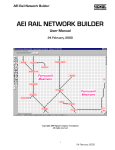


![Manual condicionador de sinal SD20 [PTBR]](http://vs1.manualzilla.com/store/data/006085115_1-891da68fb4d8bbd4bc5f0d8350060514-150x150.png)