1
USR-WIFI232-X V4.0 User Manual
http://en.usr.cn
2
USR-WIFI232-X- V4.
V4.2
Embedded WiFi Module User Manual
Overview of Characteristic
�
Support IEEE802.11b/g/n Wireless Standards
�
Support TCP/IP/UDP Network Protocols
�
Support UART/GPIO/Ethernet Data Interface
�
Support Work As STA/AP Mode
�
Support Router/Bridge Mode Networking
�
Support Internal/External Antenna Option
�
Support Transparent/Agreement Transmission Mode
�
Support AT+ Instruction Set for Configuration
�
Support Friendly Web Configuration Page
�
Support Palmodic Signal
�
Support UART Port Auto-Frame Function
�
Single +3.3V Power Supply
�
Small Size: 25 x 40mm
�
FCC/CE Certificated
�
Flexible Software Platform with Linux OS
Remarks: This module is applicable to USR-WIFI232-A/B/C/D and its derivatives,for USRWIFI232-2/600/62E.USR-WIFIMOD-II/USR-WIFI232-L and the series of different, please refer to
the corresponding document..
Jinan USR IOT Technology Co., Ltd.
Page 1 of 70
[email protected]
USR-WIFI232-X V4.0 User Manual
http://en.usr.cn
TABLE OF CONTENTS
1. Product Overview.......................................................................................................................... 8
1.1. General Specification............................................................................................................. 8
1.2. Hardware Introduction............................................................................................................9
1.2.1. Pins Definition.............................................................................................................. 9
1.2.2. Mechanical Size.........................................................................................................12
1.2.3. On-board Chip Antenna............................................................................................ 13
1.2.4. External Antenna....................................................................................................... 14
1.2.5. Evaluation Kit............................................................................................................. 15
1.3. Hardware Reference Design............................................................................................... 17
1.3.1. Hardware Typical Application....................................................................................17
1.3.2. 10/100M Ethernet Interface...................................................................................... 18
1.3.2.1. Ethernet Connection with Transformer..................................................................18
1.3.2.2. Ethernet Connection without Transformer............................................................ 18
1.3.3. UART Interface.......................................................................................................... 18
1.3.4. Power Interface..........................................................................................................19
1.4. Software Reference Design.................................................................................................19
1.4.1. Transparent Transmission Mode.............................................................................. 20
1.4.2. Agreement Transmission Mode................................................................................ 21
1.4.2.1. Agreement Transmission Data Structure.............................................................. 21
1.4.2.2. Agreement Transmission Procedure..................................................................... 22
1.4.2.3. Agreement Transmission CRC Arithmetic.............................................................24
1.4.3. Configuration Mode................................................................................................... 24
1.4.4. Multi-TCP Link Connection....................................................................................... 24
1.4.5. TCPB Function...........................................................................................................25
1.4.6. GPIO Function........................................................................................................... 25
1.4.7. Palmodic Signal......................................................................................................... 26
2. Functional Description................................................................................................................27
2.1. Wireless Networking............................................................................................................ 27
2.1.1. Basic Wireless Network Based On AP (Infrastructure)........................................... 27
2.1.2. Wireless Network Based On Adhoc Network (Adhoc).............................................27
2.1.3. Wireless Network Based On AP+STA...................................................................... 28
2.2. Auto- Frequency Function....................................................................................................29
2.3. Security................................................................................................................................. 29
2.4. UART Frame Scheme..........................................................................................................29
2.4.1. UART Free-Frame..................................................................................................... 29
2.4.2. UART Auto-Frame..................................................................................................... 30
2.5. Address Binding................................................................................................................... 30
2.6. Ethernet Interface Communication......................................................................................30
2.6.1. USR-WIFI232-X Ethernet Interface Networking (As AP)........................................ 31
2.6.2. USR-WIFI232-X Ethernet Interface Networking (As STA, N-Ver)...........................31
2.6.3. USR-WIFI232-X Ethernet Interface Networking (As STA, Z-Ver)........................... 31
2.7. Wireless Distribution System (WDS)...................................................................................32
2.8. Search Function for STA......................................................................................................32
Jinan USR IOT Technology Co., Ltd.
Page 2 of 70
[email protected]
USR-WIFI232-X V4.0 User Manual
http://en.usr.cn
2.9. Work Mode........................................................................................................................... 33
2.10. Network Protocol................................................................................................................ 34
2.11. Parameters Configuration.................................................................................................. 34
2.12. Firmware Upgrade............................................................................................................. 34
2.13. GPIO Function....................................................................................................................34
3. Operation Guideline.................................................................................................................... 35
3.1. Configuration via Web Accessing........................................................................................35
3.1.1. Open Web Management Interface........................................................................... 35
3.1.2. Mode Selection Page................................................................................................ 36
3.1.3. AP Interface Setting Page......................................................................................... 36
3.1.4. STA Interface Setting Page....................................................................................... 36
3.1.5. Application Setting Page........................................................................................... 37
3.1.6. Device Management Page........................................................................................38
3.2. USR-WIFI232-X Usage Introduction................................................................................... 38
3.2.1. Software Debug Tools............................................................................................... 38
3.2.2. Network Connection.................................................................................................. 38
3.2.3. Module Debug........................................................................................................... 39
3.2.4. Wireless Control Application..................................................................................... 41
3.2.5. Remote Management Application.............................................................................42
3.2.6. Transparent Serial Port Application.......................................................................... 42
3.2.7. Wireless Data Acquisition Card Application............................................................. 43
4. AT+instruction Introduction ........................................................................................................44
4.1. Configuration Mode..............................................................................................................44
4.1.1. Switch to Configuration Mode................................................................................... 44
4.2. AT+ Instruction Set Overview.............................................................................................. 45
4.2.1. Instruction Syntax Format......................................................................................... 45
4.2.2. AT+ Instruction Set.................................................................................................... 46
4.2.2.1. AT+E........................................................................................................................47
4.2.2.2. AT+ENTM................................................................................................................47
4.2.2.3. AT+NETP................................................................................................................ 48
4.2.2.4. AT+UART................................................................................................................ 48
4.2.2.5. AT+ UARTF.............................................................................................................49
4.2.2.6. AT+ UARTFT.......................................................................................................... 49
4.2.2.7. AT+ UARTFL...........................................................................................................49
4.2.2.8. AT+TMODE.............................................................................................................49
4.2.2.9. AT+WMODE........................................................................................................... 50
4.2.2.10. AT+WSKEY...........................................................................................................50
4.2.2.11. AT+WSSSID..........................................................................................................51
4.2.2.12. AT+ WSLK.............................................................................................................51
4.2.2.13. AT+WEBU............................................................................................................. 51
4.2.2.14. AT+WAP................................................................................................................52
4.2.2.15. AT+WAKEY...........................................................................................................52
4.2.2.16. AT+MSLP.............................................................................................................. 53
4.2.2.17. AT+WSCAN.......................................................................................................... 53
Jinan USR IOT Technology Co., Ltd.
Page 3 of 70
[email protected]
USR-WIFI232-X V4.0 User Manual
http://en.usr.cn
4.2.2.18. AT+ TCPLK........................................................................................................... 53
4.2.2.19. AT + TCPDIS........................................................................................................ 53
4.2.2.20. AT+ WANN............................................................................................................54
4.2.2.21. AT+ LANN............................................................................................................. 54
4.2.2.22. AT+ DHCPGW...................................................................................................... 55
4.2.2.23. AT+ TCPTO...........................................................................................................55
4.2.2.24. AT+ MAXSK.......................................................................................................... 55
4.2.2.25. AT+TCPB.............................................................................................................. 56
4.2.2.26. AT+TCPPTB......................................................................................................... 56
4.2.2.27. AT+TCPADDB.......................................................................................................56
4.2.2.28. AT+TCPTOB......................................................................................................... 56
4.2.2.29. AT+TCPLKB..........................................................................................................57
4.2.2.30. AT+EPHY.............................................................................................................. 57
4.2.2.31. AT+FUDLX............................................................................................................ 57
4.2.2.32. AT+RELD.............................................................................................................. 57
4.2.2.33. AT+Z...................................................................................................................... 58
4.2.2.34. AT+MID................................................................................................................. 58
4.2.2.35. AT+VER................................................................................................................ 58
4.2.2.36. AT+H..................................................................................................................... 58
5. Package Information ...................................................................................................................59
5.1 Shipping Information............................................................................................................. 59
Appendix A: Questions and Answers ........................................................................................... 60
Q1: How to configure transparent serial port application (TCP protocol) with two WIFI
modules?......................................................................................................................................60
Q2: Where to Set WIFI Module LAN IP and WAN IP through Web Page?............................ 60
Q3: How to configure transparent serial port application (UDP protocol) with two WIFI
modules?......................................................................................................................................61
Q4: Where to set USR-WIFI232-X module network protocol (TCP/UDP)?............................. 61
Q5: How to configure transparent serial port application: Two WIFI modules all configured as
STA and connection through AP?...............................................................................................62
Q6: How to avoid IP address confliction when apply USR-WIFI232-X module?..................... 63
Q7: PC works as server, all WIFI modules works as data acquisition card and connect with
PC, how to configure this application?....................................................................................... 63
Appendix b:evb reference design................................................................................................. 65
Appendix C: external power shutdown mode reference design.............................................66
Appendix d: User Device Pseudo-Code Reference For Agreement Transmission Mode.67
Appendix e: Contact Information.................................................................................................. 69
Jinan USR IOT Technology Co., Ltd.
Page 4 of 70
[email protected]
USR-WIFI232-X V4.0 User Manual
http://en.usr.cn
LIST OF FIGURES
Figure 1.USR-WIFI232-X......................................................................................................................8
Figure 2 USR-WIFI232-X Pins Map.....................................................................................................9
Figure 3 USR-WIFI232-X Mechanical Dimension.............................................................................13
Figure 4 USR-WIFI232-X Chip Antenna Keep Out Region.............................................................. 14
Figure 5 Suggested Module Placement Region................................................................................14
Figure 6 USR-WIFI232-X Evaluation Kit........................................................................................... 17
Figure 7 USR-WIFI232-X Hardware Typical Application.................................................................. 18
Figure 8 Ethernet Reference Design with Transformer.................................................................... 19
Figure 9 Ethernet Reference Design without Transformer............................................................... 19
Figure 10 UART Interface Reference Design....................................................................................20
Figure 11 User MCU Software Flow Chart........................................................................................ 21
Figure 12 User Device Send Data to USR-WIFI232-X Module Procedure..................................... 24
Figure 13 USR-WIFI232-X Module Send Data to User Device Procedure..................................... 25
Figure 14 Multi-TCP Link Data Transmission Structure....................................................................26
Figure 15 USR-WIFI232-X Functional Architecture.......................................................................... 28
Figure 16 USR-WIFI232-X Basic Wireless Network Structure.........................................................28
Figure 17 USR-WIFI232-X Adhoc Network Structure.......................................................................29
Figure 18 USR-WIFI232-X AP+STA Network Structure................................................................... 29
Figure 19 USR-WIFI232-X Ethernet Interface Networking (As AP)................................................. 32
Figure 20 USR-WIFI232-X Ethernet Interface Networking (As STA, N-Ver)................................... 32
Figure 21 USR-WIFI232-X Ethernet Interface Networking (As STA, Z-Ver)................................... 32
Figure 22 WDS Networking Demo.....................................................................................................33
Figure 23 USR-WIFI232-X Transparent Transmission Demo.......................................................... 35
Figure 24 Open Web Management page.......................................................................................... 36
Figure 25 Mode Selection Page.........................................................................................................37
Figure 26 AP Interface Setting Page................................................................................................. 37
Figure 27 STA Interface Setting Page............................................................................................... 38
Figure 28 Application Setting Page....................................................................................................38
Figure 29 Device Management Page................................................................................................ 39
Figure 30 Connection diagram........................................................................................................... 40
Figure 31 “CommTools” Serial Debug Tools......................................................................................41
Figure 32 “TCP UDPDbg” Tools Create Connection........................................................................41
Figure 33 The test results show that the network and serial port.....................................................42
Figure 34 Wireless Control Application..............................................................................................42
Figure 35 Remote Management Application..................................................................................... 43
Figure 36 Transparent Serial Port Application...................................................................................43
Figure 37 Wireless Data Acquisition Card Application......................................................................44
Figure 38 USR-WIFI232-X Default UART Port Parameters............................................................. 45
Figure 39 Switch to Configuration Mode........................................................................................... 45
Figure 40 ”AT+H” Instruction for Help............................................................................................... 46
Figure 41 Shipping Information.......................................................................................................... 60
Jinan USR IOT Technology Co., Ltd.
Page 5 of 70
[email protected]
USR-WIFI232-X V4.0 User Manual
http://en.usr.cn
LIST OF TABLES
Table 1
Table 2
Table 3
USR-WIFI232-X Module Technical Specifications.............................................................7
USR-WIFI232-X Pins Definition.......................................................................................... 9
USR-WIFI232-X External Antenna Parameters............................................................... 15
Table 4
Table 5
Table 6
Table 7
USR-WIFI232-X Evaluation Kit Interface Description......................................................17
USR-WIFI232-X Web Access Default Setting..................................................................36
Error Code DescribtionUSR-WIFI232-X Web Access Default Setting............................47
AT+ Instruction Set List......................................................................................................47
Jinan USR IOT Technology Co., Ltd.
Page 6 of 70
[email protected]
USR-WIFI232-X V4.0 User Manual
http://en.usr.cn
HISTORY
1 Created on 1-14-2012.
Ed. V3.
V3.1
0 Update AT command information on 6-25-2012.
Ed. V4.
V4.0
Ed.V4.1
Update 2.1.3 AT+STA function using notes and related commands
Add built-in antenna 1.2.3
Update Appendix B,C on 10-15--2012
Ed.V4.2
Update EVB reference design and picture
Jinan USR IOT Technology Co., Ltd.
Page 7 of 70
[email protected]
USR-WIFI232-X V4.0 User Manual
http://en.usr.cn
1. PRODUCT OVERVIEW
1.1. General Specification
Table 1
Class
Wireless
Parameters
USR-WIFI232-X Module Technical Specifications
Item
Parameters
Certification
FCC/CE
Wireless standard
Frequency range
802.11 b/g/n
2.412GHz-2.484GHz
802.11b: +20 dBm (Max.)
802.11g: +18 dBm (Max.)
802.11n: +15 dBm (Max.)
Configurable
802.11b: -89 dBm
802.11g: -81dBm
802.11n: -71dBm
External:I-PEX Connector
Internal:On-board chip antenna
UART: 1200bps - 230400bps
GPIOs
Ethernet: 100Mpbs
3.3V (+/-5%)
170mA~300mA
-25℃- 85℃
-40℃- 85℃
25×40×8mm
Transmit Power
Receiver Sensitivity
Antenna Option
Data Interface
Hardware
Parameters
Operating Voltage
Operating Current
Operating Temperature
Storage Temperature
Dimensions and Size
Network Type
Security Mechanisms
Encryption
Work Mode
Software
Parameters
Serial command
Network Protocol
Max. TCP Connection
User Configuration
User Application SW
Jinan USR IOT Technology Co., Ltd.
Station /AP mode
WEP/WAP-PSK/WAP2-PSK/WAPI
WEP64/WEP128/TKIP/AES
Transparent Transmission and
Agreement Transmission mode
AT+instruction set
TCP/UDP/ARP/ICMP/DHCP/DNS/HTT
P
32
Web Server+AT command config.
Support customized application SW with
Linux system.
Page 8 of 70
[email protected]
USR-WIFI232-X V4.0 User Manual
http://en.usr.cn
1.2. Hardware Introduction
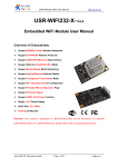
Figure 1.USR-WIFI232-X
1.2.1.
Pins Definition
Pin type module Pins Map:
P H Y _T X +
P H Y _T X -
P H Y _R X +
P H Y _R X -
nR eady /G P IO 9
nR eload /G P IO 1 0
R ES ET
n L in k /G P IO 8
U A R T _R T S /G P IO 5
U A R T_C T S /G P IO 6
U A R T _T X D /G P IO 3
U A R T_R X D /G P IO 4
GND
3.3V
SMD type module Pins Map:
Figure 2 USR-WIFI232-X Pins Map
Jinan USR IOT Technology Co., Ltd.
Page 9 of 70
[email protected]
USR-WIFI232-X V4.0 User Manual
Table 2
http://en.usr.cn
USR-WIFI232-X Pins Definition
Pin type module Definition:
Pin
Description
Name
1
2
3
Ground
VCC
UART Data Transmit
4
GPIO
UART Data Receive
GND
3.3V
UART_TX
D
GPIO3
UART_RX
D
GPIO4
UART_RT
S
GPIO5
5
6
GPIO
UART sends request of
data transmission
GPIO
Directio
n
Power
Power
O
I/O
I
I/O
UART_CT
S
I
GPIO6
RESET
I/O
I
8
WiFi status Indication
GPIO
nLink
GPIO8
O
I/O
9
Indicate the module
status of power on
process
GPIO
nReady
O
GPIO9
I/O
10
Restore configuration
GPIO
nReload
GPIO10
I
I/O
11
12
13
14
Ethernet Interface
PHY_RX+
I
Ethernet Interface
Ethernet Interface
Ethernet Interface
PHY_RXPHY_TX+
PHY_TX-
I
O
O
Jinan USR IOT Technology Co., Ltd.
3.3V @ 350mA power input
If not use UART function,this
4 pins can be configured as
GPIO pins, and can change
GPIO pin status through AT
command
I/O
O
UART receives data
transmission
permission
GPIO
Module reset signal
7
Note
Page 10 of 70
“Low ( 0 )” effective reset input.
The reset duration should be
kept more than 300ms
“1”- WIFI connection available,
“0”- No WIFI connection
Can be configured as GPIO.
“0” or “Palmodic Signal” Finish module boot up
process;
“1” - Module boot up not finish.
Can be configured as GPIO.
Module will Restore factory
default configuration after set
this pin “0” more than 1s, then
set “1”.
+1.8V Ethernet Data Interface
Support transformer and direct
connection (AC couple) mode.
[email protected]
USR-WIFI232-X V4.0 User Manual
http://en.usr.cn
SMD type module Definition:
Pin
Description
Name
Directi
on
3,18,19,
20,24,26
GND
GND
Power
Ground
1, 2
VCC
3.3V
Power
3.3V @ 350mA power
input
4
UART Data Transmit
UART_TXD
O
GPIO
GPIO
I/O
UART Data Receive
UART_RXD
I
GPIO
GPIO
I/O
UART sends request of
data transmission
UART_RTS
O
GPIO
GPIO
I/O
UART receives data
transmission permission
UART_CTS
I
GPIO
GPIO6
I/O
8
Ethernet Interface
PHY_TX+
O
9
Ethernet Interface
PHY_TX-
O
10
Ethernet Interface
PHY_RX+
I
11
Ethernet Interface
PHY_RX-
I
14
WiFi status Indication
nlink
O
“1”- WIFI connection
available, “0”- No WIFI
connection.Can be
configured as GPIO.
15
Module reset signal
nRST
I
“Low ( 0 )” effective
reset input.
The reset duration
should be kept more
than 300ms
5
6
7
Jinan USR IOT Technology Co., Ltd.
Page 11 of 70
Note
If not use UART
function, this 4 pins can
be configured as GPIO
pins, and can change
GPIO pin status
through AT command
+1.8V Ethernet Data
Interface(Module with
external 1.8V reference
voltage)
[email protected]
USR-WIFI232-X V4.0 User Manual
1.2.2.
http://en.usr.cn
16
Indicate the module status
of power on process
nReady
O
17
Restore configuration
nReload
I
21
UART1 Data Receive
UART_RXD
I
22
UART1 Data Transmit
UART_TXD
O
23
Output 1.8V
1.8V
O
1.8V@300mA,to
Eth application
25
2.4GHz Antenna
ANT
O
50ohm
impedance
control line
12,13
Retain
NC
NC
“0” - Finish module boot
up process;
“1” - Module boot up
not
finish.Can
be
configured as GPIO.
Module will Restore
factory
default
configuration after set
this pin “0” more than
1s, then set “1”.
5V biocompatible,with
port isolation
the
Mechanical Size
USR-WIFI232-X modules physical size as follows:
Pin type module Mechanical Size:
Jinan USR IOT Technology Co., Ltd.
Page 12 of 70
[email protected]
USR-WIFI232-X V4.0 User Manual
http://en.usr.cn
SMD module Mechanical Dimension:
Figure 3 USR-WIFI232-X Mechanical Dimension
1.2.3.
On-board Chip Antenna
USR-WIFI232-X supports a built-in antenna options, when customers choose a built-in antenna,
must comply with the following built-in antenna module placement of notes and general rules:
Jinan USR IOT Technology Co., Ltd.
Page 13 of 70
[email protected]
USR-WIFI232-X V4.0 User Manual
�
�
�
http://en.usr.cn
Be in the user's PCB board, and the red region ( 6X8MM ) corresponding to the region cannot be
placed components and with GND;
Antenna must away from the metal, at least to the distance around the higher components above
10MM;
Antenna cant be shielded by any meal enclosure; All cover, include plastic, shall away from antenna
at least 10MM;
Figure 4 USR-WIFI232-X Chip Antenna Keep Out Region
USR technological suggestions USR-WIFI232-X module be placed in the following areas of user
board, in order to reduce the antenna and a wireless signal influence, at the same time, please
consult with technology and technical support staff to assist module placement and associated
regions of Layout design.
Figure 5 Suggested Module Placement Region
1.2.4.
External Antenna
USR-WIFI232-X modules support internal antenna and external antenna option for user dedicated
application. If user select external antenna, USR-WIFI232-X modules must be connected to the 2.4G
antenna according to IEEE 802.11b/g/n standards.
The antenna parameters required as follows:
Table 3
USR-WIFI232-X External Antenna Parameters
Item
Parameters
Frequency range
2.4~2.5GHz
Impedance
VSWR
Return Loss
Connector Type
50 Ohm
2 (Max)
-10dB (Max)
I-PEX or populate directly
Jinan USR IOT Technology Co., Ltd.
Page 14 of 70
[email protected]
USR-WIFI232-X V4.0 User Manual
1.2.5.
http://en.usr.cn
Evaluation Kit
USR provides the evaluation kit to promote user to familiar the product and develop the detailed
application. The evaluation kit shown as below, user can connect to USR-WIFI232-X module with the
RS-232 UART port, 100M Eth port or Wireless port to configure the parameters, manage the module
or do the some functional tests.
Pin type module Evaluation Kit:
SMD module Evaluating Kit:
Jinan USR IOT Technology Co., Ltd.
Page 15 of 70
[email protected]
USR-WIFI232-X V4.0 User Manual
http://en.usr.cn
Figure 6 USR-WIFI232-X Evaluation Kit
The external interface description for evaluation kit as follows:
Table 4
USR-WIFI232-X Evaluation Kit Interface Description
Pin type module Evaluation Kit Interface Description:
Function
External
Interface
LED
Button
Name
Description
DC jack
5~18V power input connector
3-Pin
3-Pin RS485 interface
DB9
RJ-45
Module
Power (Red)
TXD
RXD
Ready
Link
Reset
Reload
Male serial jack of 9-pin,and used to connect to PC
100M Eth Interface
2x7 2mm DIP connector
3.3V Power Indicator
TXD Indicator
RXD Indicator
nReady/GPIO Indicator
nLink/GPIO Indicator
Used to reset the module.
Module restore to factory default configuration.
SMDmodule Evaluation Kit Interface Description:
Function
External
Interface
LED
Button
Name
DB9
RJ-45
Mini USB
Module
Power (Red)
CTS (Green 1)
RTS(Green 2)
Reload(Green
3)
Ready(Green 4)
Link(Green 5)
Reset
Reload
Jinan USR IOT Technology Co., Ltd.
Description
Male serial jack of 9-pin,and used to connect to
PC
100M Eth Interface
B-type interface,AS 5v@1A power input port
2x7 2mm DIP connector
3.3V Power Indicator
CTS/GPIO Indicator
RTS/GPIO Indicator
nReload/GPIO Indicator
nReady/GPIO Indicator
NLink/GPIO Indicator
Used to reset the module.
Module restore to factory default configuration.
Page 16 of 70
[email protected]
USR-WIFI232-X V4.0 User Manual
http://en.usr.cn
1.3. Hardware Reference Design
1.3.1.
Hardware Typical Application
Figure 7 USR-WIFI232-X Hardware Typical Application
Notes
Notes:
nRST- Module hardware reset signal. Input. Logics “0” effective.
There is 100K Ohm pull-up resister internal. When module power up or some issue happened, MCU
need assert nRST signal “0” at least 300ms, then set” 1” to keep module fully reset.
nReady- Module boot up ready signal. Output. Logics “0” effective.
There is 4.7K Ohm pull-up resister internal. The module will output “0” “or “Palmodic Signal” after
normal boot up. This signal used to judge if module finish boot up and ready for application or working
at normal mode.
nLink- Module WIFI connection indication. Output.
There is 4.7K Ohm pull-up resister internal. When module connect to AP (STA mode) or some WiFi
STA connect to module (AP mode), the module will output “0”. This signal used to judge if module
already at WiFi connection status.
nReload
nReload- Module restore to factory default configuration.Input. Logics “0” effective.
User can assert nReload signal “0” more than 3’s through button or MCU pin, then release, module will
restore to factory default configuration and re-start boot up process. User need add 4.7K~10K Ohm
pull-up resister external the module. If not use this function, then can use AT command
AT+FRLDEN=off to disable it.
Jinan USR IOT Technology Co., Ltd.
Page 17 of 70
[email protected]
USR-WIFI232-X V4.0 User Manual
http://en.usr.cn
UART_TXD/RXD
UART_TXD/RXD- UART port data transmit and receive signal.
There is 1K Ohm pull-down resister internal. User can’t add pull-up resister at these pins.
1.3.2.
10/100M Ethernet Interface
USR-WIFI232-X modules provide one 10/100M Ethernet PHY layer interface for data transition or user
configuration. This Ethernet support with transformer and without transformer (PHY-to-PHY) 2 kinds of
connection.
1.3.2.1. Ethernet Connection with Transformer
User board put Ethernet transformer and RJ-45 connector. This is a general 10/100M Ethernet phy
layer connection. The reference design as following:
Figure 8 Ethernet Reference Design with Transformer
1.3.2.2. Ethernet Connection without Transformer
For this application, Ethernet will work as internal data transmition interface and save one transformer
and RJ-45 connector. Ethernet PHY-to-PHY connection will use AC coupled connection. This is a
space and cost optimized solution. Hardware reference design as following:
Note: VCC signal at reference design shall base on user board PHY chipset voltage level, such as
2.5V power supply for general Ethernet PHY chipset.
Figure 9 Ethernet Reference Design without Transformer
1.3.3.
UART Interface
UART interface is the serial data transmition interface mainly used for USR-WIFI232-X modules.
User can add RS-232 chipset on user board and convert the signal to RS-232 voltage to communicate
with outside equipment or sensors. USR-WIFI232-X modules UART interface include 4 general
Jinan USR IOT Technology Co., Ltd.
Page 18 of 70
[email protected]
USR-WIFI232-X V4.0 User Manual
http://en.usr.cn
signals: TXD/RXD/RTS/CTS. The hardware reference design with RS-232 chipset as following:
Figure 10 UART Interface Reference Design
Notes : TXD pin is also hardware configuration pin internal module. So this pin MUST pull-down during
module power up. USR-WIFI232-X modules provide internal pull-down resister, user can’t add pullup/pull-down resister on user board, which may cause module can’t work.
1.3.4.
Power Interface
USR-WIFI232-X module support single +3.3V power supply. The peak current shall about 350mA and
normal WiFi working current shall about 200mA. The power save (WiFi OFF) mode will about 100mA
Decoupling at power pin suggested, At least one 100uF and one 10uF capacitor required at user
board and put near module power input pin will increase the reliability and performance.
1.4. Software Reference Design
When USR-WIFI232-X modules boot up phase, the general user board MCU software flow chart will
as following:
Jinan USR IOT Technology Co., Ltd.
Page 19 of 70
[email protected]
USR-WIFI232-X V4.0 User Manual
http://en.usr.cn
ow Chart
Figure 11 Use
Userr MCU Software Fl
Flow
USR-WIFI232-X modules provide two kinds of work mode and one configuration mode.
Work mode is Transparent Transmission and Agreement Transmission.
Configuration mode is through AT+instruction set to finish module setting and configuration.
When USR-WIFI232-X modules boot up, user can select one work mode base on the setting, and
user can switch to the configuration mode at any kinds of work mode.
1.4.1.
Transparent Transmission Mode
USR-WIFI232-X modules support serial interface transparent transmission mode. The benefit of
this mode is achieves a plug and play serial data port, and reduces user complexity furthest. In
this mode, user should only configure the necessary parameters. After power on, module can
automatically connect to the default wireless network and server.
As in this mode, the module's serial port always work in the transparent transmission mode, so
users only need to think of it as a virtual serial cable, and send and receive data as using a
simple serial. In other words, the serial cable of users’ original serial devices is directly replaced
with the module; user devices can be easy for wireless data transmission without any changes.
The transparent transmission mode can fully compatible with user’s original software platform
and reduce the software development effort for integrate wireless data transmission.
Notes
Notes: Transparent transmission mode as a low level phy layer data transmitting can't keep zero
error rates by itself. User can enable UART port’s hardware flow control CTS/RTS function or
though higher layer protocol such as TCP to lower error rate and mange the data completeness.
USR recommend when doing large amounts of data transmitting in transparent transmission
mode, hardware flow control should be enabled, so as to fully ensure reliable data transmission.
In the applications which doesn’t need flow control, users can simply leave RTS / CTS pin vacant.
Jinan USR IOT Technology Co., Ltd.
Page 20 of 70
[email protected]
USR-WIFI232-X V4.0 User Manual
1.4.2.
http://en.usr.cn
Agreement Transmission Mode
If user requires keep 100% accurate data transmitting (No error rate) or user board’ MCU has
limited data processing speed compared with wireless data transmitting rate, agreement
transmission mode is suggested in this kinds of application.
Agreement transmission mode defines transmission data structure, verification mode, connection
mode between both sides, which target to fully control and mange the data transmission on the
serial port. These kinds of mode can keep accurate data transmitting.
In agreement transmission mode, user device (or MCU) send “SEND” instruction to USRWIFI232-X modules, USR-WIFI232-X modules reply “SEND ACK” instruction to confirm. USRWIFI232-X modules will not active transmit the serial port data to user device, it only can transmit
the data after receive user device’s data transmit request. USR-WIFI232-X module has 1M byte
data FIFO to save data which need to be transmitting to the user device.
1.4.2.1. Agreement Transmission Data Structure
Agreement transmission mode’s command data structure and agreement as following:
- The 1st Byte of each frame is command word;
- The 2nd Byte of each frame is serial number (SN).
User device insert SN when it send command frame, the SN will increase one (SN+1)
after one frame successful transmission. SN shall reset to 0x00 after arrive 0xFF as a
cycle period.
- Data Length(Example: LLLL), which is the net length of data part .
Unit: Byte. Maximum: 1024 Bytes
- CRC Part(Example: CCCC), which is the CRC result of whole frame.
- Serial transmission sequence for “LLLL” and “CCCC”: Low byte first, then higher byte
SEND
� Data Transmit Command
Command(SEND
SEND)
�
�
User device use this command to send data to USR-WIFI232-X module
�
“SEND” frame structure:
0
1
01
SS
2
3
4
0000
5
6
N+5
DDDD … … DDDD
LLLL
�
Command Word: 01
�
Serial Number: SS
�
Reserve Part: 0000(All reserve part shall set to “0”)
�
Data Length: LLLL(Data part” DDDD….DDDD” length)
�
Data Content: DDDD……..DDDD
�
CRC Check: CCCC
N+6
N+7
CCCC
Data Transmit Acknowledge Command (SEND ACK)
Jinan USR IOT Technology Co., Ltd.
Page 21 of 70
[email protected]
USR-WIFI232-X V4.0 User Manual
�
http://en.usr.cn
USR-WIFI232-X module replies this command to acknowledge receive “SEND” frame
data.
�
“SEND ACK” frame structure:
�
�
0
1
01
SS
2
3
4
0000
XX
Command Word: 01
Serial Number: SS
(Serial Number need keep the same with “SEND” command’s serial number)
�
�
Reserve Part: 0000(All reserve part shall set to “0”)
�
Acknowledge Information: XX (”00” -- OK,”FF” or others --NOK)
RECV
Data Receive Request Command
Command(RECV
RECV)
�
User device use this command to send data receive request to USR-WIFI232-X
modules
�
�
“RECV” frame structure:
0
1
02
SS
2
3
4
0000
5
LLLL
6
7
CCCC
�
Command Word: 02
�
Serial Number: SS
�
Reserve Part: 0000(All reserve part shall set to “0”)
�
Request Data Length: LLLL
�
CRC Check: CCCC
Data Receive Acknowledge Command (RECV ACK)
�
USR-WIFI232-X module reply this command to acknowledge receive “RECV” command
and insert data (as user device request’s length or shorter) in the frame.
�
“RECV ACK” frame structure:
0
1
02
SS
2
3
0000
�
Command Word: 02
�
Serial Number: SS
4
5
6
LLLL
L+5
DDDD … … DDDD
L+6
L+7
CCCC
(Serial Number need keep the same with “RECV” command’s serial number)
�
Reserve Part: 0000(All reserve part shall set to “0”)
�
Data Length: LLLL (Length shall equal or shorter than request data length)
�
Data Content: DDDD……..DDDD
�
CRC Check: CCCC
1.4.2.2. Agreement Transmission Procedure
Agreement transmission mode procedure as following chart:
Jinan USR IOT Technology Co., Ltd.
Page 22 of 70
[email protected]
USR-WIFI232-X V4.0 User Manual
http://en.usr.cn
(This is a procedure user device hope to send data to USR-WIFI232-X module)
Figure 12 User Device Send Data to USR-WIFI232-X Module Procedure
Notes
Notes: For Error scheme 1, if USR-WIFI232-X receives wrong CRC information of “SEND” command,
it will reply back “SEND ACK”=NOK. If USR-WIFI232-X not receives “SEND” command for the link
issue, user device need decide to retry.
(This is a procedure USR-WIFI232-X module send data to user device procedure)
Jinan USR IOT Technology Co., Ltd.
Page 23 of 70
[email protected]
USR-WIFI232-X V4.0 User Manual
http://en.usr.cn
Figure 13 USR-WIFI232-X Module Send Data to User Device Procedure
1.4.2.3. Agreement Transmission CRC Arithmetic
CRC aarithmetic C language reference code as following:
----------------------------------------u16 calc_sum(void *data, u32 len)
{
u32 cksum=0;
u16 *p=data;
while (len > 1)
{
cksum += *p++;
len -=2;
}
if (len)
{
cksum += *(u8 *)p;
}
cksum = (cksum >> 16) + (cksum & 0xffff);
cksum += (cksum >>16);
return ~cksum;
}
--------------------------------------------1.4.3.
Configuration Mode
In configuration mode, user can finish USR-WIFI232-X module configuration management and
parameters setting work. In work mode (Transparent Transmission or Agreement Transmission), user
can switch to the configuration mode through AT+instruction, detailed switch operation refer to “AT+
instruction set” chapter.
Jinan USR IOT Technology Co., Ltd.
Page 24 of 70
[email protected]
USR-WIFI232-X V4.0 User Manual
1.4.4.
http://en.usr.cn
Multi-TCP Link Connection
When USR-WIFI232-X module configured as TCP Server, it supports Multi-TCP link connection, and
maximum 32 TCP clients permit to connect to USR-WIFI232-X module. User can realize multi-TCP
link connection at each work mode.
Multi-TCP link connection will work as following structure:
Upstream: All dates from different TCP connection or client will be transmitted to the serial port as a
sequence.
Downstream: All data from serial port (user) will be duplicate and broadcast to every TCP connection
or client.
Detailed multi-TCP link data transmission structure as following figure:
ss
ion Structure
Figure 14 Multi-TCP Link Data Transmi
Transmiss
ssion
1.4.5.
TCPB Function
USR-WIFI232-X support 2xTCP function, which means module can support 2 network connections at
the same time. The 2nd net work connection called TCPB. TCPB only works as TCP Client and its
configuration can only through AT command, not Web configuration supported. The command as
following,
�
AT+TCPB=on,
�
AT+TCPPTB=<port>, Set TCPB port number;
�
AT+TCPADDB=<IP or domain>, Set TCPB’s server address;
�
AT+TCPTOB=<time>, Set TCPB timeout;
�
AT+TCPLKB,
Enable TCPB function;
Query TCPB link status;
Detailed command description refer to AT instruction chapter. After enable TCPB function, two network
interfaces’ work mode like “Multi-TCP Link”, All dates from each TCP connection will be transmitted to
the serial port as a sequence and all data from serial port (user) will be duplicate and broadcast to
each TCP connection.
Jinan USR IOT Technology Co., Ltd.
Page 25 of 70
[email protected]
USR-WIFI232-X V4.0 User Manual
1.4.6.
http://en.usr.cn
GPIO Function
USR-WIFI232-X module support 2 GPIO mode: GPIO-1 and GPIO-2. At GPIO-1 mode, UART (TXD/
RXD/CTS/RTS) defined as GPIO and others (nReady/nLink/nReload) defined as functional pin. At
GPIO-2, all these 7 pins defined as GPIO. So, GPIO mode not supports UART communication.
When module works at GPIO mode, PC and other equipments can setup connection (TCP/UDP)
through WiFi, then read/write GPIO information through command.
�
GPIO n IN,
�
GPIO n OUT 0, Set GPIOn as output and output ‘0’, Response GPIO OK or GPIO NOK;
�
GPIO n OUT 1, Set GPIOn as output and output ‘1’, Response GPIO OK or GPIO NOK;
�
GPIO n SW,
Set GPIOn as input, Response GPIO OK or GPIO NOK;
Set GPIOn as output and switch the output status, Response GPIO OK or
GPIO NOK;
�
GPIO n PWM m1 m2, Set GPIOn output a wave: m1 is ‘high’ duration and m2 is ’low’
duration (Time unit is ‘ms’ and minimal is 10ms), Response GPIO OK or GPIO NOK;
�
GPIO n GET, Read GPIOn status, Response I0,I1,O0,O1, means”input low”,”input
high”,”output low”,”output high”
Notes: n can be 3, 4, 5, 6, 8, 9, 10 corresponding module pin. GPIO 4 and 10 can only defined as
input and GPIO 3 can only defined as output.
GPIO READ returns all current IO status, and GPIO n GET said method. Such as, I1I1I0I0I0I0O1, I
said input, O output. 0 low, 1 express high.4 and 10 of the two pin is negated. Read the 1 actual 0
actual 1, read the 0.
1.4.7.
Palmodic Signal
Base on selected factory default setting, nReady signal can have two output statuses:
�
Status One: The module will output “0” after normal boot up. This signal used to judge if
module finish boot up and ready for application.
�
Status Two: The module will output “Palmodic Signal” after normal boot up.The palmodic
signal is 0.5Hz square wave with dutyfactor 1:1. User can query this signal to judge if
moduleis active “live” or need to re-boot. When module switches to command mode, it will
output “0”, which used to distinguish work mode and command mode.
Notes
Notes:
This function is user selected factory setting and RELD instruction will not effective for this function. If
user not requires this function, the default factory setting is Status One. Contact with Hi-flying for more
detailed support.
Jinan USR IOT Technology Co., Ltd.
Page 26 of 70
[email protected]
USR-WIFI232-X V4.0 User Manual
http://en.usr.cn
2. FUNCTIONAL DESCRIPTION
2.1. Wireless Networking
USR-WIFI232-X module can be configured as both wireless STA and AP base on network type.
Logically there are two interfaces in USR-WIFI232-X. One is for STA, and another is for AP. When
USR-WIFI232-X works as AP, other STA equipments are able to connect to wireless LAN via USRWIFI232-X module. Wireless Networking with USR-WIFI232-X is very flexible.
Following figure shows the functional architecture of USR-WIFI232-X module:
Figure 15 USR-WIFI232-X Functional Architecture
Notes
Notes:
AP
AP: that is the wireless Access Point, the founder of a wireless network and the center of the
network nodes. The wireless router we use at home or in office may be an AP.
STA
STA: short for Station, each terminal connects to a wireless network (such as laptops, PDA and
other networking devices) can be called with a STA device.
2.1.1.
Basic Wireless Network Based On AP (Infrastructure)
Infrastructure: it’s also called basic network. It built by AP and many STAs which join in.
The characters of network of this type are that AP is the center, and all communication between
STAs is transmitted through the AP. The figure following shows such type of networking.
Figure 16 USR-WIFI232-X Basic Wireless Network Structure
2.1.2.
Wireless Network Based On Adhoc Network (Adhoc)
Adhoc: It’s also called independent basic service set, and it’s built by two or more STAs without
Jinan USR IOT Technology Co., Ltd.
Page 27 of 70
[email protected]
USR-WIFI232-X V4.0 User Manual
http://en.usr.cn
AP, this type of network is a loose structure, all the STAs in the network can communicate directly.
As showing in the figure below, USR-WIFI232-X (1) can be treat as an AP, and USR-WIFI232-X
(2), USR-WIFI232-X (3) and the laptop are STAs connected to USR-WIFI232-X (1). Meanwhile,
all USR-WIFI232-X modules can connected to user device via UART interface. All USR-WIFI232X modules can be operated and managed through the laptop. So it is convenient to O&M all
USR-WIFI232-X modules. Moreover, in such Adhoc network structure, the whole coverage of a
wireless network can be extended easily.
Figure 17 USR-WIFI232-X Adhoc Network Structure
2.1.3.
Wireless Network Based On AP+STA
USR-WIFI232-X module support AP+STA network mode, means module support one AP interface and
one STA interface at the same time, as following figure,
Figure 18 USR-WIFI232-X AP+STA Network Structure
When module enables AP+STA function, Module’s STA interface can connect with router and connect
to TCP server in the network. At the same time, module’s AP interface is also active and permit
Jinan USR IOT Technology Co., Ltd.
Page 28 of 70
[email protected]
USR-WIFI232-X V4.0 User Manual
http://en.usr.cn
phone/PAD to connect through TCPB, then phone/PAD can control user device and and setting the
module parameters,
The advantage of AP+STA mode is:
�
Users can easily setting and track user device through Phone/PAD and not change the
orginal network setting.
�
Users can easily setting module’s parameters through WiFi when module works as STA
mode.
AP+STA Mode Setting:
AP+STA mode need serial AT command to enable as follows:
�
AT+FAPSTA=on, Enable AP+STA mode;
�
Then, when you configure module works as STA mode, it’s AP interface still active;
AP+STA Mode Notes:
When user enable AT+STA function,the STA port need to keep connected with other router(AP),
or STA port will have to scan the AP frequently ,which will affect AP port function and may cause some
date loss.
So ,if user confirm STA port can't connect with AP at some time,user can disable the STA scan
through the following command:
�
AT+STTC=on/off
AT+STTC=on/off,on:Scan AP;off:NO Scan AP.
�
AT+FSTTC=on/off
AT+FSTTC=on/off;
After re-start module,this command not saved;
This command is saved after re-staring the module;
2.2. Auto- Frequency Function
When module works as STA, USR-WIFI232-X will adjust its wireless channel to keep the same
channel with associated AP and connect in.
When module works as AP and USR-WIFI232-X enable Auto-frequency function, then when
module boot up, it will select the best wireless channel based on surrounding environment.
2.3. Security
USR-WIFI232-X module supports multiple wireless encryption mechanisms, and enables to
protect the security of user’s data transmission, the mechanisms include:
�
WEP
�
WPA-PSK/TKIP
�
WPA-PSK/AES
�
WPA2-PSK/TKIP
�
WPA2-PSK/AES
2.4. UART Frame Scheme
2.4.1.
UART Free-Frame
USR-WIFI232-X support UART free-frame function. If user select open this function, module will check
the intervals between any two bytes when receiving UART data. If this interval time exceeds defined
Jinan USR IOT Technology Co., Ltd.
Page 29 of 70
[email protected]
USR-WIFI232-X V4.0 User Manual
http://en.usr.cn
value (50ms default), USR-WIFI232-X will think it as the end of one frame and transfer this free-frame
to WiFi port, or USR-WIFI232-X will receive UART data until 4K bytes, then transfer 4KB frame to WiFi
port.
USR-WIFI232-X’s default interval time is 50ms. User can also set this interval to fast (10ms) through
AT command. But user have to consider if user MCU can send UART data with 10ms interval ,or the
UART data may be divide as fragment.
Through AT command: AT+FUARTTE=fash/normal, user can set the interval time: fast (10ms) and
normal (50ms). This command is factory default setting command and AT+RELD can’t change its
value.
2.4.2.
UART Auto-Frame
USR-WIFI232-X support UART auto-frame function. If user select open this function and setting autoframe trigger length and auto-frame trigger time parameters, then module will auto framing the data
which received from UART port and transmitting to the network as pre-defined data structure.
�
Auto-frame trigger length
length: The fixed data length that module used to transmitting to the
network.
�
Auto-frame trigger time: After the trigger time, if UART port received data can’t reach autoframe trigger length, then module will transmitting available data to the network and bypass
the auto-frame trigger length condition.
Detailed UART auto-frame function can refer to AT+ instruction set “UARTF/UARTFT/UARTFL”
introduction.
2.5. Address Binding
USR-WIFI232-X module supports the feature of binding the BSSID address of target network.
According to the provisions of 802.11 protocol, different wireless networks can have a same
network name (i.e. SSID / ESSID), but must correspond to a unique BSSID address (i.e. MAC
address). Illegal intruders can create a wireless network with the same SSID / ESSID, it will make
STAs in the network to join to the illegal AP, thereby and then network leakage happen.
Users can prevent STA from joining to illegal network by binding the BSSID address, to improve
wireless network security.
2.6. Ethernet Interface Communication
USR-WIFI232-X module provides one 10/100M Ethernet interface. With this Ethernet interface,
user can easily realize the three interface (WiFi, UART, and Ethernet) intercommunication and
networking. USR-WIFI232-X module can configured as Bridge Mode or Router Mode base on
different networking technology.
Notes: For different networking requirement, USR-WIFI232-X may need different firmware to
Jinan USR IOT Technology Co., Ltd.
Page 30 of 70
[email protected]
USR-WIFI232-X V4.0 User Manual
http://en.usr.cn
support this function (Such as “N-Ver” and “Z-Ver” as following, which need customized firmware
as customer detailed requirement). So, please contact with USR technical support interface to
know more about Ethernet interface networking application.
2.6.1.
USR-WIFI232-X Ethernet Interface Networking (As AP)
Figure 19 USR-WIFI232-X Ethernet Interface Networking (As AP)
For above networking, USR-WIFI232-X module works as AP and also the center of this network. All
devices’ IP address in this network shall use the same network segment with USR-WIFI232-X and
they can intercommunication with this method.
2.6.2.
USR-WIFI232-X Ethernet Interface Networking (As STA, N-Ver)
Figure 20 USR-WIFI232-X Ethernet Interface Networking (As STA
STA,, N-Ver
N-Ver))
For above networking, USR-WIFI232-X module works as STA(Firmware is N-Version),and module
configured as router mode. When module connect to AP, it will get wireless port IP address from AP
( For example: 192.168.1.100 ) .At the same time, module also form a subnet ( Default
10.10.100.254)and all devices connected to module Ethernet interface will get assigned IP address
( For example: 10.10.100.101 ) .So for above networking, PC1 at internal subnet can initiate a
connection to PC2 (For USR-WIFI232-X works as router mode), but PC2 can’t active initiate a
connection to PC1.
2.6.3.
USR-WIFI232-X Ethernet Interface Networking (As STA, Z-Ver)
Figure 21 USR-WIFI232-X Ethernet Interface Networking (As STA
STA,, Z-Ver
Z-Ver))
Jinan USR IOT Technology Co., Ltd.
Page 31 of 70
[email protected]
USR-WIFI232-X V4.0 User Manual
http://en.usr.cn
For above networking, USR-WIFI232-X module works as STA(Firmware is Z-Version),and module
configured as bridge mode. When module connect to AP, all devices connected to module Ethernet
interface will get assigned IP address from AP (For example: 192.168.1.101).For module works as
bridge mode, it can be treated as a transparent device and PC1, PC2 can communicate without any
limit. But in this networking, USR-WIFI232-X module needs assign a static LAN IP address (For
example: 192.168.1.10) if module also needs communication with AP or configuration through web
page.
2.7. Wireless Distribution System (WDS)
USR-WIFI232-X support Wireless Distribution System (WDS) function. Through WDS, serval APs can
connect each other and build a big WiFi network.
WDS network structure as following figure, the center 3 USR-WIFI232-X work as AP mode and enable
WDS function; they build a big WDS network. All other USR-WIFI232-X work as STA mode and can
connect with any AP in the WDS network. All modules include AP and STA are in the same local area
network (LAN).
The server can connect with one AP through WiFi or Ethernet connection, then server can connect
with every user device and control them as in the same local area network.
Through AT command AT+FVER=w to enable WDS function. Also WDS function can set through the
web page.
Figure 22 WDS Networking Demo
2.8. Search Function for STA
When using web configuration STA Interface Setting Page, user can push “Search” button to find
surrounding AP, and find a AP to associated.
Jinan USR IOT Technology Co., Ltd.
Page 32 of 70
[email protected]
USR-WIFI232-X V4.0 User Manual
http://en.usr.cn
2.9. Work Mode
USR-WIFI232-X modules provide two kinds of work mode: Transparent transmission mode and
Agreement Transmission mode. Transparent transmission mode achieves a plug and play serial
data port, and reduces user complexity. Agreement Transmission mode can keep 100% accurate
data transmitting. User can configure dedicated work mode base on actual requirement, and save
the configuration information to the flash of USR-WIFI232-X, then module will go into the
appointed work mode after power up.
For a module which already finished parameters setting, it will try to connect a wireless network and
server with these parameters after power up, and serial interface is also active with pre-configured
parameters. Then all the data is transferred directly between serial interface and Wifi interface without
any interpreted.
The parameters which need to configure include:
�
�
�
�
Wireless Network Parameters
�
Wireless Network Name(SSID)
�
Security Mode
�
Encryption Key
TCP/UDP Linking Parameters
�
Protocol Type
�
Link Type(Server or Client)
�
Target Port ID Number
�
Target Port IP Address
Serial Port Parameters
�
Baud Rate
�
Data Bit
�
Parity (Check) Bit
�
Stop Bit
�
Hardware Flow Control
Work Mode Selection
�
Transparent transmission or Agreement Transmission mode
Transparent transmission demo as showing in the following figure, a USR-WIFI232-X module can be
taken as a virtual serial line when UART interface working in transparent transmission mode. And user
device will realize wireless data transmission almost without any changes.
Jinan USR IOT Technology Co., Ltd.
Page 33 of 70
[email protected]
USR-WIFI232-X V4.0 User Manual
http://en.usr.cn
Figure 23 USR-WIFI232-X Transparent Transmission Demo
Network Protocol
2.10.
2.10.Network
USR-WIFI232-X module supports TCP/UDP network protocol and the port parameters can be set
via web accessing or AT+instruction set.
2.11. Parameters Configuration
USR-WIFI232-X module supports two methods to configuration parameters: Web Accessing and
AT+instruction set
set.
Web accessing means users can configure parameters through Web browser. When USRWIFI232-X module connected to wireless network, parameters configuration is done on a PC
connected to the same wireless network. AT+instruction set configuration means user configure
parameters through serial interface command. Refer to “AT+instruction set” chapter for more
detail.
Notes:
USR can customized the parameters setting as customer request and ship USR-WIFI232-X
modules with these parameters as factory default configuration. It will reduce user’s module
configuration time for mass production. Also, if user need different parameters setting for every
module, USR can provide the auto-configuration tool to speed up the module configuration
duration. Please contact USR technical interface to acquire this tool if required.
2.12.
Firmware Upgrade
2.12.Firmware
USR-WIFI232-X module supports firmware upgrade online; User can upgrade firmware via web
access.
GPIO Function
2.13.
2.13.GPIO
USR-WIFI232-X module can provide maximum 7 GPIO pins, Refer to “1.2.1 Pin Definition” charter,
which include 4 UART pins and 3 general use pins can be customized as GPIO pins if these functions
are not required. As GPIO functional pin, user devices can read/write GPIO pins status through
AT+instruction set.
Jinan USR IOT Technology Co., Ltd.
Page 34 of 70
[email protected]
USR-WIFI232-X V4.0 User Manual
http://en.usr.cn
3. O PERATION G UIDELINE
3.1. Configuration via Web Accessing
When first use USR-WIFI232-X modules, user may need some configuration. User can connect to
USR-WIFI232-X module’s wireless interface with following default setting information and configure
the module through laptop.
Table 5
3.1.1.
USR-WIFI232-X Web Access Default Setting
Parameters
SSID
Default Setting
HF-A11_AP
IP Address
10.10.100.254
Subnet Mask
255.255.255.0
User Name
Password
admin
admin
Open Web Management Interface
Step 1: Connect laptop to SSID “USR-WIFI232-X_AP” of USR-WIFI232-X module via wireless LAN
card;
http://10.10.100.254
Step 2: After wireless connection OK. Open Wen browser and access “http://10.10.100.254
http://10.10.100.254”;
Step 3: Then input user name and password in the page as following and click “OK” button.
Figure 24 Open Web Management page
The USR-WIFI232-X web management page support English and Chinese language. User can select
language environment at the top right corner and click “Apply” button.
The main menu include five pages: “Mode Selection”,” AP Interface Setting”,”STA Interface
Setting”,”Application Setting”, and “Device Management”
Notes:
Default, USR suggests all Web management related operation shall execute at AP mode. (Even you
need configure STA parameters and want module works as STA mode). If user selects STA mode and
still want to configurate the module through Web browser, you have to access the module through
another AP (and get the module IP address through this AP)
Jinan USR IOT Technology Co., Ltd.
Page 35 of 70
[email protected]
USR-WIFI232-X V4.0 User Manual
3.1.2.
http://en.usr.cn
Mode Selection Page
This page use to setting the module working mode (Transparent Transmission or Agreement
Transmission) and wireless networking mode (AP and STA mode).
Figure 25 Mode Selection Page
3.1.3.
AP Interface Setting Page
This page use to setting the parameters when USR-WIFI232-X module works as AP.
Figure 26 AP Interface Setting Page
3.1.4.
STA Interface Setting Page
This page use to setting the parameters when USR-WIFI232-X module works as STA.
Such as SSID of AP which module need to connected, and also select the networking type: DHCP or
static IP address.
Jinan USR IOT Technology Co., Ltd.
Page 36 of 70
[email protected]
USR-WIFI232-X V4.0 User Manual
http://en.usr.cn
Figure 27 STA Interface Setting Page
3.1.5.
Application Setting Page
This page use to setting the parameters of serial port communication, such as UART setting and high
layer network protocol setting which used support serial communication.
Figure 28 Application Setting Page
Notes:
Generally, Network protocols support three modes: TCP Server
Server, TCP Client
Client, and UDP
UDP. UDP has
no server and client requirement according to standard.
Jinan USR IOT Technology Co., Ltd.
Page 37 of 70
[email protected]
USR-WIFI232-X V4.0 User Manual
http://en.usr.cn
Besides module working as TCP Server (IP address not required in this mode). User must set the IP
address of the device which need communicate with USR-WIFI232-X module.
Also the Port ID between two sides of the communication devices must keep the same.
3.1.6.
Device Management Page
This page use to manage USR-WIFI232-X module general setting, such as administrator setting,
restart module button, restore factory default setting button, and update firmware through webpage.
Figure 29 Device Management Page
Notes:
Restart module button: When you setting the parameters of different web pages, you will click
“Apply” button to confirm the setting, but the setting take effect only after user click the “Restart”
button here, the module will re-boot up and refresh the memory information with new changes.
3.2. USR-WIFI232-X Usage Introduction
3.2.1.
Software Debug Tools
In order to facilitate the use of my company, development of the serial and network
debugging two-in-one test software,USR-TCP232-Test
Jinan USR IOT Technology Co., Ltd.
Page 38 of 70
[email protected]
USR-WIFI232-X V4.0 User Manual
3.2.2.
http://en.usr.cn
Network Connection
In order to test the serial port to the WIFI network address conversion, we will module serial
connected with the computer, network and computer links to WIFI.
Due to the need to have both a WIFI and serial special requirements, only a minority of the
notebook computer can achieve, the user can use the desktop with a USB card, or use the
notebook computer with a USB to serial line way, the author uses the desktop and WIFI card
form test, desktop with serial. ( Note: there USB transfer RS232 the line quality uneven,
some good and some bad, in order not to waste your valuable time, look for buying a used
FT232 chip scheme suggested switching line, about the price $9)
Figure 30 Connection diagram
On the serial connection, module pin leads to 3.3V TTL level, not directly connected with the computer,
need to bring the bottom or users are TTL to RS232 connecting line connected to the computer, in
order to facilitate the user to test the use of, we provide a variety of floor for the user to choose, here in
the case of USR-WIFI232-2.
Hardware connectivity, for module power supply, the red power indicator light, wait about 20 seconds
( internal LINUX system boot ), Ready lights, said system startup complete, can operate, entering the
next step.
3.2.3.
Module Debug
As shown above, opened in PC program, set the COM export and open the serial port connection
Jinan USR IOT Technology Co., Ltd.
Page 39 of 70
[email protected]
USR-WIFI232-X V4.0 User Manual
http://en.usr.cn
Figure 31 “CommTools
CommTools”” Serial Debug Tools
Open test software USR-TCP232-Test.exe, selection of hardware attached to the computer's serial
number, this is COM1, choose 57600 baud rate, such as the WIFI module serial default baud rate,
open the serial port.
Network settings in TCP client mode, the server IP address input 10.10.100.254, this is WIFI module
default IP address, server port number 8899, this module default monitor TCP port number, click the
link to establish TCP connection,Then click the create connection.
Dbg
Figure 32 “TCP UDP
UDPDbg
Dbg”” Tools Create Connection
Jinan USR IOT Technology Co., Ltd.
Page 40 of 70
[email protected]
USR-WIFI232-X V4.0 User Manual
http://en.usr.cn
Because of the USR-WIFI232-X module default support for transparent transmission mode, so now
you can debug tools two-way data, all data will be wholly intact transmission to the other side of
display. The testing process can be seen in module TXD and RXD indicator lights in the data through
the flashing.
Figure 33 The test results show that the network and serial port
Special note: because of the RTS/CTS pin processing difference, currently available
on the part of the serial debugging software for the module of the system is not
available, please be sure to want to use USR-TCP232-Test we provide testing, or just
RXD TXD GND connected the three line to the computer, please leave.
3.2.4.
Wireless Control Application
Figure 34 Wireless Control Application
Jinan USR IOT Technology Co., Ltd.
Page 41 of 70
[email protected]
USR-WIFI232-X V4.0 User Manual
http://en.usr.cn
For this wireless control application, USR-WIFI232-X works as AP mode. Module’s serial port
connects to user device. So, control agent (Smart phone for this example) can manage and control the
user device through the wireless connection with USR-WIFI232-X module.
3.2.5.
Remote Management Application
Figure 35 Remote Management Application
For this remote management application, USR-WIFI232-X works as STA mode and connects to
Internet through wireless AP. Module configured as TCP Client and communicates with remote TCP
server at Internet. Module’s serial port connects to user device.
So, user device’s data or sampling information can send to remote TCP server for storage or
processing. Also remote TCP server can send command to control and manage the user device
through the wireless network.
3.2.6.
Transparent Serial Port Application
For this transparent serial port application, two USR-WIFI232-X modules connect as below figures to
build up a transparent serial port connection.
Figure 36 Transparent Serial Port Application
For left side USR-WIFI232-X module, configured as AP mode and use default SSID and IP address,
network protocol configured as TCP/Server mode, and protocol port ID: 8899.
Jinan USR IOT Technology Co., Ltd.
Page 42 of 70
[email protected]
USR-WIFI232-X V4.0 User Manual
http://en.usr.cn
For right side USR-WIFI232-X module, configured as STA mode and setting the same SSID ( ”HFA11_AP” for this example)with left side USR-WIFI232-X module, enable DHCP network and network
protocol configured as TCP/Client mode, protocol port ID: 8899. Target IP address part setting the
same IP address with left side USR-WIFI232-X module (“10.10.100.254” for this example).
When right side USR-WIFI232-X boot up, it will find wireless AP (SSID:HF-A11_AP for this example)
and open TCP/Client network protocol to connect with left side module’s TCP/Server. All these
operation will be automatic and after finished, the two user devices connected to USR-WIFI232-X
module through serial port can communicate each other and think the connection between them is
fully transparent.
3.2.7.
Wireless Data Acquisition Card Application
For this wireless data acquisition card application, one PC works as data server and every data
acquisition card connects with a USR-WIFI232-X module to support wireless connection function.
Figure 37 Wireless Data Acquisition Card Application
As above figure, one USR-WIFI232-X configured as AP mode and all others configured as STA mode.
All USR-WIFI232-X which configured as STA and data server PC wireless connected to USRWIFI232-X which configured as AP to make up a wires network.
Data server PC open TCP/Server protocol and all USR-WIFI232-X modules open TCP/Client protocol.
All data acquisition cards’ data and sampling information can be transmitted to data server PC for
operation.
Jinan USR IOT Technology Co., Ltd.
Page 43 of 70
[email protected]
USR-WIFI232-X V4.0 User Manual
http://en.usr.cn
4. AT+INSTRUCTION INTRODUCTION
4.1. Configuration Mode
When USR-WIFI232-X power up, it will default works as transparent transmission mode, then user
can switch to configuration mode by serial port command. USR-WIFI232-X UART default parameters
setting as below figure,
Figure 38 USR-WIFI232-X Default UART Port Parameters
In configuration mode, user can setting the module through AT+ instruction set, which cover all web
page setting function.
4.1.1.
Switch to Configuration Mode
Two steps to finish switching from transparent transmission mode to configuration mode.
�
UART input “+++
+++””, after module receive “+++
+++””, and feedback “a” as confirmation.
�
UART input “a”, after module receive “a” and feedback “+ok
+ok”” to go into AT+
instruction set configuration mode.
Figure 39 Switch to Configuration Mode
Notes:
1. When user input “+++” (No “Enter” key required), the UART port will display feedback information
“a”, and not display input information”+++” as above UART display.
Jinan USR IOT Technology Co., Ltd.
Page 44 of 70
[email protected]
USR-WIFI232-X V4.0 User Manual
http://en.usr.cn
2. Any other input or wro ng step to UART port will cause the module still works as original mode
(transparent transmission).
4.2. AT+ Instruction Set Overview
User can input AT+ Instruction through hyper terminal or other serial debug terminal, also can program
the AT+ Instruction to script. User can also input “AT+H” to list all AT+ Instruction and description to
start.
Figure 40 ” AT+H
AT+H”” Instruction for Help
4.2.1.
Instruction Syntax Format
AT+Instruction protocol is based on the instruction of ASCII command style, the description of
syntax format as follow.
� Format Description
� < >: Means the parts must be included
� [ ]: Means the optional part
�
Command Message
…]<CR>
AT+<CMD>[op][para-1,para-2,para-3,para-4
AT+<CMD>[op][para-1,para-2,para-3,para-4…
�
AT+:
�
CMD: Command string;
�
[op]:
�
Prefix of command message;
Symbol of command operator,
�
“=” : The command requires parameters input;
�
“NULL”: Query the current command parameters setting;
[para-n]: Parameters input for setting if required;
Jinan USR IOT Technology Co., Ltd.
Page 45 of 70
[email protected]
USR-WIFI232-X V4.0 User Manual
�
http://en.usr.cn
<CR>:”Enter” Key, it’s 0x0a or 0x0d in ASCII;
Notes: When input AT+Instruction, “AT+<CMD>” character will display capital letter automatic
and other parts will not change as you input.
�
Response Message
…]<CR><LF><CR><LF>
+<RSP>[op] [para-1,para-2,para-3,para-4
[para-1,para-2,para-3,para-4…
�
�
+: Prefix of response message;
�
RSP: Response string;
�
“ok” : Success
�
“ERR”: Failure
�
[op] : =
�
[para-n]: Parameters if query command or Error code when error happened;
�
<CR>: ASCII 0x0d;
�
<LF>: ASCIII 0x0a;
Error Code
Table 6
4.2.2.
Error Code Description USR-WIFI232-X Web Access Default Setting
Error Code
-1
-2
Description
Invalid Command Format
Invalid Command
-3
-4
-5
Invalid Operation Symbol
Invalid Parameter
Operation Not Permitted
AT+ Instruction Set
Table 7
Instruction
<null>
E
ENTM
NETP
UART
UARTF
UARTFT
UARTFL
TMODE
WMODE
WSKEY
WSSSID
WSLK
WEBU
AT+ Instruction Set List
Description
NULL
Open/Close show back function
Set module into transparent transmission mode
Set/Query network protocol parameters
Set/Query serial port parameters
Open/Close UART auto-frame function
Set/Query UART auto-frame trigger time
Set/Query UART auto-frame trigger length
Set/Query data transmission mode
(transparent transmission or agreement transmission)
Set/Query WIFI work mode (AP or STA)
Set/Query WIFI security parameters as STA
Set/Query WIFI target AP SSID parameters as STA
Query WiFi link status as STA
Set/Query WEB page login parameters
Jinan USR IOT Technology Co., Ltd.
Page 46 of 70
[email protected]
USR-WIFI232-X V4.0 User Manual
http://en.usr.cn
(User Name and Password)
WAP
WAKEY
MSLP
WSCAN
TCPLK
TCPDIS
WANN
LANN
DHCPGW
TCPTO
MAXSK
TCPB
TCPPTB
TCPADDB
TCPTOB
TCPLKB
EPHY
RELD
Z
MID
VER
H
Set/Query WIFI parameters as AP
Set/Query WIFI security parameters as AP
Set modules into power save mode.(Turn OFF WiFi)
Seek AP when module works as STA mode
Query if TCP link already build-up
Open/Cose TCP (Only TCP Client available)
Set/Query WAN setting, only effective as STA mode
Set/Query LAN setting, only effective as AP mode
Set/Query DHCP gateway address
Set/Query TCP timeout
Set/Query maxima TCP connection
Open/Close TCPB function
Set/Query TCPB port number
Set/Query TCPB server address
Set/Query TCPB time out time
Query TCPB link status
Open/Close ETH interface
Restore to factory default setting
Re-start module
Query module ID information
Query module software version information
Help
Notes: USR-WIFI232-X module can works as AP or STA, user have to use different AT+ Instruction to
set WiFi parameters when module works as AP or STA mode.
4.2.2.1. AT+E
�
Function: Open/Close show back function;
�
Format:
AT+E<CR>
+ok<CR>< LF ><CR>< LF >
When USR-WIFI232-X module firstly switch from transparent transmission to configuration mode,
show back status is open, input “AT+E” to close show back function, input“AT+E” again to open show
back function.
4.2.2.2. AT+ENTM
�
Function: Set module into transparent transmission mode;
�
Format:
AT+ENTM<CR>
+ok<CR>< LF ><CR>< LF >
When operate this command, module switch from configuration mode to transparent transmission
mode.
Jinan USR IOT Technology Co., Ltd.
Page 47 of 70
[email protected]
USR-WIFI232-X V4.0 User Manual
http://en.usr.cn
4.2.2.3. AT+NETP
�
Function: Set/Query network protocol parameters;
�
Format:
�
Query Operation
AT+NETP<CR>
+ok=<protocol,CS,port,IP><CR>< LF ><CR>< LF >
�
Set Operation
AT+NETP=<protocol,CS,port,IP><CR>
+ok<CR>< LF ><CR>< LF >
�
Parameters:
�
�
protocol:
�
TCP
�
UDP
CS: Network mode:
�
SERVER
�
CLIENT
�
Port: protocol port ID: Decimal digit and less than 65535
�
IP: Server’s IP address when module set as client
After USR-WIFI232-X module boots up again, the setting will be effective.
4.2.2.4. AT+UART
�
Function: Set/Query serial port parameters;
�
Format:
�
Query Operation
AT+UART<CR>
+ok=<baudrate,data_bits,stop_bit,parity,flowctrl><CR>< LF ><CR>< LF >
�
Set Operation
AT+UART=<baudrate,data_bits,stop_bit,parity><CR>
+ok<CR>< LF ><CR>< LF >
�
Parameters:
�
baudrate:
�
50,75,110,134,150,200,300,600,1200,1800,2400,4800,9600,19200,38400,576
00,115200,230400,345600,460800
�
data_bits:
�
�
�
�
1,2
parity:
�
�
5,6,7,8
stop_bits:
NONE,EVEN,ODD,MARK,SPACE
flowctrl:hardware flow control (CTSRTS)
�
NFC: No flow control
�
FC: flow control
After USR-WIFI232-X module boots up again, the setting will be effective.
Jinan USR IOT Technology Co., Ltd.
Page 48 of 70
[email protected]
USR-WIFI232-X V4.0 User Manual
http://en.usr.cn
4.2.2.5. AT+ UARTF
�
Function: Open/Close UART auto-frame function;
�
Format:
�
Query Operation
AT+ UARTF<CR>
+ok=<para><CR>< LF ><CR>< LF >
�
Set Operation
AT+ UARTF=<para ><CR>
+ok<CR>< LF ><CR>< LF >
�
Parameters:
�
para:
�
disable
- Close auto-frame function;
�
enable
- Open auto-frame function;
4.2.2.6. AT+ UARTFT
�
Function: Set/Query UART auto-frame trigger time;
�
Format:
�
Query Operation
AT+ UARTFT<CR>
+ok=<time><CR>< LF ><CR>< LF >
�
Set Operation
AT+ UARTFT=<time ><CR>
+ok<CR>< LF ><CR>< LF >
�
Parameters:
�
time: Range 100 ~10000; Unit: ms. Auto-frame trigger time
4.2.2.7. AT+ UARTFL
�
Function: Set/Query UART auto-frame trigger length;
�
Format:
�
Query Operation
AT+ UARTFL<CR>
+ok=<len><CR>< LF ><CR>< LF >
�
Set Operation
AT+ UARTFL=<len ><CR>
+ok<CR>< LF ><CR>< LF >
�
Parameters:
�
len: Range 64 ~4096; Unit: byte. Auto-frame trigger length;
4.2.2.8. AT+TMODE
�
Function: Set/Query data transmission mode;
�
Format:
�
Query Operation
AT+TMODE<CR>
+ok=<tmode><CR>< LF ><CR>< LF >
Jinan USR IOT Technology Co., Ltd.
Page 49 of 70
[email protected]
USR-WIFI232-X V4.0 User Manual
�
http://en.usr.cn
Set Operation
AT+ TMODE=<tmode><CR>
+ok<CR>< LF ><CR>< LF >
�
Parameters:
�
tmode: Data transmission mode
�
Through: Transparent transmission
�
Agreement: Agreement transmission
After USR-WIFI232-X module boots up again, the setting will be effective.
4.2.2.9. AT+WMODE
�
Function: Set/Query WIFI work mode;
�
Format:
�
Query Operation
AT+WMODE<CR>
+ok=<mode><CR>< LF ><CR>< LF >
�
Set Operation
AT+ WMODE=<mode><CR>
+ok<CR>< LF ><CR>< LF >
�
Parameters:
�
mode:WIFI work mode
�
AP
�
STA
After USR-WIFI232-X module boots up again, the setting will be effective.
4.2.2.10. AT+WSKEY
�
Function: Set/Query WIFI security parameters as STA;
�
Format:
�
Query Operation
AT+WSKEY<CR>
+ok=<auth,encry,key><CR>< LF ><CR>< LF >
�
Set Operation
AT+ WSKEY=< auth,encry,key><CR>
+ok<CR>< LF ><CR>< LF >
�
Parameters:
�
�
auth: Authentication mode
�
OPEN
�
SHARED
�
WPAPSK
encry:Encryption algorithm
�
NONE: When “auth=OPEN”, effective
�
WEP: When “auth=OPEN” or “SHARED”, effective
�
TKIP: When ”auth= WPAPSK”, effective
�
AES:
When “auth= WPAPSK”, effective
Jinan USR IOT Technology Co., Ltd.
Page 50 of 70
[email protected]
USR-WIFI232-X V4.0 User Manual
�
http://en.usr.cn
key: password, ASCII code, shall less than 64 bit and greater than 8bit
This Instruction only effective for USR-WIFI232-X works as STA. After USR-WIFI232-X module boots
up again, the setting will be effective. But user can set this command when module configured as AP.
4.2.2.11. AT+WSSSID
�
Function: Set/Query WIFI target AP SSID parameters as STA.
�
Format:
�
Query Operation
AT+WSSSID<CR>
+ok=<ap
+ok=<ap’’s ssid><CR>< LF ><CR>< LF >
�
Set Operation
AT+ WSSSID=<ap
WSSSID=<ap’’s ssid ><CR>
+ok<CR>< LF ><CR>< LF >
�
Parameters:
�
ap’s ssid: AP’s SSID
This Instruction only effective for USR-WIFI232-X works as STA. After USR-WIFI232-X module boots
up again, the setting will be effective. But user can set this command when module configured as AP.
4.2.2.12. AT+ WSLK
�
Function: Query WiFi link status as STA
�
Format:
�
Query Operation
AT+ WSLK<CR>
+ok=<ret><CR>< LF ><CR>< LF >
�
Parameters:
�
ret
�
”Disconnected”, if no WiFi connection;
�
”AP’ SSID(AP’s MAC” ), if WiFi connection available;
�
”RF Off”, if WiFi OFF;
This Instruction only effective for USR-WIFI232-X works as STA. After USR-WIFI232-X module boots
up again, the setting will be effective. But user can set this command when module configured as AP.
4.2.2.13. AT+WEBU
�
Function: Set/Query WEB page login parameters;
�
Format:
�
Query Operation
AT+WEBU<CR>
+ok=<usr,password><CR>< LF ><CR>< LF >
�
Set Operation
AT+ WEBU=< usr,password ><CR>
+ok<CR>< LF ><CR>< LF >
�
Parameters:
�
usr: User name for WEB page access;
�
password:Password for WEB page access;
Jinan USR IOT Technology Co., Ltd.
Page 51 of 70
[email protected]
USR-WIFI232-X V4.0 User Manual
http://en.usr.cn
4.2.2.14. AT+WAP
�
Function: Set/Query WIFI parameters as AP;
�
Format:
�
Query Operation
AT+WAP<CR>
+ok=<wifi_mode,ssid,channel><CR>< LF ><CR>< LF >
�
Set Operation
AT+ WAP=<wifi_mode,ssid,channel><CR>
+ok<CR>< LF ><CR>< LF >
�
Parameters:
�
wifi_mode: WiFi protocols
�
11BG
�
11B
�
11G
�
11BGN
�
11N
�
ssid: SSID when module works as AP;
�
channel: WIFI channel selection
�
AUTO
�
CH1~CH11
This Instruction only effective for USR-WIFI232-X works as AP. After USR-WIFI232-X module boots up
again, the setting will be effective. But user can set this command when module configured as STA.
4.2.2.15. AT+WAKEY
�
Function: Set/Query WIFI security parameters as AP;
�
Format:
�
Query Operation
AT+WAKEY<CR>
+ok=<auth,encry,key><CR>< LF ><CR>< LF >
�
Set Operation
AT+ WAKEY=< auth,encry,key><CR>
+ok<CR>< LF ><CR>< LF >
�
Parameters:
�
�
auth: Authentication mode
�
OPEN
�
SHARED
�
WPAPSK
encry:Encryption algorithm
�
NONE: When “auth=OPEN”, effective;
�
WEP: When “auth=OPEN”, effective or “SHARED”, effective;
�
TKIP: When “auth=WPAPSK”, effective;
�
AES:When “auth=WPAPSK”, effective;
�
TKIPAES:When “auth=WPAPSK”, effective;
Jinan USR IOT Technology Co., Ltd.
Page 52 of 70
[email protected]
USR-WIFI232-X V4.0 User Manual
�
http://en.usr.cn
key: password, ASCII code, shall less than 64 bit and greater than 8bit;
This Instruction only effective for USR-WIFI232-X works as AP. After USR-WIFI232-X module boots
up again, the setting will be effective. But user can set this command when module configured as STA.
4.2.2.16. AT+MSLP
�
Function: Set modules into power save mode.(Turn OFF WiFi);
�
Format:
�
Query Operation
AT+ MSLP <CR>
+ok=<sta.><CR>< LF ><CR>< LF >
�
Set Operation
AT+ MSLP=<on/off><CR>
+ok<CR>< LF ><CR>< LF >
�
Parameters:
�
�
When Query,sta reply if the module in sleep mode;
�
On - Module not in sleep mode (WiFi ON);
�
Off - Module in sleep mode(WiFi OFF);
When Set,
�
Off - Set module to sleep mode (WiFi OFF);
�
On - Set module to normal mode (WiFi ON);
When module go into sleep mode, user can input “AT+MSLP=on” to re-start the module and module
go into transparent transmission mode.
4.2.2.17. AT+WSCAN
�
�
Function: Seek AP when module works as STA mode;
Format:
AT+ WSCAN<CR>
+ok=<ap_site><CR>< LF ><CR>< LF >
�
Parameters:
�
ap_site: AP searched;
4.2.2.18. AT+ TCPLK
�
�
Function: Query if TCP link already build-up;
Format:
AT+ TCPLK<CR>
+ok=<sta><CR>< LF ><CR>< LF >
�
Parameters:
�
sta.: if module already setup TCP link;
�
on: TCP link setup;
�
off: TCP link not setup;
4.2.2.19. AT + TCPDIS
�
Function: Open/Cose TCP (Only TCP Client available);
�
Format:
�
Query Operation
Jinan USR IOT Technology Co., Ltd.
Page 53 of 70
[email protected]
USR-WIFI232-X V4.0 User Manual
http://en.usr.cn
AT+TCPDIS<CR>
+ok=<sta><CR>< LF ><CR>< LF >
�
Set Operation
AT+ TCPDIS=<on/off><CR>
+ok<CR>< LF ><CR>< LF >
�
Parameters:
�
sta.: set/query TCP link status;
�
on: TCP link available; When setting “on”, module will connect to TCP server
right away.
�
off: TCP link not available; when setting “off”, module will disconnect with TCP
server and not connect again.
4.2.2.20. AT+ WANN
�
Function: Set/Query WAN setting, only effective as STA mode;
�
Format:
�
Query Operation
AT+WANN<CR>
+ok=<mode,address,mask,gateway><CR>< LF ><CR>< LF >
�
Set Operation
AT+ WANN=< mode,address,mask,gateway ><CR>
+ok<CR>< LF ><CR>< LF >
�
Parameters:
�
mode: IP setting for WAN port
�
static: Static IP
�
DHCP: Dynamic IP
�
address: WAN port IP address;
�
mask: WAN port subnet mask;
�
gateway: WAN port gateway address;
This Instruction only effective for USR-WIFI232-X works as STA. After USR-WIFI232-X module boots
up again, the setting will be effective. But user can set this command when module configured as AP.
4.2.2.21. AT+ LANN
�
Function: Set/Query LAN setting, only effective as AP mode;
�
Format:
�
Query Operation
AT+LANN<CR>
+ok=<address,mask ><CR>< LF ><CR>< LF >
�
Set Operation
AT+ LANN=<address,mask ><CR>
+ok<CR>< LF ><CR>< LF >
�
Parameters:
�
address: LAN port IP address;
�
mask: LAN port subnet mask;
Jinan USR IOT Technology Co., Ltd.
Page 54 of 70
[email protected]
USR-WIFI232-X V4.0 User Manual
http://en.usr.cn
This Instruction only effective for USR-WIFI232-X works as AP. After USR-WIFI232-X module boots up
again, the setting will be effective. But user can set this command when module configured as STA.
4.2.2.22. AT+ DHCPGW
�
Function: Set/Query DHCP gateway address;
�
Format:
�
Query Operation
AT+ DHCPGW<CR>
+ok=<address><CR>< LF ><CR>< LF >
�
Set Operation
AT+ DHCPGW=<address ><CR>
+ok<CR>< LF ><CR>< LF >
�
Parameters:
�
address: DHCP gate address;
4.2.2.23. AT+ TCPTO
�
Function: Set/Query TCP timeout;
�
Format:
�
Query Operation
AT+ TCPTO<CR>
+ok=<time><CR>< LF ><CR>< LF >
�
Set Operation
AT+ TCPTO=<time ><CR>
+ok<CR>< LF ><CR>< LF >
�
Parameters:
�
time: TCP timeout time.
�
<= 600, (600s);
�
>=0, (0 means no timeout);
�
Default, 300s;
4.2.2.24. AT+ MAXSK
�
Function: Set/Query maxima TCP connection;
�
Format:
�
Query Operation
AT+ MAXSK<CR>
+ok=<num><CR>< LF ><CR>< LF >
�
Set Operation
AT+ MAXSK =<num ><CR>
+ok<CR>< LF ><CR>< LF >
�
Parameters:
�
num: 1~32, default 32. maxima TCP connection;
When configure as TCP/Server, USR-WIFI232-X support maxima 32 TCP connections. If not require
so much connection, user can resetting this parameters.
Jinan USR IOT Technology Co., Ltd.
Page 55 of 70
[email protected]
USR-WIFI232-X V4.0 User Manual
http://en.usr.cn
4.2.2.25. AT+TCPB
�
Function: Open/Close TCPB function;
�
Format:
�
Query Operation
AT+TCPB<CR>
+ok=<sta><CR>< LF ><CR>< LF >
�
Set Operation
AT+ TCPB=<on/off><CR>
+ok<CR>< LF ><CR>< LF >
�
Parameters:
�
sta: TCPB enable status
�
on, TCPB enable
�
off, TCPB disable
After USR-WIFI232-X module boots up again, the setting will be effective.
4.2.2.26. AT+TCPPTB
�
Function: Set/Query TCPB port number;
�
Format:
�
Query Operation
AT+TCPPTB<CR>
+ok=<port><CR>< LF ><CR>< LF >
�
Set Operation
AT+ TCPB=<port><CR>
+ok<CR>< LF ><CR>< LF >
�
Parameters:
�
port: decimal ,<65535
After USR-WIFI232-X module boots up again, the setting will be effective.
4.2.2.27. AT+TCPADDB
�
Function: Set/Query TCPB server address;
�
Format:
�
Query Operation
AT+TCPADDB<CR>
+ok=<add><CR>< LF ><CR>< LF >
�
Set Operation
AT+ TCPADDB=<add><CR>
+ok<CR>< LF ><CR>< LF >
�
Parameters:
�
add: TCPB server address, can be IP address or url.
After USR-WIFI232-X module boots up again, the setting will be effective
Jinan USR IOT Technology Co., Ltd.
Page 56 of 70
[email protected]
USR-WIFI232-X V4.0 User Manual
http://en.usr.cn
4.2.2.28. AT+TCPTOB
�
Function: Set/Query TCPB time out time;
�
Format:
�
Query Operation
AT+TCPTOB<CR>
+ok=<time><CR>< LF ><CR>< LF >
�
Set Operation
AT+ TCPTOB=<time><CR>
+ok<CR>< LF ><CR>< LF >
�
Parameters:
�
time: TCPB time out time, <=600 (600s), >=0 (No time out), default 300
After USR-WIFI232-X module boots up again, the setting will be effective.
4.2.2.29. AT+TCPLKB
�
�
Function: Query TCPB link status;
Format:
AT+TCPCKB<CR>
+ok=<sta><CR>< LF ><CR>< LF >
�
Parameters:
�
sta: TCPB link status
�
on, TCPB link OK
�
off, TCPB link not available
4.2.2.30. AT+EPHY
�
Function: Open/Close ETH interface;
�
Format:
�
Set Operation
AT+ EPHY=<on/off><CR>
+ok<CR>< LF ><CR>< LF >
�
Parameters:
�
On/off
�
Off: Close Ethernet port function;
�
On: Open Ethernet port function;
If you want to keep the Ethernet port open,please use the AT+FEPHY=on.
Close module’s Ethernet port function can reduce the power consumption. The default setting for
USR-WIFI232-X is close Ethernet port function.
4.2.2.31. AT+FUDLX
�
�
Function:Open/Close RS485
Format:
<on/off><CR>
AT+FUDLX=
AT+FUDLX=<on/off><CR>
+ok<CR>< LF ><CR>< LF >
Enable or prohibit 485 control functions, the 485 control pin RTS
Jinan USR IOT Technology Co., Ltd.
Page 57 of 70
[email protected]
USR-WIFI232-X V4.0 User Manual
http://en.usr.cn
4.2.2.32. AT+RELD
�
Function: Restore to factory default setting;
�
Format:
AT+ RELD<CR>
…<CR>< LF ><CR>< LF >
+ok=rebooting
+ok=rebooting…
This command restores the module to factory default setting, and then re-starts the module.
4.2.2.33. AT+Z
�
Function: Re-start module;
�
Format:
AT+ Z<CR>
4.2.2.34. AT+MID
�
Function: Query module ID information;
�
Format:
�
Query Operation
AT+MID<CR>
+ok=<module_id><CR>< LF ><CR>< LF >
�
Parameters:
�
module_id: Module ID information;
�
A11-yymmddnnnn “yymmdd” date; “nnnn” serial number;
4.2.2.35. AT+VER
�
Function: Query module software version information;
�
Format:
�
Query Operation
AT+VER<CR>
+ok=<ver><CR>< LF ><CR>< LF >
�
Parameters:
�
ver: Module software version information;
4.2.2.36. AT+H
�
Function: Help;
�
Format:
�
Query Operation
AT+H<CR>
and help><CR>< LF ><CR>< LF >
+ok=<comm
+ok=<command
�
Parameters:
�
command help: command introduction;
Jinan USR IOT Technology Co., Ltd.
Page 58 of 70
[email protected]
USR-WIFI232-X V4.0 User Manual
http://en.usr.cn
5. PACKAGE INFORMATION
5.1 Shipping Information
TRAY
BOX
Size:450*255*34 mm
Size:450*250*80 mm
CARTON
Figure 41 Shipping Information
Note:
1 tray = 5*20pcs = 100 pcs
1 box = 2 trays = 2 * 100 pcs = 200pcs
1 carton = 4 boxes = 4 * 200 pcs = 800pcs
Jinan USR IOT Technology Co., Ltd.
Page 59 of 70
[email protected]
USR-WIFI232-X V4.0 User Manual
http://en.usr.cn
APPENDIX A: QUESTIONS AND ANSWERS
Q1: How to configure transparent serial port application (TCP protocol) with
two WIFI modules?
�
Network structure as below figure:
�
�
Module 1# Setting:
� Works as AP mode;
--See “Mode Selection Page”
� LAN IP address: 10.10.100.254;
--See “AP Interface Setting Page”
� Network Protocal:TCP/Server, Port ID: 8899; -- See “Application Setting Page”
(Module default setting);
Module 2# Setting:
� Works as STA mode;
--See “Mode Selection Page”
� WAN connection type: DHCP or Static IP (For this example:10.10.100.100)
--See “STA Interface Setting Page”
� Network Protocal:TCP/Client, Port ID: 8899; Application IP address: Module 1#’s LAN
IP address (10.10.100.254);
-- See “Application Setting Page”
Notes:
�
When module 2# works as STA mode, module’s WiFi interface works as WAN
port. Module’s WAN IP address and LAN IP address shall be setting different segment.
So, module 2#’s LAN IP address must change to other segment; (For this sample, we
change to 10.10.99.254); --See “AP Interface Setting Page”
Figure 1.
Configure Transparent Serial Port Connection (TCP)
Q2: Where to Set WIFI Module LAN IP and WAN IP through Web Page
Page?
�
USR-WIFI232-X Wireless LAN IP address setting see “AP Interface Setting Page” as below
Figure,
Jinan USR IOT Technology Co., Ltd.
Page 60 of 70
[email protected]
USR-WIFI232-X V4.0 User Manual
Figure 2.
�
http://en.usr.cn
Module LAN IP Setting
USR-WIFI232-X Wireless WAN IP address setting see “STA Interface Setting Page” as below
Figure, User can set WAN connection type to DHCP and STATIC IP.
Figure 3.
Module WAN IP Setting
Q3: How to configure transparent serial port application (UDP protocol) with
two WIFI modules?
�
Network structure as below figure:
�
�
Module 1# Setting:
� Works as AP mode;
--See “Mode Selection Page”
� LAN IP address: 10.10.100.254;
--See “AP Interface Setting Page”
� Network Protocal:UDP, Port ID: 8899; Application IP address:10.10.100.100;
-- See “Application Setting Page”
Module 2# Setting:
� Works as STA mode;
--See “Mode Selection Page”
� WAN connection type: Static IP (10.10.100.100)
--See “STA Interface Setting Page”
� Network Protocal:UDP, Port ID: 8899; Application IP address: Module 1#’s LAN IP
address (10.10.100.254);
-- See “Application Setting Page”
� LAN IP address: 10.10.99.254 (Different net segment with WAN port)
--See “AP Interface Setting Page”
Jinan USR IOT Technology Co., Ltd.
Page 61 of 70
[email protected]
USR-WIFI232-X V4.0 User Manual
Figure 4.
http://en.usr.cn
Configure Transparent Serial Port Connection (UDP)
Q4: Where to set USR-WIFI232-X module network protocol (TCP/UDP)?
�
USR-WIFI232-X network protocol setting see “Application Setting Page” as below Figure,
�
Protocol: TCP Server
� Only Port ID required: 8899 (Default)
Figure 5.
�
Protocol: TCP Client
� Application IP address required: it’s target TCP server ‘s IP address;
� Port ID required: 8899 (Default)
Figure 6.
�
Module Network Protocols: TCP/Server
Module Network Protocol: TCP/Client
Protocol: UDP
� No Server/Client selection required;
� Application IP address required: it’s target device ‘s IP address;
� Port ID required: 8899 (Default)
Jinan USR IOT Technology Co., Ltd.
Page 62 of 70
[email protected]
USR-WIFI232-X V4.0 User Manual
Figure 7.
http://en.usr.cn
Module Network Protocol: UDP
Q5: How to configure transparent serial port application: Two WIFI modules all
configured as STA and connection through AP?
�
Network structure as below figure:
�
�
�
Module 1# Setting: ( We use USR-WIFI232-X as AP for this example)
� Works as AP mode and all default setting;
Module 2# Setting:
� Works as STA mode;
--See “Mode Selection Page”
� WAN connection type: Static IP: 10.10.100.100; --See “STA Interface Setting Page”
� Network Protocal:TCP/Server, Port ID: 8899; -- See “Application Setting Page”
� LAN IP address: 10.10.99.254 (Different net segment with WAN port);
--See “AP Interface Setting Page”
Module 3# Setting:
� Works as STA mode;
--See “Mode Selection Page”
� WAN connection type: Static IP: 10.10.100.101; --See “STA Interface Setting Page”
� Network Protocal:TCP/Client, Port ID: 8899; Application IP address: Module 2#’s WAN
IP address (10.10.100.100);
-- See “Application Setting Page”
� LAN IP address: 10.10.98.254 (Different net segment with WAN port);
--See “AP Interface Setting Page”
Figure 8.
Two USR-WIFI232-X Modules Connection Through AP
Jinan USR IOT Technology Co., Ltd.
Page 63 of 70
[email protected]
USR-WIFI232-X V4.0 User Manual
http://en.usr.cn
Q6: How to avoid IP address confliction when apply USR-WIFI232-X module?
�
The following address allocation method can avoid the IP address confliction for dynamic and
static IP address mixed application.
�
Module dynamic IP address range from 100 to 200 for last IP address segment.
� Such as default IP: 10.10.100.254. When module works as AP, the IP address module
can allocate to STA is from 10.10.100.100 to 10.10.100.200;
�
So, if user needs to set static IP for dedicated STA internal network, the available IP
address range can start from 10.10.100.1 to 10.10.100.99.
Q7: PC works as server, all WIFI modules works as data acquisition card and
connect with PC, how to configure this application?
�
Network structure as below figure: Three USR-WIFI232-X module setup 3 TCP links with PC
server. Module 1# works as AP and all devices connect to module 1# through WiFi interface;
�
�
�
�
PC Setting:
� IP address: 10.10.100.100;
� Network Protocal:TCP/Server, Port ID: 8899;
Module 1# Setting:
� Works as AP mode;
� LAN IP address: 10.10.100.254;
� Network Protocal:TCP/Client, Port ID: 8899; Application IP address:10.10.100.100;
Module 2# Setting:
� Works as STA mode;
� WAN connection type: Static IP: 10.10.100.101;
� Network Protocal:TCP/Client, Port ID: 8899; Application IP address:10.10.100.100;
� LAN IP address: 10.10.99.254 (Different net segment with WAN port);
Module 3# Setting:
� Works as STA mode;
� WAN connection type: Static IP: 10.10.100.102;
� Network Protocal:TCP/Client, Port ID: 8899; Application IP address:10.10.100.100;
� LAN IP address: 10.10.98.254 (Different net segment with WAN port);
Jinan USR IOT Technology Co., Ltd.
Page 64 of 70
[email protected]
USR-WIFI232-X V4.0 User Manual
Figure 9.
Jinan USR IOT Technology Co., Ltd.
http://en.usr.cn
Wireless Data Acquisition Card Setting
Page 65 of 70
[email protected]
USR-WIFI232-X V4.0 User Manual
http://en.usr.cn
APPENDIX B: EVB REFERENCE DESIGN
Jinan USR IOT Technology Co., Ltd.
Page 66 of 70
[email protected]
USR-WIFI232-X V4.0 User Manual
APPENDIX
C:
EXTERNAL
http://en.usr.cn
POWER
SHUTDOWN MODE REFERENCE DESIGN
Jinan USR IOT Technology Co., Ltd.
Page 67 of 70
[email protected]
USR-WIFI232-X V4.0 User Manual
http://en.usr.cn
APPENDIX D : USER DEVICE PSEUDO-CODE
REFERENCE
FOR
AGREEMENT
SS
ION MODE
TRANSMI
TRANSMISS
SSION
#define MAX_DAT_BUF_LEN
#define AGREE_HEAD_LEN
1024
6
#define MAX_SEND_CMD_LEN MAX_ DAT_BUF_LEN+8
#define RECV_CMD_LEN AGREE_HEAD_LEN+2
// Define data structure
struct STRAGREE
{
// SEND 命令
unsigned char send_cmd[MAX_SEND_CMD_LEN];
unsigned short send_len;
unsigned char send_s;
int waiting_4_send_ack;
// RECV 命令
unsigned char recv_cmd[RECV_CMD_LEN];
unsigned short recv_len;
unsigned char recv_s;
int waiting_4_recv_ack;
} agree_data;
function do_send_ cmd()
if (is_waiting_for_send_ack & is_timeout)
send_cmd_out();
else if (!is_waiting_for_send_ack)
{
generate_new_send_cmd();
send_cmd_out();
}
else
add waiting time;
function do_recv_cmd()
if (is_waiting_for_recv_ack & is_timeout)
recv_cmd_out();
else if (!is_waiting_for_recv_ack)
{
generate_new_recv_cmd();
recv_cmd_out();
Jinan USR IOT Technology Co., Ltd.
Page 68 of 70
[email protected]
USR-WIFI232-X V4.0 User Manual
http://en.usr.cn
}
else
add waiting time;
function do_send_ack_cmd()
if (receiv SEND ACK and check OK & is_waiting_for_send_ack)
{
agree_data.send_s++;
agree_data. waiting_4_send_ack= 0;
}
else
do nothing;
function do_recv_ack_cmd()
if (receiv RECV ACK and check OK & is_waiting_for_recv_ack)
{
agree_data.recv_s++;
agree_data. waiting_4_recv_ack= 0;
to use the received data;
}
else
do nothing;
function main()
……
char cmd;
init_agree_str();
init_pccom_port();
do
if (read one byte from uart -> cmd)
{
if (cmd == 0x01)
do_send_ack_cmd();
else if (cmd == 0x02)
do_recv_ack_cmd();
}
if (want_to_send_data | is_wait_for_send_ack)
do_send_cmd();
if (want_to_recv_data | is_wait_for_recv_ack)
do_recv_cmd();
while (…)
Jinan USR IOT Technology Co., Ltd.
Page 69 of 70
[email protected]
USR-WIFI232-X V4.0 User Manual
http://en.usr.cn
APPENDIX E : CONTACT INFORMATION
-----------------------------------------------------------------------------------------------------------Contact us:
Company: Jinan USR IOT Technology Co., Ltd
Address: 1-523, Huizhan Guoji Cheng, Gaoxin Qu, Jinan, Shandong, China
Tel: 86-531-55507297 86-531-88826739-803
Web: http://en.usr.cn Skype: lisausr
Email: [email protected] [email protected]
-----------------------------------------------------------------------------------------------------------
END OF DOCUMENT
Jinan USR IOT Technology Co., Ltd.
Page 70 of 70
[email protected]