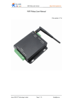
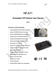
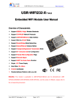
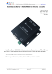
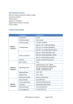
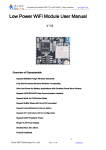
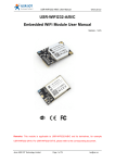
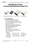
1
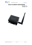
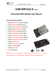
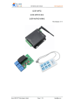
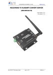
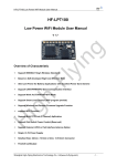
WIFI relay board user manual www.tcp232.net WIFI Relay Board User Manual File version: V1.0 Jinan USR IOT Technology Limited Page 1 / 16 [email protected] WIFI relay board user manual www.tcp232.net 1. Wifi relay board introduction 1. Product introduction 1.1 Features: WIFI interface, via WIFI connection for network control. Ethernet interface, can through the general network cable connection way to control. 5 channel large current output, 2 channel optocoupler input Unique AP+STA working mode, can work as AP when join into router. This allows the module accept local mobile terminal(cell phones, tablet PC) control as AP, when join in router to connect outer net. Unique dual TCP connect control, corresponding with above trait, local as TCP server accept client control, when connect to remote server as TCP client Supply core module detailed information, application program demo, support customized app(IOS, Android) 1.2 Electric parameter: Working voltage: 12 v working current: 100 ma working temperature: - 25 ~ 75 ° C storage temperature: -40 ~ 85 ° C storage humidity: 5% ~ 95% RH 1.3 Packing list: Wifi relay board * 1 12v power adapter * 1 User guide cd * 1 2. Using instruction Relay state when power on: 1&2 disconnected, 3 connect when power on, flicker when start on, then disconnect, 4&5 connect when power on Five channel output is the relay contact Two channel input is 0 ~ 5 v level signal input. Jinan USR IOT Technology Limited Page 2 / 16 [email protected] WIFI relay board user manual www.tcp232.net As shown in figure, the left for OUT1 ~ OUT5 five channel relay output: each channel has two terminals (example: OUT1 has two terminals, namely OUT11 and OUT12, other terminal, analogy OUT21 and OUT22, etc.), regardless of polarity, contact output. The right is IN1 ~ IN2 two channel level signal input Jinan USR IOT Technology Limited Page 3 / 16 [email protected] WIFI relay board user manual www.tcp232.net For example: relay board control filament lamp Jinan USR IOT Technology Limited Page 4 / 16 [email protected] WIFI relay board user manual www.tcp232.net 2.1 Android cell phone control Install USR-WIFI232-IO.APK in your cell phone, you can get a new folder. Open your phone wifi function, find and join USR-WIFI232-IO network. Open relay board software on android cell phone, picture as below: As WIFI module factory default TCP SERVER mode, port number is 8899, so android mobile phone IP port number should also be 10.10.100.254, 8899 and click the red “X” Jinan USR IOT Technology Limited Page 5 / 16 [email protected] WIFI relay board user manual www.tcp232.net Shows green “√” ok now. 2.2 IOS system control 1. Open APP Store, type in “USR” to get IOS control software, as follows: Jinan USR IOT Technology Limited Page 6 / 16 [email protected] WIFI relay board user manual www.tcp232.net 2. Directly click and download the software, an open it: Jinan USR IOT Technology Limited Page 7 / 16 [email protected] WIFI relay board user manual www.tcp232.net 3. Open this file on Iphone, because WIFI relay board core module default factory set is TCP SERVER mode, IP is the 10.10.100.254, so the corresponding files should be set it IP same as WIFI module SERVER address (10.10.100.254), port number 8899, click connect, now you can use IPHONE to remote control the WIFI relay board. As below: 2.3 Computer control Open software , windows as follows: Jinan USR IOT Technology Limited Page 8 / 16 [email protected] WIFI relay board user manual www.tcp232.net Then click Search, get default USR-WIFI232-IO, IP 10.10.100.254, PORT 8899, click open, then get information on the right, click the circle to connect, then you can control the device. 2.4 Remote server control In the picture, USR-WIFI232-X as STA, connect to Internet via gateway. Module as TCP Client, connect with the server on the Internet. This application can send data that collected by users’ device to server to manage and storage. Also the sever can command to control users’ devices 3. Connection instruction 3.1 application block diagram 3.1.1 WIFI-IO as AP application All info of Chapter 2 is for module as AP application 3.1.2 WIFI-IO as STA application Jinan USR IOT Technology Limited Page 9 / 16 [email protected] WIFI relay board user manual www.tcp232.net Log in module default IP address 10.10.100.254 to configuration page, set module as Station mode, click “apply” Then choose STA interface setting, see below page: Click Search button to find and choose networks, then it will input security mode and SSID automatically, you just need input password: Jinan USR IOT Technology Limited Page 10 / 16 [email protected] WIFI relay board user manual www.tcp232.net Don’t forget “Apply” after each step. Then choose device management page and restart the module. 3.2 AP+STA and dual TCP periodic line instruction 3.2.1 AP+STA wireless network USR-WIFI232-X module, V4.x version software support AP+STA. That is to say, the module support an AP interface and a STA interface at the same time. Shown as follows: In the picture, the module open AP+STA function, module STA interface can be connected to a router, and through the TCP connection to connect to the network server. At the same Jinan USR IOT Technology Limited Page 11 / 16 [email protected] WIFI relay board user manual www.tcp232.net time, the AP interface of module is available, cell phone /PAD, etc can connect to the AP interface (through the TCPB connection), control the serial port equipment or set up the module. through the AP+STA function, it is convenient to use cell phone, PAD, and other hands holding equipments to monitor the user equipments, instead of changing the original network settings. through the AP+STA function, can be very convenient to set up our module, solve the problem that module in STA mode only can be set by serial port previously. AP+STA function settings AP+STA function need serial port command to use AT+FAPSTA=on, to use AP+STA function Then when set module as AP mode, AP interface remain valid 3.2.2 TCPB function USR-WIFI232-X module, V4.x version support 2 TCP function, that is support two networking at the same time. The second network connection named as TCPB. The TCPB can only be as TCP Client, and set by AT command, don’t support web configuration. Commands as follows: AT+TCPB=on, set TCPB function AT+TCPPTB=<port>, set TCPB port number AT+TCPADDB=<IP or realm name>, set TCPB server address AT+TCPTOB=<time>, set TCPB timeout AT+TCPLKB, check if TCPB is connected Detailed information, please reference to AT instructions of “USR-WIFI232-X” When use TCPB function, two network interface working mode is similar with the above TCP connection. That is, no matter from which network interface the data sent from, they will be forwarded to serial ports, and data will be copied into multiple copies to each network interface. 3.3 Hardware connection Jinan USR IOT Technology Limited Page 12 / 16 [email protected] WIFI relay board user manual www.tcp232.net <instruction> 1. nRST: module reset signal, input. Low level effectively, module internal 100k resistance up connect to 3.3V. When module power on or in malfunction, 300ms low lever input will reset the module. 2. nReady: start completed signal, output. Module internal 4.7K up connect to 3.3V, after module normally start on, output low level (or heartbeat signal), can be used to judge whether the module ready. 3. nLink: module WIFI connection indication, output. Module internal 4.7 K resistance 上 拉 to 3.3V. When the module connected to AP or other wifi connected to the module, output 低 level, can be used to judge whether the module in network state. 4. nReload: can be connected to external button or configuration pin, when the button is pressed, the pin pull to low level, 3 seconds after let go, Module factory default after restart. This pin should be in module external and resistance (4.7 K ~ 10 K ohm) pull, if don't want to use This function, can use command AT + FRLDEN = off forbidden. 5. UART_TXD/RXD: serial port transmit/receive data signal 4. Communication protocol and secondary development 4.1 Communication protocol USR-WIFI232-X module, V4.x version support two GPIO mode. In GPIO-1 mode, UART four pin definition is GPIO, other signs such as nReady, nLink, nReload definition is constant. In GPIO-2 mode, UART pins and three sign pins are all GPIO. So, GPIO mode does not support serial port. When module working in GPIO mode, PC or other network devices can connect with Jinan USR IOT Technology Limited Page 13 / 16 [email protected] WIFI relay board user manual www.tcp232.net module (TCP/UDP) through the wifi, then control GPIO or read GPIO state through commands. Commands as follows: GPIO n IN: set GPIOn as input, receive GPIO OK or GPIO NOK GPIO n OUT 0: set GPIOn as output low level, receive command OK or NOK GPIO n OUT 1: set GPIOn as output high level, receive command OK or NOK GPIO n SW: set GPIOn as output and change the previous high and low level status, receive GPIO OK or NOK GPIO n PWM m1 m2: set GPIOn output a high and low change level, m1 is high level time, m2 is low level time(time unit ms, min 10 ms), receive GPIO OK or GPIO NOK GPIO n GET: read GPIOn status, receive I0, I1, O0, O1 respectively means input low, input high, output low, output high Notice: n can be 3,4,5,6,8,9,10, correspond with module pins. The GPIO4,10 can only be input, GPIO3 be output only. GPIO READ receive the current state of all IO, representation method the same as GPIO n GET. For example, I1I1I0I0I0I0O1, I means input, O means output. 0 means low, 1 means high 4 and 10, these two pins take the reverse. Read 1, acturely 0, read 0, acturely 1. High means relay connect, Low means relay disconnect. 4.2 Secondary development resources Our company provide the corresponding programming example, welcome to ask for when make order. 4.3 Customization development service Our company can customize according to the user's preferences as factory default configuration, this will greatly reduce the user's production module configuration time. At the same time, if the users need each module setting different parameters or to batch configuration module, we can provide batch configuration tool to improve the users’ configuration efficiency. Please contact our technical staff to obtain further batch configuration support. Jinan USR IOT Technology Limited Page 14 / 16 [email protected] WIFI relay board user manual www.tcp232.net Appendix A: Version updates V1.3 (time Jun 4, 2013) Firmware V4.02.08.25 added the control of each relay when start up, add two commands at+iodefault=on/off/normal (on: all relay output is connect when start up off: all relay output is disconnect when start up normal: normal status, 1,2 connect; 3,4,5 disconnect) at+iocontrol=on/off (on: open this function, off: disable this function) The two inputs control five outputs all on or all off (pin 10 all connect, pin 4 all disconnect, testing form is non-self locking key) Note: If you use new version to upgrade by yourself, you have to send these commands after module upgraded successfully AT+FASSID=USR-WIFI-IO AT+WRMID=USR-WIFI-IO AT+FAPSTA=on AT+FEPHY=on AT+RELD AT+TMODE=GPIO2 AT+Z Jinan USR IOT Technology Limited Page 15 / 16 [email protected] WIFI relay board user manual www.tcp232.net 5. Contact Company: Jinan USR IOT Technology Limited Address: 1-523, Huizhan Guoji Cheng, Gaoxin Qu, Jinan, Shandong, China Tel: 86-531-55507297 86-531-88826739-803 Web: www.tcp232.net Email: [email protected] Jinan USR IOT Technology Limited Page 16 / 16 [email protected]