1
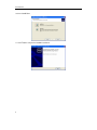
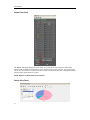
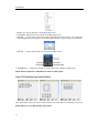
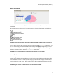
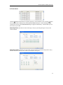
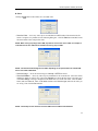
Remote Operation Software (DX-PC4U)
Table of Contents
Chapter 1 ─ Overview ............................................................................. 1
1.1 In This Manual .............................................................................. 1
1.2 DX-PC4U Features....................................................................... 1
1.3 Product Information ...................................................................... 1
Chapter 2 ─ Installation ........................................................................... 3
Chapter 3 ─ Configuration ....................................................................... 7
3.1
3.2
3.3
3.4
Screen .......................................................................................... 7
Panel............................................................................................. 8
Menu........................................................................................... 15
Toolbar........................................................................................ 26
Chapter 4 ─ Operation........................................................................... 27
4.1
4.2
4.3
4.4
Live Monitoring ........................................................................... 27
Playback and Search.................................................................. 30
Panic Recording ......................................................................... 36
Status View................................................................................. 36
Appendix A ─ Reviewing Video Clips .................................................... 39
Appendix B ─ DVR Name Service (DVRNS)......................................... 44
Appendix C ─ Map Editor ...................................................................... 45
Appendix D ─ AVI Converter ................................................................. 52
i
User’s Manual
ii
Remote Operation Software (DX-PC4U)
Chapter 1 ─ Overview
1.1 In This Manual
This manual describes installation and operation of DX-PC4U (Remote Operation Software), which is
designed to be used with remote digital video recorders (DVRs)
1.2 DX-PC4U Features
DX-PC4U program is an integrated software program that controls system management, video
monitoring, video recording and image playback of multiple remote DVRs. DX-PC4U offers the
following features:
y
y
y
y
y
y
y
y
y
Checks and reports status of remote DVRs
Notification of events detected at remote sites
Remote monitoring of live camera images
Panic recording of monitored images
Time-lapse and event search of recorded images
Remote software upgrades and system programming
View system and event log information of remote DVRs
Remote monitoring of multiple remote sites using 3D maps
Connect up to 16 remote sites at a time
1.3 Product Information
Package Components
y
y
User’s Manual (this document)
Installation CD
System Requirements
y
y
y
y
Operating System: Microsoft Windows XP or later
CPU: Intel Pentium IV (Celeron) 2.4GHz or faster
RAM: 512MB or higher
VGA: AGP, Video RAM 8MB or higher (1024x768, 24bpp or higher)
1
User’s Manual
2
Remote Operation Software (DX-PC4U)
Chapter 2 ─ Installation
CAUTION: If an older version of DX-PC4U software is installed on your computer, you
should uninstall the older version first.
NOTE: In the Start menu in Windows, go to Control Panel. Double click the Power Options to
evoke the Management Properties dialog box. Under the Power Schemes tab, set both Turn off
monitor and Turn off hard disks to Never.
1. Insert the installation CD.
2. Run the RASplus_Setup.exe file.
3. When the following dialog box appears, click Next.
4. Click Install.
3
User’s Manual
5. Set the language option by selecting either Select language when starting RASplus or Always
start RASplus using the language below. If you select Always start RASplus using the
language below, select the desired startup language from the list of available languages and then
click OK.
NOTE: To properly display the selected language, your PC’s operating system should be set to
support the selected language.
NOTE: In order to change RASplus’ language after selecting the Always start RASplus using the
language below option, the RASplus software should be reinstalled.
6. When the following dialog box appears after finishing the RASplus installation, select MSXML
application and click Finish. Installing the MSXML is required for RASplus to initiate.
4
Remote Operation Software (DX-PC4U)
7. Click Next.
8. Select I accept the terms in the License Agreement, and click Next.
9. Enter User Name and Organization, and click Next.
5
User’s Manual
10. Select Install Now.
11. Click Finish to complete the MSXML installation.
6
Remote Operation Software (DX-PC4U)
Chapter 3 ─ Configuration
After installing the DX-PC4U software, you will find the DX-PC4U shortcut icon
on the desktop.
Run the DX-PC4U program by double clicking the icon. The DX-PC4U program consists of the screen,
12 docking panels, menu and toolbar.
3.1 Screen
The Screen displays images from selected cameras in the live monitoring or playback modes. DX-PC4U
provides various multi-screen formats; single-screen, quad, 1+7, 3x3, 4x4, 5x5, 1+32, 6x6, 7x7, 8x8 and
full-screen.
7
User’s Manual
3.2 Panel
DX-PC4U has many powerful tools that can be used to streamline your work. Most of the tools are
located on 12 docking panels that can be placed on the screen where they are most convenient. You can
keep your screen free of clutter by displaying only the panels you use most frequently.
Clicking the
icon in the upper right corner of a panel enables the auto-hide feature. Tabs for
auto-hidden panels are displayed on the side of the screen. Scrolling over an auto-hidden panel tab will
cause the panel to "fly" out. You can cause the panel to lock back into its original display position by
clicking the
icon. Clicking the
icon hides the panel without a tab. Hidden panels can be displayed
by selecting them from the drop-down menus.
Panels can be resized, moved and combined with other panels creating a workspace that fits your needs.
To resize a panel, scroll the cursor over the edge of the panel until the cursor changes to
or . Then
click the left mouse button and drag the panel border to enlarge or reduce its size.
To move a panel to a different position on the screen, scroll the cursor over the title bar of a panel that has
not been auto-hidden until it changes to . Once you click and drag, position arrows will display on the
screen.
The four position arrows along the outer edges allow you to place the panel along the given edge
independent of the other panels. When you drag the panel over a position arrow, a transparent blue box
will display showing the new panel position. If you are satisfied with the position, release the left mouse
button and the panel will move to its new position.
You can also move a panel so that it is associated with another panel. To do this, drag the panel over the
panel you want it associated with, and the icon with four position arrows will center over that panel.
Scrolling the cursor over the icon arrows will cause a transparent blue box to display where the panel will
be located. If you are satisfied with the position, release the left mouse button and the panel moves to its
new position.
It is possible to combine panels so that they take up less space on the screen. Combined panels have a row
of tabs across the bottom. Clicking a tab brings that panel to the foreground.
To combine panels, move the cursor to the title bar of the panel you want to move. Click and drag the
panel onto the panel you want to combine it with. If the panels can be combined, the four-position arrow
icon will have a tab symbol in the center. Drag the cursor over the tab symbol , and a new tab appears
on the panel. Release the mouse button and the panels will now be combined.
The layout possibilities are virtually unlimited. With a little experimentation you will be able to lay out
the screen so that it best meets your workflow.
8
Remote Operation Software (DX-PC4U)
Remote Sites Panel
The Remote Sites Panel displays a list of remote sites registered during DX-PC4U System setup and a
list of installed cameras at the remote sites. Entering the site name in the query box and clicking the
icon allow you to find the remote site easily in the Remote Sites list. To connect to a remote site, select
the site or camera you want to connect to from the list and then drag and drop it in the desired position on
the screen or the Status View panel. The screen displays images from selected cameras, and the Status
View panel displays the system status information of the connected remote site. Connecting to the Status
View panel can also be done by selecting Connect Status View from the popup menu displayed by
clicking the right mouse button after selecting the site from the list. This popup menu initiates the remote
menu including Remote Setup, Remote System Log, and Remote Event Log. Refer to 3.3 Menu –
Remote Menu for more details.
Favorite Sites Panel
The Favorite Sites panel displays the list of Favorite sites registered during DX-PC4U System setup.
Selecting the Favorite site you want to connect to from the list and then dragging and dropping it in the
desired position on the screen connects all remote sites registered in the Favorite site automatically.
9
User’s Manual
Status View Panel
The Status View panel displays the event, alarm out, system check, object detection, video blind
detection and recording status information of the connected remote site in real-time. To connect to the
remote site, select the site or camera you want to connect to from the Remote Site or Map panel and then
drag and drop it in the Status View panel.
NOTE: Refer to 4.4 Status View for more details.
Search View Panel
10
Remote Operation Software (DX-PC4U)
The Search View panel allows time-lapse or event searching of recoded data on the remote DVR.
NOTE: Refer to 4.2 Playback and Search for more details.
Map Panel
The Map panel allows efficient monitoring of the remote sites by displaying a three-dimensional map of
the selectable site. Click the right mouse button on the map panel to select the map image file (.rmp) you
want to monitor from the list. When the selected map is linked with sub-maps, clicking the linked image
moves to the sub-map. To connect to the remote site, select the device you want to connect to from the
Map panel and then drag and drop it in the desired position on the screen or the Status View panel. Also,
placing the mouse cursor on the device on the map displays the device status. When the device detects
any event or the device is not working properly, the following status icons appear (maximum of 4).
Unplugged
Switch off
Irregular
Video Loss
Motion
Alarm In
Alarm Out
NOTE: The status of devices is displayed as Irregular based on to the settings in System Check
and as Video Loss, Motion, Alarm In and/or Alarm Out according to the event detection settings on
the remote DVR.
The Map panel pops up another screen when alarm-in, motion or video loss events are detected or when
you click the device icon according to the Map Editor settings. Refer to Appendix C- Map Editor –
Device Setting section for more details of popup function. Change the popup screen location by clicking
the left mouse button on the screen and dragging it to where you want it located. Clicking the right mouse
button on the popup screen displays the following popup menu.
11
User’s Manual
y x0.25 to x2: Sets the desired size of the Map popup screen.
y Full Screen: Enters the full-screen mode of the Map popup screen.
y User Set…: Sets the mode of the current popup screens displayed on the monitor. For example, the
monitor displays the current popup screen with enough frames for 16 cameras when you select 4x4.
y PTZ Set…: Controls pan, tilt and zoom of the selected PTZ camera.
y Transparency…: Adjusts the transparency of the popup screen. (Windows 2000 or later).
NOTE: Refer to Appendix C – Map Editor for details on editing maps.
Color, PTZ and Alarm Out Control Panels
Three panels allow color control, PTZ control and alarm out control while live monitoring a remote site.
NOTE: Refer to 4.1 Live Monitoring for more details.
12
Remote Operation Software (DX-PC4U)
Image Processing Panel
The Image Processing panel allows enhancing played back images.
NOTE: Refer to 4.2 Playback and Search for more details.
Emergency Event View Panel
The Emergency Event View panel displays a list of events (preset for notification at the remote site)
that were called from individual remote sites (LAN connection only).
Watch Event View Panel
The Watch Event View panel displays events detected at individual remote sites while DX-PC4U is in
the live monitoring mode. The description of event icons is as follows:
13
User’s Manual
Normal Event
Alarm In On
Alarm In Off
Motion Detection
Object Detection
Video Loss
Video Blind
Text In
Alarm In Bad
Recorder Bad
Disk S.M.A.R.T.
Disk Bad
Disk Full
Disk Temperature
Panic Recording On
Panic Recording Off
Report View Panel
The Report View panel displays the system status information of remote sites. DX-PC4U checks the
remote site and reports system status. Report Setup must be configured during DX-PC4U System setup
for this feature to function. Refer to 3.3 Menu – System Menu for more details.
NOTE: Some report options may not be supported, depending on the specifications of the remote
DVR.
14
Remote Operation Software (DX-PC4U)
3.3 Menu
System Menu
X Setup
The Setup screen allows setting up the system operation and remote site configuration.
15
User’s Manual
System 1: Set up the date/time format for DX-PC4U, display option, and panic recording function.
y
y
Date/Time Format: Set the date/time format.
Display Option: Set up the screen display, drag & drop popup option, display acceleration and OSD.
– Screen Option: Select Watch Screen to use the screen for live monitoring only, Search Screen to
use the screen for search only, or Watch and Search Screen to use the screen for both live
monitoring and searching
– Drag & Drop Popup Option: Select which mouse button will be used when displaying popup menu
screens from Use Left Mouse Button, Use Right Mouse Button or both (Watch and Search
Screen mode only).
– Display Acceleration: Select None (Not using the display acceleration), Normal (Using the
DirectX display acceleration) or Full (Using the DirectX Video Memory display acceleration).
– OSD Setup…: Select options (Title, Time Info, Date Info, Text-In and Overlay Text-In Data) to
display on the screen.
NOTE: If the image cannot be displayed properly because of your PC’s specifications, lower the
display option level.
y
Recording Setup: Set up the Use (On or Off) of the panic recording function and overwriting option
of the recording folder (On or Off). When using the panic recording function and overwriting option,
DX-PC4U continues recording when the hard disk drive is full by overwriting the oldest video.
Designate a recording folder path and set the recording folder size from 640MB to 2048MB. Capacity
shows the remaining space of the recording folder.
NOTE: The recording folder size cannot be changed once it has been set. Designate another
recording folder path if you want to expand the recording space.
16
Remote Operation Software (DX-PC4U)
System 2: Set up the modem connection information for remote access, system password, network
option, report function and DVRNS server.
y
y
y
Dial-up Network: Select Use modem if you want to use a modem for remote access.
Security Options: Designate whether password confirmation is required Before setup, Before
startup, or Before shutdown of DX-PC4U. Click the Change button to change the password.
Network Option: Set up the IP port number (from 8000 to 12000) that is used for network connection
when receiving a callback message from a remote site, and the upgrade port number that is used for
upgrading the PC-based DVR.
NOTE: The IP port and upgrade port numbers you enter should match the values set during the
network setup of the remote DVR.
y
y
Report Setup: Set up the Use (On or Off) and check intervals (from 1 to 24 hours) of the report
function. When using the report function, DX-PC4U checks on the remote site based on the
user-defined interval and reports system status.
DVR Name Service: Set up the IP address and port number (from 10000 to 12000) of the DVRNS
(DVR Name Service) server. The IP address and port number you enter should match the values set
during the DVRNS setup of the remote DVR you want to connect to.
NOTE: The DVRNS server cannot be configured when using modem connections. Refer to
Appendix B for more details on DVR Name Service.
Remote Site: Configures the connection list for remote access.
17
User’s Manual
y
Add: Click the Add button and enter the information about the remote site you want to add.
– Reference Group: The site should be assigned to a Reference Group for effective management of
multiple remote sites. Click the Add button to create a new reference group.
– Remote Site Setup: Enter a site name and the IP address of the remote site (modem telephone
number for dial-up connections), acquired from your network administrator. Click the Port… button
to set up the IP port number of each program. The IP port number should match the value set during
the network setup of the remote DVR. If the remote DVR version does not allow you to set the IP
port numbers, use the following values: “8200” for Admin, “8016” for Watch, “10019” for
Search, and “8116” for Audio. Select the number of cameras of the remote site. For example,
selecting “8” from the list when registering the 16-channel DVR displays video of the first 8 channels
on the screen.
NOTE: When using DVRNS server, place a checkmark in the Use DVRNS (DVR Name Service) box,
and enter the site name and DVR name of the remote site in the IP address box. The DVR name
you enter should match the DVR name set during the DVRNS setup of the remote DVR.
– Login Setup: Enter the user ID and password of the remote site to be accessed. If you have entered
a user ID and a password, the site will be connected automatically without a dialog box requesting a
password. Select No Password for remote systems that do not require a password (e.g., guest
login).
NOTE: Up to 32 characters may be used for the site names, telephone numbers and user IDs, and
up to 10 characters may be used for passwords.
y
y
y
y
Change: Select the group or site you want to change and click the Change button, or double click the
group or the site to change. Then, edit the site information.
Remove: Select the group or site you want to remove and click the Remove button.
List All: Displays all registered remote sites.
Find: Enter the group name or site name to search for and click the Find button to display the matching
groups or sites in the list.
18
Remote Operation Software (DX-PC4U)
Favorite Site: The Favorite Site is a user-defined connection list that combines more than one remote
site, so multiple sites can be monitored at the same time with a single connection. Add a new Favorite
Site and define it by dragging and dropping sites and/or cameras to the Favorites map. Up to 64 cameras
can be monitored at a time when each camera is assigned to its own position on the Favorites map.
y
y
y
y
y
y
Site Name: Select a registered Favorite site from the drop-down list.
ADD: Adds a new Favorite site.
Change: Select the Favorite site to change from the Site Name list and click the Change button. Then
change the site name.
Remove: Select the Favorite site to remove from the Site Name list and click the Remove button.
Remove Selected Camera: Removes selected cameras from the Favorites map. Cameras can also be
removed by clicking the right mouse button after selecting the camera.
Remove All Cameras: Removes all cameras from the Favorites map.
NOTE: Cameras can be selected by clicking the left mouse button on the camera in the Favorites
map. Selected cameras will be outlined in red. Clicking the left mouse button on the camera while
holding the Ctrl key toggles camera selection On and Off. Multiple cameras can be selected by
clicking the left mouse button while holding the Shift key.
NOTE: “[W]” (Watch Screen) and “[S]” (Search Screen) displayed to the left of the camera number
indicates the display option of each camera. The display option can be selected when registering
a Favorite site. Selecting the remote site from the Group List and dragging and dropping it to the
Favorites map using the right mouse button displays the text menu screen. Select the desired
displays option between Watch Screen and Search screen. If you do not select the display option,
Watch Screen display will be assigned to all cameras of the registered Favorite site by default.
19
User’s Manual
button on the toolbar will save the current screen layout of the Watch
NOTE: Clicking the
screen or Search screen directly to the Favorite site.
NOTE: The Favorite Site list does not work with modem connections.
Sequence Site: Configure the sequence site. DX-PC4U connects to the registered sites sequentially
allowing connection to more than one remote site.
y
y
y
y
y
Sequence dwell time: Adjust sequence intervals (from 5 second to 1 hour) for each connection.
Add: Select the site to add from the Group List and click the Add button.
Add All: Adds all sites in the Group List to the Auto Sequencing list.
Remove: Select the site to remove from the Auto Sequencing list and click the Remove button.
Remove All: Removes all sites in the Auto Sequencing list.
NOTE: The Auto Sequencing list is not valid with modem connections.
20
Remote Operation Software (DX-PC4U)
X Batch Job Setup
Multiple remote sites can be upgraded or set up using the Batch Job Setup screen.
Upgrade: Sets up the remote upgrade job for remote sites. First, select the remote sites to upgrade from
the Group List, and add them to the Upgrade Sites list by clicking the Add button. Then, click the
Upgrade Now button to initiate the remote upgrade job for registered Upgrade Sites.
y
y
y
y
y
Add: Select the site to add from the Group List and click the Add button.
Add All: Adds all sites in the Group List to the Upgrade Sites list.
Remove: Select the site to remove from the Upgrade Sites list and click the Remove button.
Remove All: Removes all sites in the Upgrade Sites list.
Upgrade Now: Upgrades the software on the Upgrade Sites.
NOTE: When upgrading a PC-based DVR, select PC Based DVR and then select the desired
upgrade folder.
21
User’s Manual
Setup: Sets up the remote setup job for remote sites. First, select the remote sites to set up from the
Group List, and add them to the Setup Sites list by clicking the Add button. Then, click the Setup Now
button to initiate the remote setup job for Setup Sites.
y
y
y
Add: Select the site to add from the Group List and click the Add button.
Remove All: Removes all the sites in the Setup Sites list.
Setup Now: Performs the setup on the Setup Sites.
NOTE: Batch job setup of remote sites is NOT supported for the PC-based DVRs.
X Disconnect
Disconnects all current connections. Disconnection can also be performed by clicking the
the toolbar.
button on
X Log
Log displays the system log and batch job log information of DX-PC4U, and the log information of
emergency events called in from remote sites. It displays up to 5,000 log entries.
22
Remote Operation Software (DX-PC4U)
File
y
y
y
y
Log File Open: Opens the saved log file.
Save As…: Saves the log information as a text file.
Print: Prints the log information.
Exit: Closes the Log dialog box.
View
y
y
y
y
y
Show All Logs: Displays all log entries.
Show Filtering Log: Displays log entries within the parameters set by the filter
options. Select the filter options and set the search starting date/time and ending
date/time.
New Log First: Displays the newest log first.
Old Log First: Displays the oldest log first.
Row Add or Remove: Adds or removes columns in the Log dialog box.
23
User’s Manual
X Exit
Disconnects all current connections and exits DX-PC4U program.
View Menu
Displays or closes the toolbar and panels.
Remote Menu
NOTE: The Remote menu can also be activated by clicking the right mouse button after selecting
the remote site on the Remote Sites panel.
X Remote Setup
Remote Setup can be used to change the setup of a remote DVR. Select the remote site on the Remote
Sites panel, initiate the Remote Setup menu, and the setup screen displays.
NOTE: Refer to the user manual for the remote DVR for more details on system setup.
X Remote System Log/Remote Event Log
These selections display the system log and event log information of a remote DVR. Set the time range of
interest and click the Find button. The log entries within the time range displays in the list. 100 results
can be displayed in a single page. Click the Move buttons to display additional results.
24
Remote Operation Software (DX-PC4U)
y
y
y
y
y
y
y
From: Adjust the search starting date and time. When First is selected, it will search from the first
logged item.
To: Adjust the search ending date and time. When Last is selected, it will search to the last log.
Find: Displays remote log entries within the selected period.
Print...: Prints the log information.
Save...: Saves the log information as a text file.
Move Buttons: Moves to the first page ( ), previous page ( ), next page ( ) or last page ( ). You
can go directly to a log page by clicking the page number button.
Close: Closes the Log dialog box.
Image Menu
NOTE: The Image menu can also be accessed using the Image Processing panel controls and the
toolbar controls.
y
y
y
Image Processing: Allows the user to enhance images that are played back.
Save: Saves the current image as a bitmap or JPEG file.
Print: Prints the current image.
NOTE: Refer to 4.1 Live Monitoring and 4.2 Playback and Search for more details.
25
User’s Manual
Help Menu
The Help menu displays DX-PC4U version information.
3.4 Toolbar
The Toolbar allows convenient access to desired functions.
The controls on the toolbar perform functions as described below:
Disconnect
DX-PC4U Setup
Batch Job Setup
System Log
Emergency Event Log
Batch Job Log
Save Favorite Sites
Auto Sequence
Save
Print
Panic Recording
Play
Select the desired screen format using the layout toolbar. When changing the screen format, the selected
camera on the current screen will locate at the first cell of the layout to be changed. When in one of the
or button will move to the previous or next page. In other words,
multi-view formats, clicking the
when viewing Cameras 1 to 4 in the quad format, clicking the
button will display Cameras 61 to 64
and clicking the button will display Cameras 5 to 8.
26
Remote Operation Software (DX-PC4U)
Chapter 4 ─ Operation
4.1 Live Monitoring
DX-PC4U provides remote monitoring functions for viewing video images in real time from either a
single site or multiple sites. In addition, when events are detected at a remote site while in the live
monitoring mode, DX-PC4U displays the event information on the Watch Event View panel. In order to
perform live monitoring, the display option must be set to Watch Screen or Watch and Search
Screen during System setup.
To connect a remote site on the Watch screen, select the site or camera you want to connect to in the
Remote Site or Favorite Sites panel and then drag and drop it in the desired position on the screen. Click
the button on the toolbar or select Disconnect from the System drop-down menu to disconnect the
current connection.
NOTE: Some DVR models will only transmit images to a remote site while recording video.
NOTE: When selecting the displays option of Watch and Search Screen during System setup, the
remote site can also be set to connect using the right or left mouse buttons (This is user-defined
and must be set during System setup). Select Watch Screen to connect to the selected site on the
Watch screen when the following text menu screen appears.
Screen Format
DX-PC4U provides multiple screen layout options. The formats available are single-screen, quad, 1+7,
3x3, 4x4, 5x5, 1+32, 6x6, 7x7, 8x8 and full-screen. When in one of the multi-view formats, clicking the
or button will move to the previous or next page.
To view a specific image in the single-screen mode, move the cursor to that image and double click the
left mouse button. To return to the previous screen mode from the single-screen mode, double click the
left mouse button in the monitoring window.
Camera Title
The user can change the camera name displayed on the screen. Select a camera on the screen and click
the right mouse button. Selecting Change Camera Title... in the text menu screen displays the
following Camera Title box.
27
User’s Manual
Enter the camera name and click the OK button. Leaving the Camera Title blank causes the camera name
set up on the remote site to display.
NOTE: Changing the camera title is available in the both Watch and Search screens, and it does
not affect the camera name set up on the remote site.
Audio Communication
DX-PC4U supports audio communication between the DX-PC4U system and the DVR location equipped
with two-way audio. If you want to enable audio communication with the remote site you want, select
any camera of the remote site on the screen and click the right mouse button. Selecting Enable Audio...
in the text menu screen displays the following Audio Control box.
If you want to send audio to the selected remote site, place a checkmark in the Send box and talk into the
microphone. If you want to monitor live audio from the selected remote site through the attached speaker,
place a checkmark in the Receive box. Placing a checkmark in both Send and Receive boxes allows
for two-way communication. Clicking the Close button disables audio communication.
If the remote DVR sets an audio channel to monitor to be selected from the DX-PC4U system, placing a
checkmark in the Receive box displays the following Select Audio Channel dialog box appears.
Select an audio channel to monitor and click the OK button.
NOTE: Audio communication may not be supported and depends on the specifications of the
remote DVR.
Sequence Monitoring
Clicking the button on the toolbar connects to the registered sites sequentially allowing connection to
more than one remote site and displays images from selected cameras. For sequence monitoring to
function, the sequence sites should be registered during System setup. Refer to 3.3 Menu – System Menu
for details on configuring the sequence site.
NOTE: While in the sequence monitoring mode, you cannot manually connect to sites by
dragging and dropping with the mouse.
28
Remote Operation Software (DX-PC4U)
Additional Functions
X Color Control
Adjust the brightness, contrast, saturation and hue for each camera by clicking the target icons on the
Color Control panel. Clicking the
icon cancels the image processing operation and reloads the
original image. Only the administrator can adjust the image from a remote site.
NOTE: It is important that cameras are properly adjusted. These adjustments cannot make up for
improperly adjusted cameras when the images are recorded.
X PTZ Control
Select a PTZ camera at the remote site, and control pan, tilt and zoom. Only the administrator can control
PTZ from a remote site.
NOTE: PTZ control using the mouse is supported. Click the left mouse button on the image and
move that image to the direction you want to by dragging the mouse. Roll the mouse wheel to
zoom in or out.
X Alarm Out Control
Control alarm out devices on the remote DVRs by clicking the ON or OFF buttons. Only the
administrator can control an alarm out from a remote site.
NOTE: Not all DVRs support remote control of color, PTZ and alarm out. Refer to your DVR’s
documentation.
29
User’s Manual
X Save
Clicking the button on the toolbar saves the image currently displayed on the screen as a bitmap or
JPEG file. By placing a checkmark in the box beside Include Image Info., text information about the
site will be included when saving the image.
X Print
Clicking the button on the toolbar prints the image currently displayed on the screen on a printer
connected to your computer. By placing a checkmark in the box beside Include Image Info., text
information about the site will be included when printing the image.
4.2 Playback and Search
DX-PC4U allows you to play back and search recorded images on remote DVRs. It also provides
additional functions including zoom, various image enhancements, image saving and image printing. To
use remote playback and search functions, the display option must be set to of Search Screen or Watch
and Search Screen during System setup.
To connect a remote site on the Search screen, select the site or camera you want to connect to in the
Remote Site or Favorite Sites panel and then drag and drop it in the desired position on the screen. The
remote site connection on the Search screen will automatically be disconnected if there is no activity for a
specified amount of time. Click the button on the toolbar or select Disconnect from the System
drop-down menu to disconnect the current connection manually.
NOTE: Connecting to a Favorite site will be available if the Search Screen display option was set
up to connect to selected Favorite sites. Refer to 3.3 Menu – System Menu for more details on
Favorite Site setup.
NOTE: When selecting the display option of Watch and Search Screen during System setup, the
remote site can be also be set to connect using the right or left mouse buttons (This is
user-defined and must be set during System setup). Select Search Screen to connect to the
selected site on the Search screen when the following text menu screen appears.
It is possible to display cameras in both the Watch Screen mode (live view) and Search Screen mode at
the same time. For example, you can connect to a remote DVR site with nine cameras. Drag and drop the
site into the first frame on the viewing screen and select Watch Screen. Live video will display in the
first nine frames on the screen. Then, drag and drop the site into the 10th frame on the viewing screen and
select Search Screen. You will be able to view any video recorded on the remote DVR in frames 10
through 18.
30
Remote Operation Software (DX-PC4U)
Search View Panel
The Search View panel consists of playback and search controls, time-lapse search table, and event
search table.
The playback buttons on the Search View panel perform the following functions as described below:
Go to the First Image
Fast Backward Play
Go to the Previous Image
Stop
Play
Go to the Next Image
Fast Forward Play
Go to the Last Image
NOTE: The speed of fast forward depends on network bandwidth and the number of images per
second recorded.
You can enlarge a specific part of the image up to five times using the
control slider. The
user can electronically pan and tilt within the enlarged image by dragging the image using the mouse.
Click the left mouse button on the enlarged image and drag to move its position. You can change the
brightness of the current image using the
control slider.
NOTE: Zoom in/out and brightness control work only while in the pause mode.
Search Mode
DX-PC4U supports two search modes: time-lapse mode and event mode. The time-lapse search mode
searches for recorded data by time and then plays back images found within the time parameters. The
event search mode searches for event log entries using specific conditions and plays back the images
associated with those event entries. These two modes have different panel configurations and search
methods.
NOTE: Using two search modes at the same time will NOT be available.
31
User’s Manual
X Time-Lapse Search
NOTE: The timetable chart of the time-lapse search panel will differ depending on the model of
remote DVR that is connected to DX-PC4U.
Click the
button on the Search View panel to enter the time-lapse search mode. Selecting a date from
the calendar initiates the time-lapse search. The dates for which recorded images are available are
enabled. When first entering the time-lapse search, the latest date with recorded images will be selected
(highlighted) in the calendar. Click the
(Reload) button to reload the date information. Recorded
information available from the selected date will be displayed on the timetable chart.
The recorded data are displayed by time in one-hour segments. A green-highlighted segment indicates
the selected time that will be played back. Blue-highlighted segments indicate there is no recorded data
during that time, and pink-highlighted segments indicate there is recorded data during that time. Select a
specific hour by clicking the mouse on the desired hour segment. Video images will be played back
starting with the first image captured within the one-hour segment. When searching video recorded on
the PC-based DVR, the recorded data are displayed by time in one-minute segments and bar-shaped
segments indicate there is recorded date during that time.
To view an image at a specific time, click the
(Go To) button.
If the remote DVR’s time and date have been reset to a time that is earlier than some recorded video, it is
possible for the DVR to have more than one video segment in the same time range. Click the
(Segment) button and select the video segment you want to search. The active segment will be
highlighted with pink, and the inactive segment will be highlighted with gray on the timetable chart.
32
Remote Operation Software (DX-PC4U)
X Event Search
Click the
button on the Search View panel to enter the event search mode. First, click the
button,
and set up the search condition in the following Event Search dialog box. When loading the event
search for the first time, this Event Search dialog box appears automatically. Search modes by Event
and Camera are provided.
Search By Event: Searches for results of the target event(s) by selecting the target event(s) as the
search condition.
Search By Camera: Searches for event results of target camera(s) associated with optional event(s),
and also searches for more specific results by selecting the event type(s).
33
User’s Manual
NOTE: When First is selected for the search starting time, the search will be from the first
recorded data. When Last is selected for the search ending time, the search will be to the last
recorded data.
NOTE: The type of search methods in the Event Search dialog box can vary depending on the
specifications of the remote DVR.
Set up the search criteria for the event search in the Event Search dialog box. Select the search method
first, and then after setting the search period and the other conditions click the Find button. The results
(Query
will be displayed in the event list. A total of 100 results can be displayed at a time. Click the
Next) button to display the next results. If you select an event in the list, the recorded data associated
with that event will be displayed on the screen. The images may be played back using the playback
buttons.
NOTE: Event Search function is NOT supported for the PC-based DVRs.
Additional Functions
X Searching Data Source
Click the
y
y
button to set up the data source to be searched.
Search on Local: Searches recorded data on primary storage installed in the remote DVR.
Search on Archive: Searches archived data on backup storage installed in the remote DVR.
X Screen Format
DX-PC4U provides multiple screen layout for playback. The available formats are single-screen, quad,
1+7, 3x3, 4x4, 5x5, 1+32, 6x6, 7x7 and 8x8 and full-screen. When in one of the multi-view formats,
clicking the
or button will move to the previous or next page.
X Image Processing
The Image Processing panel allows enhancing played back images using processing controls.
Blurs the image.
Sharpens the image.
Equalizes the image.
Reduces the alias effect that occurs when using the zoom function.
Reloads the original image.
34
Remote Operation Software (DX-PC4U)
X Save
Clicking the
y
button on the toolbar saves recorded video.
Save As Video…: Saves any video clip of recorded data in an AVI (Audio Video Interleaved) file
format. Set up the save parameters in the following dialog box. Click the Start button and then set the
file name and the video compression codec.
NOTE: When saving clips larger than 1GB, clips will be saved in the unit of 1GB. For example, 3
individual files of each 1GB will be created when saving clips of 3GB.
NOTE: The Save As Video dialog box will differ depending on the specifications of remote DVR
that is connected to DX-PC4U.
y
y
Save As Image…: Saves the current image in a bitmap or JPEG file format.
Save As MiniBank…: Saves any video clip of recorded data as an executable file. Select the camera
number for which you want to save video in the Camera box, and set the time range you want to save
in the Save Range. Placing a checkmark in the Audio box saves audio with video. Click the Start
button, and select Save in. Enter a File name and then select Save as type (.exe) for the video you
are saving. Then click the Save button
NOTE: The backup file size must be less than 2GB because of Microsoft limitations.
35
User’s Manual
X Print
Clicking the button on the toolbar prints the image currently displayed on the screen on a printer
connected to your computer. By placing a checkmark in the box beside Include Image Info., text
information about the site will be included when printing the image.
4.3 Panic Recording
Clicking the
button on the toolbar starts panic recording of first 16 channels currently displayed on the
Watch screen. Clicking the button again stops panic recording. Clicking the
button on the toolbar
initiates the Record Player program and plays video saved in the recording folder designated during the
System setup. The Record Player GUI and its controls are almost identical to the Clip Player. Refer to
Appendix A – Reviewing Video Clips, Clip Player.
If you want to play back video saved in another recording folder, run the Record Player program first.
Move to the Start menu in Windows. Then, select RecordPlayer from the DX-PC4U options and select
the recoding folder path you want.
Recorded video can be saved in a bitmap or as an executable file using the save function of the Record
Player.
NOTE: Panic recording will be available only if you select Use Recording and it is set up in the
recording options during the System setup.
NOTE: The date and time displayed on the Record Player indicates when the recording was made
on DX-PC4U.
4.4 Status View
DX-PC4U provides a display of event, alarm out, system check and recording status information from the
connected remote site in real-time. To connect the remote site, select the site or camera you want to
connect to from the Remote Site or Emergency Event View panel and then drag and drop it in the Status
View panel. Or, you can select Connect Status from the popup menu displayed by clicking the right
mouse button after selecting the site from the Remote Site list.
36
Remote Operation Software (DX-PC4U)
Function Buttons
Disconnect: Disconnects the current connection on the Status View panel.
NOTE: If you want to connect to another site, disconnect from the currently connected system on
the Status View panel first by clicking the
button.
Remote Setup: Allows changing the setup of the remote DVR connected to the Status View panel.
NOTE: Refer to the manual for each applicable remote DVR for more details on system setup.
Remote System Log: Displays the system log information of the remote DVR connected to the
Status View panel.
Remote Event Log: Displays the event log information of the remote DVR connected to the Status
panel.
NOTE: Refer to 3.3 Menu – Remote Menu for more details on the Remote System Log and Remote
Event Log.
NOTE: When the remote site is not connected to the Status View panel, Remote Setup, Remote
System Log and Remote Event Log menus can be accessed by clicking the right mouse button
after selecting the remote site on the Remote Sites panel.
37
User’s Manual
Status Display Window
The Status Display Window displays the event, alarm out, system check and recording status
information of the remote system connected to the Status View panel in real-time.
y
Event: Displays events detected by the internal motion detector or by an external sensor. The status
display of event detection will continue during the preset dwell time of the event-driven recording.
Event Detection
No Event Detection
Event Off
y
(Motion Detection, Sensor)
Alarm Out: Displays status of the alarm-out signals.
Alarm Out
No Alarm Out
Alarm Out Off
y
System Check: Displays the function status of the camera, alarm, and recording of the remote DVR.
Normal
Irregular
System Check Off
(Camera, Alarm, Recording)
NOTE: Display of some System Check icons may not be supported and depends on the
specifications of the remote DVR.
y
Object Detection: Displays the status of object detection.
Object Detection
No Object Detection
Object Detection Off
y
Video Blind: Displays the status of video blind.
Video Blind
No Video Blind
Video Blind Off
NOTE: Display of Object Detection and Video Blind status may not be supported and depends on
the specifications of the remote DVR.
y
Record From/To: Displays the record period.
y
Status: Displays the recording, playback, archiving, clip-copy status.
On
Off
(Recording, Playback, Archive, Clip-Copy)
NOTE: Display of some Status icons may not be supported and depends on the specifications of
the remote DVR.
y
Version: Displays the system version information.
38
Remote Operation Software (DX-PC4U)
Appendix A ─ Reviewing Video Clips
You do not need to install any special software on you personal computer to review video saved as
MiniBank files. The backup file contains a Player program. Double-clicking the target file starts the
Player program.
NOTE: The Player GUI will differ depending on the model of the remote DVR that is connected to
DX-PC4U when reviewing the video saved as a MiniBank file.
MiniBank Player
NOTE: It is suggested that the computer used for the MiniBank Player program has at least a
800MHz Pentium III. If your CPU is slower than this, video clips recorded at maximum speed with
very high image quality will be played back slowly.
The Monitoring Screen displays the backed up images. Click the right mouse button on the image to
zoom in and click the right mouse button while holding the Ctrl key to zoom out. Scrolling the mouse
wheel up or down on the image also zooms in or out. Clicking the right mouse button on the image while
holding the Shift key switches the screen size. Click and hold the left mouse button and drag the image to
move its position.
Clicking the Quit button exits the Player program.
Click the Save button to save the current image in a bitmap file format on the local hard disk drive or
floppy disk.
Click the Print button to print the current image on the printer connected to your computer.
39
User’s Manual
The Backup File Information window displays information regarding the backup file. Location
displays the site description of the DVR where the backup was made. Record displays the time span of
the video backup file. Encryption displays whether the backup file has been tampered with. Normal
means the file has not been tampered with, Wrong means the system has detected tampering, and no
mark means the user cancelled the encryption check.
The Current Image Information window displays information about the current image. Camera Title
displays the camera name of the current image, and Time displays the date and time the image was
recorded.
The Image Search Slide Bar displays the current playback position. The user can move to another
image by clicking the mouse and dragging along the slide bar.
The Playback Function Buttons include fast backward, backward, play, pause, fast forward, go to the
first image, go to the previous image, go to the next image, and go to the last image buttons.
The Brightness Control Slide Bar adjusts the brightness of the backup images by clicking the mouse
and dragging along the slider bar. Minute brightness change can be made using the arrow buttons located
at each end of the bar.
The Brightness Revert Button reloads to the original image.
Clicking the OSD (On-Screen Display) Button switches the OSD option. The OSD information
includes camera location and date/time.
Clicking the Mute Button mutes the recorded audio.
Double clicking the Player logo at the top right corner while holding the Shift key switches video formats
when you are experiencing improper image display.
40
Remote Operation Software (DX-PC4U)
Clip Player
NOTE: It is suggested that the computer used for the Clip Player program has at least a 800MHz
Pentium III. If your CPU is slower than this, video clips recorded at maximum speed with very high
image quality will be played back slowly. Also DirectX 8.0 or higher is required to install, and the
VGA card with 16MB or higher video RAM is recommended for proper operation.
The ClipPlayer Screen displays the clip images.
NOTE: Proper image display depends on the display settings of your PC. If you are experiencing
display problems, click the right mouse button on the background screen and select Properties Æ
Settings then set the Color quality to “32 bit”. Then select Advanced Æ Troubleshoot, and then
set the Hardware Acceleration to “Full”. Please make sure that DirectX version 8.0 or higher has
been installed if the display problem continues. To check the version of DirectX, click Start Æ
RUN and type “dxdiag” then hit the enter key which will display DirectX Diagnostic Tool dialog
box. Then move to the Display tab and make sure DirectDraw Acceleration is set to “Enabled”.
Test DirectDraw by selecting the DirectDraw Test button. After changing the settings, update the
driver version of the VGA card. If you still have display problems after changing all display
settings as described above, try replacing the video card. Video cards with an ATI chipset are
recommended.
Clicking X exits the Player program.
Click
to go to the beginning of the video clip.
Click
to play the video clip in fast reverse.
Click
to go back one frame of the video clip.
41
User’s Manual
42
Remote Operation Software (DX-PC4U)
Click
to play the video clip.
Click
to go forward one frame of the video clip.
Click
to play the video clip in fast forward.
Click
to go to the end of the video clip.
Click
Click
to show the previous page.
to cycle through the screen layouts. It cycles through 2x2, 3x3 and 4x4.
Click
to show the next page.
Click the icon to select from Save, Print, Info, Image Processing and Video Format. Selecting
Save saves the current image in a bitmap file format on the local hard disk drive or floppy disk.
Selecting Print lets you print the current image on the printer connected to your computer. Selecting Info.
displays Channel, Title, Time, Flag, Size and Resolution information about the image. Selecting Image
Processing allows you to control brightness, blur and sharpness of playback images. Selecting Video
Format allows you to find appropriate display settings for the type of graphics card installed in your PC.
Use the Video Format option when you are experiencing improper image display.
NOTE: Image Processing works only in the single-screen layout and pause mode.
NOTE: If you are not sure about the appropriate Video Format option, try each option until the
image displays properly.
Click the
icon to select from Normal and Double screen views. You can move the enlarged image by
clicking the left mouse button and dragging.
Click the
icon to display the image full screen.
Encryption icons display in the bottom-right corner.
and indicates the system has detected tampering.
indicates the clip file has not been tampered with,
NOTE: If the VGA card or monitor does not support 640x480 video resolution, Full Screen might
not display properly. If this happens, press the ESC key on your PC keyboard to return to the
normal screen mode.
Click the slider bar and move it left or right to move through the video clip.
Placing the mouse cursor on an image and clicking will cause that image to display full frame.
43
User’s Manual
Appendix B ─ DVR Name Service (DVRNS)
Overview
Using Static IP addresses in LAN/WAN networks requires high management overhead and increases the
cost burden to users. Therefore, it has become essential for DVRs to support Dynamic IP addresses in
ADSL/VDSL networks using DHCP (Dynamic Host Configuration Protocol). This reduces cost burdens
and increases cost effectiveness for system users. Use the following steps to set up a system using
DVRNS.
System Configuration
STEP 1 (DVR Æ DVRNS Server): Register the unit name and IP address of the DVR during the
DVRNS setup on the Remote DVR. This unit name and IP address will be registered on the DVRNS
server directly.
NOTE: Refer to the applicable manual for each remote DVR for more details on DVRNS setup.
CAUTION: DVRNS registration is limited to one DVRNS server. The DVR cannot be
registered on multiple DVRNS servers.
STEP 2 (DX-PC4U Æ DVRNS Server): Request the IP address of the remote DVR using the
registered unit name of the DVR you want to connect to.
STEP 3 (DVRNS Server Æ DX-PC4U): The DVRNS server notifies DX-PC4U of the requested IP
address.
STEP 4 (DX-PC4U Æ DVR): Connect to the target DVR using the IP address returned from the
DVRNS server.
NOTE: You should follow steps 2 to 4 whenever connecting to the remote site because the DVR
name and IP address might change at anytime.
44
Remote Operation Software (DX-PC4U)
Appendix C — Map Editor
The Map Editor program allows you to create 3-D maps of remote sites. With the drag-and-drop and link
function, you can create and edit the map easily and efficiently. Run the program by selecting MapEditor
from the DX-PC4U options under the Start menu in Windows.
Background Image Setting
First, prepare the image in a bitmap or JPEG file format. Click the
toolbar and select the background image of the map.
(Background) button on the
Go to the Property [Canvas] tab and set the background image information.
y
y
y
Name: Enter a name of the background image.
Horizontal/Vertical: Adjust the background image size by clicking each field and changing the
numbers.
Position: Adjust the position of the background image on the screen. Select Auto Fit to fit the map
screen size to the background image.
45
User’s Manual
Option Menu
Click the Option menu to set up the DVR information, device status display and DVR name display.
Site Information Setting: Select the Site Information Setting… in the Option menu to set the
information about the remote DVR connections, and the following Site Information setup window
appears.
Click the Add button, and the following Site Item box appears.
y
Remote Site Setup: Enter the site name and IP address of the DVR connected to the devices you want
to include on the map. Click the Port… button and enter the network IP port number (8000 to 12000)
that matches the value set during the LAN setup of the DVR. Check the box beside Use DVRNS
(DVR Name Service) to use the DVR name service.
NOTE: If you use DVR Name Service, you can enter the name registered on the DVRNS server
instead of the IP address of the DVR, and you do not need to enter the network IP port number.
y
y
Login Setup: Enter the user ID and password for the DVR associated with devices.
DVRNS Server: Enter the IP address and port number (10000 to 12000) of the DVRNS server, which
matches the values set during the DVRNS setup on the DVR.
Clicking the OK button saves the setting.
46
Remote Operation Software (DX-PC4U)
Status Color Setting: Select the Status Color Setting… in the Option menu and the following Status
Color window appears. You can set the device to display a unique color reflecting its status on the Map
panel.
Check the box beside Color Use and select each status box to use. Click each selected status box and
select the desired color. When done, click the OK button.
Unplugged:
Switch off:
Irregular:
Video Loss:
Motion:
Alarm In:
Alarm Out:
Either connection to the remote DVR has failed, or Device No. for the device is not
supported by the DVR.
Event detection function is not set up.
The device is not working properly.
Video loss is detected.
Motion is detected.
Alarm in is detected.
Alarm out is detected.
NOTE: Devices are displayed as Irregular based on the settings in System Check and as Video
Loss, Motion, Alarm In, and Alarm Out based on the event detection settings on the remote DVR.
NOTE: The device displays mixed color when detecting more than two statuses at the same time.
Name Table: Select Name Table… in the Option menu to display the name instead of the IP address of
the DVR on the Map panel, and the following Name Table setup window appears.
Click the Display Name field of each IP address and enter the name of the DVR to display on the popup
screen.
47
User’s Manual
Device Setting
buttons on the toolbar displays the Camera, AlarmOut and AlarmIn tabs
Selecting the , , or
under the Image Bar. Select the icons, and drag and drop them at the desired locations on the
background image.
Go to the Property [Camera/AlarmOut/AlarmIn] tab and set the device information.
General
y
y
y
y
y
y
y
y
Name: Enter a device name.
Description: Enter description of the device.
Site Information: Select a proper site for the device in the list, and the Equipment fields (User,
Password, IP Address and Port) are filled automatically with the information set in Site Information
Setting….
Image: Select an image of a device.
Ratio: Adjust the size of the device image.
X Coordinates/Y Coordinates: Adjust the position of the device image by clicking each field and
changing the numbers.
Horizontal/Vertical: Adjust the size of the device image by clicking each field and changing the
numbers.
Popup camera: Under the Property [AlarmIn] tab, you can associate a camera with the sensor. Enter
the camera name to associate with the sensor.
Equipment
y
y
y
IP Address/User/Password/Port: Each field is filled in automatically with the information (user ID,
password, and port number) set in Site Information Setting…, or you can enter it manually.
Device No.: Set the device number (1 ~ 32) for each device.
DVRNS Use: Select Yes to use DVR Name Service, and the DVRNS field appears. Enter the IP
address (or domain name) and the port number of the DVRNS server, and the name of the DVR
registered on the DVRNS server.
48
Remote Operation Software (DX-PC4U)
NOTE: You should not select numbers that are not supported for devices on the remote DVR
when selecting Device No. Otherwise, the map cannot detect the device and it displays the device
status as Unplugged. For example, Device No. should be from 1 to 16 when the device is
connected to a 16-channel DVR.
NOTE: If you set the IP address and port number of the DVRNS server in Site Information
Setting…, the DVRNS fields are filled with the information automatically.
NOTE: The DVRNS function is supported only with the devices associated with a DVR providing
the DVRNS (DVR Name Service) function.
Go to the Event [Camera/AlarmOut/AlarmIn] tab and set the option for the devices.
y
Event [Camera]: Selecting an event from a drop-down list and checking the Watch View Popup box
set the Map panel to pop up another screen when an event occurs. Selecting Click from a drop-down
list and checking the Watch View Popup box pops up another screen by clicking the mouse button on
the camera icon on the Map panel regardless of event detection.
y
Event [AlarmOut]: Checking the Switch on/off box controls the alarm-out remotely by clicking the
alarm-out icon on Map panel.
y
Event [AlarmIn]: Selecting Alarm-in Event from a drop-down list and checking the Watch View
Popup box sets the Map panel to pop up another screen when an alarm-in event occurs. Selecting
Click from a drop-down list and checking the Watch View Popup box pops up another screen by
clicking the mouse button on the alarm-in icon on the Map panel regardless of event detection.
49
User’s Manual
Link Setting
(Link) button on the toolbar and place it on the screen linked with a sub-map. Then the Link
box appears. Select the individual link boxes by using the Ctrl key on the keyboard, and then
adjust the size and position of the link box using a mouse, a keyboard or the icons shown below.
Click the
y
Interval adjustment: Equalizes the distance between three or more selected boxes.
y
Size adjustment: Equalizes the size of two or more selected boxes. Clicking the arrow keys while
holding the Shift key on the keyboard changes the size of the selected boxes.
y
Position adjustment: Arranges two or more selected boxes towards one direction or towards the center.
Clicking the arrow keys while holding the Ctrl key on a keyboard changes the position of selected
boxes.
y
Cut, Copy, Paste: Cuts, copies or pastes the link box.
Go to the Property [Link] tab and set the properties of the selected link box.
y
y
y
y
y
y
y
Name: Enter a name of the link box.
Image: Double click the field and select an image to insert in the link box.
Link Document: Double click the field and select a map to be linked with the link box.
Ratio: Adjust the image size within the link box.
X Coordinates/Y Coordinates: Adjust the position of the link box on the screen by clicking each
field and changing the numbers.
Horizontal/Vertical: Adjust the link box size by clicking each field and changing the numbers.
Text Show: Select Yes to display the name of the link box on the selected image.
Clicking the
50
(Save) button on the toolbar saves the map.
User’s Manual
Appendix D ─ AVI Converter
The AVI Converter program converts saved executable MiniBank files to AVI (Audio Video
Interleaved) files. Run the program by selecting AVIConverter from the DX-PC4U options under the
Start menu in Windows.
Click the Source Open button and select the file to convert. Then click the Convert File button.
NOTE: The source file list can include MiniBank Player files or Clip Player files depending on the
model of remote DVR that is connected to DX-PC4U.
When selecting a MiniBank Player file, the program checks whether the backup file has been tampered
with. Click the Covert button when the checking process is complete.
When selecting a Clip Player file, you can select the camera(s) included in the backup file you would like
to covert. Click the Covert button after selecting the camera(s).
When the following dialog box appears, select the video compression codec and then click the OK button
to start converting. The list of compression codecs is supplied from the PC with DX-PC4U installed.
A message “AVI Conversion complete” displays when conversion to an AVI file is complete.
52
V1.0