1
PROGRAMMING THE TRANSMITTER
STEP
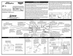
Thank you for your purchase of the Skylink garage door remote
control, Model 69. There are 3 different steps you need to setup in order to use this universal garage door remote control to
operate your existing garage door opener. These 3 steps are:
®
Diagram A
A
USA
Please follow the detailed instructions below in order to setup the Skylink Model 69 to work with your existing opener.
STEP
1
C
D
Chamberlain
®
Lift-Master
®
Sears
®
Wayne Dalton
®
Master Mechanic
®
Genie
®
Overhead
®
Pulsar/Allister/Allstar
TM
®
Linear MegaCode
®
Linear
®
M-O-M
®
Stanley
®
Multi-Code
®
Martec/Teckey
®
Skylink UR-100
USA
CANADA
Set switch
Set switch
to position Frequency to position Frequency
A
A
A
D/A
A
A
A
B
B
C
C
C
D/C
D
A
390
390
390
300/390
390
390
390
318
318
310
310
310
300/310
300
390
C/A
C/A
C/A
C/A
C/A
C/A
A
B
B
D
D
D
D
A
315/390
315/390
315/390
315/390
315/390
315/390
390
318
318
310
310
310
310
390
Chart 1
STEP 3 - LEARN CODE
Brand jumpers setting Proceed to
A
B
+
Proceed
to Step 3.
Note:
Proceed to this step only if the brand of your garage door opener belongs
to either group 1, 2 or 3 on chart 2. Otherwise, proceed to Step 4 - Set
code connector.
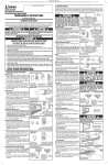
3a. If your existing garage door opener belongs to any brand from group 1,
2 or 3, then you should find a “learn” button from the garage door opener
(the unit with the motor located on the ceiling of your garage, see dia3*
+
+
gram D). Press this learn button for approximately 2 seconds. The
4
+
0
LED light beside the learn button will go on and then press the button
Proceed
5
+
on the Model 69 to activate it. The LED light on the garage door opener
to Step 4,
will flash then go off.
skip Step 3.
6
The Model 69 is now programmed
Garage Door
7
0
+
to your existing garage door opener
Opener (GDO)
8
0
and will operate your garage door.
Programming is now completed
Chart 2
* Note:
and please refer to the “Battery”
For Genie® IntellicodeTM, if the brand jumper for group 3 cannot operate your garage door
section of this manual for battery
‘Learn’ Button
opener properly, please use setting A “-”, B “+”.
maintenance.
Diagram D
2
-
0
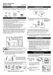
2a. To set the brand
jumpers, open the
case with a coin
(see diagram B).
Code connector Location
B AT TE RY
A = “-”
B = “+”
Diagram B
Brand
Jumper
REMOVE JUMPER = “0”
390 318 310 300
CANADA 390 318 315 310
2 - SET BRAND JUMPER
Chamberlain® , Sears®, Lift-Master®
(without DIP switches but with red, orange or green
learn button)
Chamberlain®, Lift-Master®, Sears®, Wayne Dalton®,
Master Mechanic® (without DIP switches but with
yellow, white, or gray learn button)
Genie® IntellicodeTM * (without DIP switches)
Genie® (with DIP switches), Overhead®
Chamberlain®, Lift-Master®, Sears®, Wayne Dalton®,
Master Mechanic® (with DIP switches)
Stanley®, Multi-Code®, Martec®
Linear®, Moore-O-Matic®
Pulsar®, Allstar®, Allister®, Linear® MegaCodeTM
B
STEP
1b. Determine the brand of your garage door
opener and set the frequency switch to
the corresponding position. (See chart 1)
Brand of your opener
1) Frequency switch – select the correct frequency according
to the brand of your existing garage door opener. Refer to
Step 1.
2) Brand jumpers – place the brand jumpers at the correct
position according to the brand of your existing garage door
opener. Refer to Step 2.
3) Code setting – Set the jumper connectors on the Model 69
so that they match the code setting of your existing garage
door opener.
Refer to Step 3 or Step 4 depending on the brand of your
garage door opener.
Group Brand
1 - SET FREQUENCY SWITCH
1a. Locate frequency
switch on the top of
the transmitter:
(See diagram A)
Diagram C
STEP
2 - SET BRAND JUMPER
2b. The Model 69 contains 2 brand jumpers and 12 code
connectors (see diagram C). The brand jumpers are
located just above the battery with markings “A” and
“B”. There are 2 connectors, one is placed on the “A”
column, the other one is placed on the “B” column.
For each column, there is a connector. If the connector
is placed on the top and middle post of that column,
that column is set on “+”. If the connector is placed
on the middle and bottom posts, that column is set on
“-“. If the connector is removed completely, that column
is set on “0” (see diagram C). In order for the Model
69 to work with your existing garage door opener
(motor), you need to set the brand jumpers based on
the brand of your existing garage door opener. Please
set these 2 brand jumpers “A” and “B” based on the
brand jumpers setting on chart 2. Please identify the
group number on chart 2 in order to determine which
is the next step to proceed.
For garage door openers
belonging to groups 1
to 3, please follow step 3
of the procedures, this will
complete the setup. No
need to proceed to step 4.
For garage door openers
belonging to groups 4
to 8, you can proceed
directly to “Step 4 – Set
Code Connector” after
you have successfully set
the brand jumpers. Please
skip step 3 below.
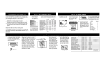
4 - SET CODE CONNECTORS
4c. If the connector is placed on the top and middle posts, that
column is set on “ + ” or “ON” or “CLOSE”. If the connector
is placed on the middle and bottom posts, that column is
set on “ - ” or “OFF” or “OPEN”. If the connector is removed
4a. If the brand of your garage door opener belongs to groups 4 to 8, that means
completely, (not placed on any posts), it is set to “ 0 ” or the
you need to program the correct code setting in order for the Model 69 to
neutral position. (see
‘-’ or ‘OFF’ or ‘OPEN’
work with your existing garage door opener. There are 12 code connectors on
diagram G for examples
12 columns from 1 to 12 (see diagram E). Each column has one connector.
‘+’ or ‘ON’ or CLOSE
‘0’ = BLANK
of how to set a column
(see diagram F)
to the three different
4b. Set the connectors numbered 1 through 12 to match the code setting of your
positions). When reexisting transmitter or receiver. There are 2 places you can find out the code
moving a connector to
setting from a column of small switches of your existing garage door opener.
set a column to the
1) your existing transmitter (the unit you currently use to open your garage).
neutral position, save
2) the receiver of your garage door
the connector in case
opener (the unit with the motor
you change the code
mounted on the ceiling of your
at a later date.
garage).
Diagram G
Diagram F
Diagram E
Note:
Proceed to this step only if the brand of your garage door opener belongs to
either group 4, 5, 6, 7 or 8 on chart 2. Otherwise, proceed to Step 3 - Learn code.
4d. To move the connectors,
slide an opened paper clip
into the side of a connector
and lift. (see diagram H)
When repositioning connectors, place a connector on the two chosen posts,
then push down on the
connector with your finger.
Paper
Clip
Diagram H
Code connector setting to match your opener/motor
Linear
M-O-M
Stanley (310) Canada
Stanley (300)
Multi-Code
Chamberlain
Lift-Master
Sears
Wayne Dalton
Master Mechanic
Genie (9 positions)
Genie (12 positions)
Overhead
Martec/Teckey
Pulsar/Allister/Allstar
Position 1 to 8
Position 1 to 8
Position 1 to 10
Position 1 to 10
Position 1 to 10
Position 1 to 9
Position 1 to 9
Position 1 to 9
Position 1 to 9
Position 1 to 9
Position 1 to 9
Position 1 to 12
Position 1 to 9
Position 1 to 10
Position 1 to 9
+ OR + OR + OR + OR + OR +, 0 (blank), OR +, 0 (blank), OR +, 0 (blank), OR +, 0 (blank), OR +, 0 (blank), OR + OR + OR +, 0 (blank), OR + OR +, 0 (blank), OR -
11,12 set to ‘+’ or ‘-’
11,12 set to ‘+’ or ‘-’
11,12 set to ‘+’ or ‘-’
4 - SET CODE CONNECTORS
If your existing transmitter has fewer than 12
switches, match only the first corresponding connectors. Leave the remaining posts blank (remove
the connectors). Press the button on the transmitter.
If the garage door does not open, reverse all of the
connectors on the model 69. The “ + ” will be
changed to the “ - ” position and the “ - ” position
will be changed to the “ + ” position. (see diagram J)
Original Position
Examples of how to set Model 69
Existing
Transmitter
Model 69
Reversed Position
11,12 set to ‘+’
Diagram J
Diagram I
OPERATION
WARNING
WARRANTY
To operate the model 69
with your GDO properly,
please press the button
on the model 69.
If this transmitter triggers
other garage doors in
your neighborhood,
change all your transmitters and receiver to a
new code setting.
If, within one year from date
of purchase, this product
should become defective
(except battery), due to
faulty workmanship or
materials, it will be repaired
or replaced, without charge.
Proof of purchase is
required.
NOTE:
Transmission range may
be reduced with use on a
metal garage door.
DO NOT let children use
the garage door transmitter without adult
supervision. Children
can injure themselves or
others by the garage
door.
BATTERY
12 volt alkaline battery (size 23A)
included.
FCC
The Universal Garage Door Remote
Control is approved by the FCC
and it complies with Part 15 of the
FCC Rules. Its operation is subject
to the following two conditions :
1. This device may not cause
harmful interference.
2. This device must accept any
interference that may cause
undesired operation.
WARNING:
Changes or modifications to this unit
not expressly approved by the party
responsible of compliance could void
the user’s authority to operate the
equipment.
If your garage door opener is manufactured by (Chamberlain® ,Sears® , Lift-Master®,
Wayne Dalton®, Pulsar® or Master Mechanic®) the switches will have 3 positions,
(“ + , 0, - ”). Set the connectors on the model 69 to match their corresponding positions. If your opener is a Sears®, Chamberlain® or Lift-Master® and the existing
transmitter has three buttons, (see diagram K), the first connector in the model #69
may need to be changed to another position.
If your Chamberlain® ,Sears® , Lift-Master® has 9 DIP switches, match them to the
first 9 connectors on the model 69 and remove the last 3 connectors (connectors
10, 11, 12). If there are only 8 DIP switches on your Chamberlain® ,Sears® , LiftMaster®, match them to the 2-9 position on the model 69 and remove the last 3
connectors (connectors 10, 11, 12). Now you may have to change the positioning
of the #1 connector on the model 69. If the large
button of Diagram K is used to open the garage
door, set the #1 connector to “ - ” position. If the
middle button is used, set the #1 connector to the
“ 0 ” or “blank” position. If the smaller button on the
left is used, set the #1 connector to the “ + ” position.
Diagram K
NOTE
If your Skylink Universal Remote Control does not
activate your Garage Door Opener, the reason may
be that your GDO age or manufacturer is not listed
on the compatibility chart.
The solution is the Skylink UR-100 Universal Receiver.
If you would like to order Skylink’s product or have
difficulty getting your Skylink’s remote control to work,
please :
1. visit our website FAQ at www.skylinkhome.com,
or
2. email us at [email protected]
(reply within 24 hrs)
3. call our toll free at 1-800-304-1187 from Monday to
Friday, 9 am to 5 pm EST.
Skylink will not be held
liable or responsible for
any misuse or application
of this product other than
for its intended use.
CUSTOMER SERVICE
2213 Dunwin Drive
Mississauga, Ontario,
L5L 1X1, CANADA
(905)608-9223
(905)608-8744 FAX
Email:[email protected]
(Reply within 24 hrs)
Customer Service : (800)304-1187
From 9am to 5pm EST (Mon-Fri)
http://www.skylinkhome.com
P/N. 101A193-001 Rev.1
Patent no. D380895, 5680134,
5841390, 6005508
Patents Pending
©2003 SKYLINK GROUP
®
® are registered trademarks of their respective corporations
STEP
Set the connectors numbered 1 through 12 to match the
switches of your existing transmitter or receiver. If your
garage door opener is manufactured by (Stanley ®, Genie® ,
Multi-Code® , Linear® , Moore-O-Matic® ) these switches
may only have two positions, ( “ + , ON, CLOSED” and “ - ,
OFF, OPEN”). (see diagram I) Set the connectors on the
model 69 to “ + ” if your existing switches are either “ +,
ON, CLOSE ” and set to “ - ” if your existing switches are
either “ -, OFF, OPEN”. Do not use the blank position “0”.
GARAGE DOOR/GATE
REMOTE CONTROL
USER'S INSTRUCTIONS
(Model 69)