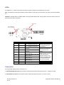
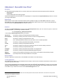
1
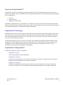
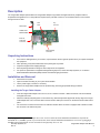
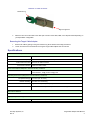
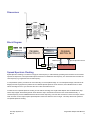
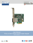
Target Cable Adapter
User Manual
OSS-PCIe-HIB4-x4
2235 Enterprise Street, Suite 110
Escondido, CA 92029
Phone: (760) 745-9883
Fax: (760) 745-9824
www.onestopsystems.com
One Stop Systems, Inc.
Rev. A
Target Cable Adapter User Manual
Overview of SuperSwitch™
SuperSwitch is an extension of the Max Express Expansion System to allow communication between processors over the PCI
Express bus at speeds of 10Gb/s. SuperSwitch offers several significant advantages over other high speed networking technologies
such as 10Gb Ethernet:
•
•
•
Lower cost
Higher performance
Available in more form factors
SuperSwitch configurations allow for communication to a combination of processors as well as external stand-alone PCI Express
devices or expansion systems. SuperSwitch also provides a simple way to network between various computer architectures such as
CPCI, laptops, desktop systems or PICMG passive backplane architectures.
SuperSwitch Technology
SuperSwitch consists of two or more host interface boards (HIBs) and a software driver package called ExpressNet. Each system
uses a HIB, which is connected by cables either to another HIB or through a PCI Express switch to several HIBs. The HIBs use a
PCIe non-transparent bridge to map the memory on each system into the memory space of the others. This allows high speed
direct memory access between the systems.
The ExpressNet software sets up one CPU as the root complex, which initializes the ExpressNet network and handles the fabric
management. It provides standard network services like TCP/IP between the connected systems and also Direct Data Transfer
(DDT) between user level applications. DDT implements a high speed, low latency shared memory that can be used in a
customized communications scheme appropriate to the application.
SuperSwitch Configurations
SuperSwitch is available in three base configurations:
SuperSwitch 1 (2 ports)
Communication between 2 Host Interface Boards
SuperSwitch 2 (3-5 ports)
These ports can all be processors, or they can be any combination of processors, or end points such as a PCIe device,
SHB-ELB, Target Cable Adapter, ECA, CPCI HEB or CPCIe ELB.
SuperSwitch 3 (6-8 ports)
A HIB in the host system communicates through an external 1U 8 port PCI Express switch to be any combination of
processors, or end points such as a PCIe device, SHB-ELB, Target Cable Adapter, ECA, CPCI HEB or CPCIe ELB
One Stop Systems, Inc.
Rev. A
Target Cable Adapter User Manual
2
Description
The Target Cable Adapter (Part # OSS-PCIe-Target Cable Adapter-x4) provides the target-side link for peripheral CPUs in
SuperSwitch Configurations. It is a low profile PCI express (PCIe) card that connects to a host interface board, or PCIe switch
through a PCIe x4 cable.
Slot Cover
PEX
8508
Dip
Switches
Cable Lane
Status LEDs
PCIe x4
Cable Port
Connector
PCIe x4 Edge
Connector
Unpacking Instructions
1.
2.
3.
4.
5.
If the carton is damaged when you receive it, request that the carrier's agent be present when you unpack and inspect
the equipment.
After unpacking, verify that all items listed in the packing list are present.
Inspect the equipment for shipping damage.
Save all packing material for storage or return shipment of the equipment.
For repairs or replacement of equipment damaged during shipment, contact One Stop Systems, Inc. to obtain a
Return Materials Authorization (RMA) number and further shipping instructions.
Installation and Removal
1.
2.
3.
4.
Power down the system.
Open the chassis according to your system documentation.
Let the power supply cool down, if necessary.
Remove the Target Cable Adapter from the protective bag, observing proper ESD safety procedures.
Installing the Target Cable Adapter:
1.
2.
3.
1
Insert the Target Cable Adapter into a PCIe x4, x8 or x16 add-in card slot . Make sure that the card is well seated,
and tighten the screw.
Attach the cable by first pulling back on the retractor ring. With the keyed slot aligned with the key ridge of the Target
Cable Adapter slot cover, insert the cable connector into the cable port connector on the board until the cable locks in
place.
The connectors on either end of the PCIe x4 cable are identical. Each connector is equipped with a retractor to allow
the connector to be locked into place.
1
“Up-plugging” the Target Cable Adapter into a x8 or x16 slot is allowed, but the motherboard manufacture may limit the
bandwidth to x1 (250MB/s) speeds. If you need to do this, check with the motherboard manufacturer to see how up-plugging is
handled on their motherboards. A PCIe x4 board will not physically fit in a x1 slot.
One Stop Systems, Inc.
Rev. A
Target Cable Adapter User Manual
3
Retractor on Cable Connector
Retractor ring
Alignment grooves
4.
Attach the other end of the cable to the cable port connector of the HIB2, HIB5, or PCI Express switch depending on
your SuperSwitch configuration.
Removing the Target Cable Adapter:
1.
2.
Remove the cable by pulling on the green retractor ring which releases the locking mechanism.
Loosen and remove the screw before removing the Target Cable Adapter from the card slot.
Specifications
Electrical/Mechanical Specifications
Form Factor: PCIe x4 add-in card
Dimensions (H x L): 2.713 x 4.395 inches (68.9 x 111.6mm)
Front Panel Connectors: One PCIe x4 cable connector
Front Panel Indicators: Cable Lane Status LEDs
Power Consumption (designed to meet the following conditions
6.5W maximum, 12V@ .4A and 3.3V@ .45A
Operating Environment (designed to meet the following conditions)
Temperature Range: 0° to 50°C (32° to 122°F)
Relative Humidity: 10 to 90% non-condensing
Shock: 30g acceleration peak (11ms pulse)
Vibration: 5-17 Hz 0.5” double amplitude displacement; 7-2000Hz, 1.5g acceleration.
PCI Express Switches
PLX PEX8508
Agency Compliance Designed to meet, but not tested
UL60950, FCC Class B, CE safety and emissions
One Stop Systems, Inc.
Rev. A
Target Cable Adapter User Manual
4
Dimensions
4.395”
2.713 “
Block Diagram
LEDs
100.1 Mhz CFC Clock
X4 Cable
Connector
LANES (3:0)
Spread Spectrum Clock
PEX8508
SWITCH #1
LANES (3:0)
PEX8508
SWITCH #2
LANES (3:0)
Spread Spectrum Clock
12V
1.0V
1.5V
3.3V
X4 PCI Express Card Edge
Spread Spectrum Clocking
Spread Spectrum Clocking is a method of varying the clock frequency to reduce EMI by spreading noise emissions across a broad
spectrum of frequencies. The required PCI Express method is to modulate the clock frequency in a manner that does not allow the
clock frequency to go higher than the nominal frequency.
In a SuperSwitch system, processors are connected using a non-transparent bridge. In a non-transparent bridge, both sides of the
bridge (Host and Target) have the potential to use individual Spread Spectrum Clocks. However, the modulated clocks on either
side of the bridge are not in sync with each other and could cause data to be lost.
To allow the use of Spread Spectrum Clocking on both sides of the bridge, the Target Cable Adapter uses two 8508 switch chips.
These chips support “Dual Clocking Mode” which allows the chip to transmit and receive two PCIe clocks simultaneously. A
constant frequency clock is established between the two switch chips using one of the PCI Clock lines on each of the chips, and the
other clock line on each chip accepts a Spread Spectrum Clock from either the Host or Target. This setup allows both systems to
use Spread Spectrum Clocking.
One Stop Systems, Inc.
Rev. A
Target Cable Adapter User Manual
5
Switches
The Target Cable Adapter contains one x4 dip switch. See Spread Spectrum Clocking section for an explanation of how the Target
Cable Adapter handles Spread Spectrum Clocking when SW1-1 is ON. See Addendum C – Switch and LED technical reference
guide for details on the switch settings.
SW1
Description
ExpressNet
Settings
1
Spread Spectrum Clock
Support
ON
OFF = Single Clock Mode
ON = Dual Clock Mode
2
8508 #2
NT Mode Select
OFF
OFF = Dual Host Mode
ON = Intelligent Adapter Mode
3
EEPROM #1 Present
OFF
OFF = EEPROM not present
ON = EEPROM is present
4
EEPROM #2 Present
ON
OFF = EEPROM not present
ON = EEPROM is present
Card Edge
ON
1 2 3 4
Push switch in the
indicated direction
to achieve the
desired setting.
OFF
SW1
One Stop Systems, Inc.
Rev. A
Target Cable Adapter User Manual
6
LEDs
See Addendum C – Switch and LED technical reference guide for details on the interpretation of the LEDs.
CR1: 1x4 Quad LED on front panel indicates Lane Good Status for each of the four PCIe lanes on the cable. The lanes are labeled
0-3.
CR2-CR11: Individual LEDs on the BACK SIDE of the Target Cable Adapter PCB. The figure below shows the locations, order and
placement of the LEDs on the board.
CR2 – CR9
CR 10 and CR 11
(CR12 not populated )
LED #
CR2
PCB Label
PG1
CR3
PG2
CR4
FE1
CR5
FE2
CR6
0
CR7
1
CR8
2
CR9
3
CR10
CR11
SEQ_GOOD
CE_RST
Function
Internal port good indicator for
lane on 8508 PCIe switch #1
Internal port good indicator for
lane on 8508 PCIe switch #2
Fatal error indicator for PCIe
switch #1
Fatal error indicator for PCIe
switch #2
PCIe lane status on the card
edge for lane 0
PCIe lane status on the card
edge for lane 1
PCIe lane status on the card
edge for lane 2
PCIe lane status on the card
edge for lane 3
Power Good indicator for board
Card Edge PCIe reset
Description
When lit, these two LEDs
indicate a good PCIe lane
connection between the
two switches
When lit these two LEDs
indicate an internal Fatal
Error signal from the
switch
These four LEDs are
labeled together as “HOST
LANE GD” below the
individual numbers, and
indicate a valid signal level
on the appropriate PCIe
lane of the Card Edge.
Connectors
The Target Cable Adapter has two connectors on it:
1. PCIe X4 Card Edge Connector per PCI Express Card Electromechanical Specification Revision 1.1 (March 28, 2005)
2. PCIe X4 Cable connector per PCI Express External Cabling Specification Revision 1.0 (January 4, 2007)
One Stop Systems, Inc.
Rev. A
Target Cable Adapter User Manual
7
Addendum A - ExpressNet Linux Driver2
Description
The ExpressNet software package for Linux consists of three major components and their associated include and make files.
- The kernel driver
- A user library
- A demonstration/performance testing program
These are all supplied as source files written in C and packaged in a compressed tar file expressnettar.bz2, provided on a CD with
your Target Cable Adapter.
Requirements
64-bit version of Linux, with Linux kernel version 2.6.20 or greater running on a 64-bit AMD or Intel CPU. However,
ExpressNet may work in simple configurations with earlier versions and/or 32-bit versions of Linux. Kernel module dependencies
are documented in the html/readme.html file contained on the CD.
Extraction
The files in the expressnettar.bz2 file all untar into the opt/ossi/expressnet directory tree. For most Linux system, to untar it into
the standard location, /, you must log in as root and execute:
cd /; tar xvfj directory_path/expressnettar.bz2
In the resulting /opt/ossi/expressnet directory you will find:
applications
The directory containing the ExpressNet demonstration program.
documentation
The directory containing documents not found in the html or manpages directory.
driver
The directory containing the ExpressNet Linux driver.
filelist
A list of all ExpressNet files installed in the system that is used to uninstall ExpressNet.
html
The directory containing ExpressNet documentation in web format.
include
The directory containing the ExpressNet include files.
init.d
The directory containing the script which enables the system to control the loading of the driver.
lib
The directory containing the ExpressNet library files.
manpages
The directory containing ExpressNet documentation in manpage format.
pexload
The directory containing the ExpressNet EEPROM programming utility.
INSTALL
A shell script that compiles and installs the driver and library and compiles the demonstration program.
UNINSTALL
A perl script that removes all ExpressNet files on the system.
Driver Installation
Follow the explanations and instructions in the README documentation in the HTML directory.
Licensing Agreement
This program is free software; you can redistribute it and/or modify it under the terms of the GNU General Public License version 3,
or (at your option) any later version.
This program is distributed in the hope that it will be useful, but WITHOUT ANY WARRANTY; without even the implied
warranty of MERCHANTABILITY or FITNESS FOR A PARTICULAR PURPOSE. See the GNU General Public License for
more details. A copy of this license can be found in documentation/gpl.txt on the CD.
2
The following information was correct at the time this manual was published. Please read the readme.html on the CD for the most up to date
requirements and installation procedures.
One Stop Systems, Inc.
Rev. A
Target Cable Adapter User Manual
8
Addendum B – SuperSwitch Configurations
SuperSwitch 1
PCI Express-over-cable solutions for point-to-point communications
•
•
•
•
•
SuperSwitch 1 includes one PCIe x4 host adapter attached via a PCIe x4
cable to a CPCI Express x4 cable adapter,
PCIe x4 cable adapter or Express Card and ExpressNet software suite.
Data transfers between two systems occur at 20Gb/s.
ExpressNet software supports 64 bit CPUs as well as multithreaded
environments.
PCIe cables in 1m, 2m, 3m, 5m and 7m lengths.
Part #: OSS-SS1-X-XM
SuperSwitch 2
PCI Express-over-cable networking for 3 to 5 PCs
•
SuperSwitch 2 includes connecting up to five processors using one
PCIe x4 mezzanine cable adapter, up to four PCIe x4 cable adapters,
PCIe cables up to 7 meters and ExpressNet software suite.
Enables data transfers at speeds up to 20Gb/s.
ExpressNet software supports 64 bit CPUs as well as multithreaded
environments.
PCIe cables in 1m, 2m, 3m, 5m and 7m lengths.
•
•
•
Part #: OSS-SS2-X-XM
SuperSwitch 3
PCI Express-over-cable networking for 6 to 8 PCs
•
•
•
•
SuperSwitch 3 includes connecting up to eight CPUs or any
combination of CPUs and I/O devices, using one 8-port 1U switch, one
PCIe x4 host adapter, Express Card or CPCIe host adapter, up to 7
PCIe host cable adapters, up to 8
PCIe cables and ExpressNet software suite.
Enables data transfers at speeds up to 20Gb/s.
ExpressNet software supports 64 bit CPUs as well as multithreaded
environments.
Part #: OSS-SS3-X-XM
One Stop Systems, Inc.
Rev. A
Target Cable Adapter User Manual
9
Addendum C – Switch and LED technical reference guide
Switches
Switch SW1-1 Spread Spectrum Clock: ExpressNet is not dependant upon either Single or Dual Clock Modes; it is PCIe Link negotiation and
data recovery in association with PEX8508 clock recovery that governs subsequent Link operability. SW1-1 should be set ON to enable Dual
Clock Mode and Spread Spectrum Clock support. Single Clock Mode (SW1-1 OFF) is for testing purposes only. For more information, read the
Spread Spectrum Clocking section on page 5.
Switch SW1-2 NT Mode Select: ExpressNet usage requires that PEX8508 #2 utilize Dual-Host Mode (SW2-2 OFF). In a Dual-Host application,
the PEX8508 is used to isolate the two hosts, by routing traffic through the NT Port by way of two x4 links. Intelligent Adapter Mode (SW2-2 ON)
is NOT applicable to ExpressNet operation via PEX8508 #2.
Note that PEX8508 #1 is hardwired for Transparent Mode.
EEPROM Usage: The optional EEPROMs are used to initialize the PEX8508 registers for ExpressNet usage. The current ExpressNet Driver
software uses unique, EEPROM information supplied to PEX8508 Chip #2, but uses all Default register values from PEX8508 Chip #1. This
requires that the EEPROM for Chip #2 be Enabled (ON), and the EEPROM for Chip #1 be Disabled (OFF). Read more under Switch SW1-3 and
Switch SW1-4, below.
Both EEPROM’s can be reprogrammed in the field for special needs by following the supplied ExpressNet documentation or
directions from customer support
Switch SW1-3 & EEPROM #1 Contents: The contents of this EEPROM are blank or the EEPROM is not populated. The default PEX8508
values for PEX8508 Chip #1 are required for ExpressNet usage and, therefore, it is mandatory to set SW1-3 to OFF to disable EEPROM #1.
Switch SW1-4 & EEPROM #2 Contents: This EEPROM supplies the board's unique Serial Number to the ExpressNet Driver, which uses the
number in formulating a MAC address. Additional Manufacturing information is also contained in EEPROM #2. The EEPROM settings also
disable unused BARs, Devices and Links within the PEX8508. Though the ExpressNet Driver is still fully functional when EEPROM #2 loads
Default values instead of EEPROM values, it is recommended to set SW1-4 to ON to enable EEPROM #2 usage.
Default values will also be loaded if the PEX80508 discovers that its EEPROM contents are corrupted (CRC mismatch).
LEDs
LED Usage: CR1 Front Panel Lane Good Status [green]. If the HIB4 board's cable is plugged into an HIB2, for example, it should then have all
four Lane LEDs lit, signifying correct x4 operation (this assumes that the HIB2 is itself powered up!). If only 0 is set, this signifies only x1 Lane
operation. The system will continue to perform normally with x1 Lane Width, but with lower throughput due to the lesser number of PCIe lanes
available. Having 2 or 3 Lane Good LEDs lit is an abnormal condition.
LED Usage: CR2/3 Port Good [green]. Both of these LEDs must be lit for correct operation. They should be lit regardless of whether either end
of the cable is connected, and regardless of the state of any hardware connected to the far end of the cable. If they are not lit, it indicates that a
PCI Express link was not established between the two PEX8508 chips and communications between the two cannot occur.
LED Usage: CR4/5 Fatal Error [red]. These LEDs should never be lit as they indicate a PEX8508 internally detected error. Contact OSSI
Customer Service for further assistance.
LED Usage: CR6,7,8,9 Host Lane Good Status [green]. The HIB4 board should have all four Lane LEDs lit, signifying correct x4 operation.
Having 1 Lane Good LED lit (CR6) is operational, but indicates x1 operation. (See note on up-plugging in installation section) Having 2 or 3 Lane
Good LEDs lit is abnormal. Blinking LEDs signify the Lanes are going up and down, a bad situation. Ensure that Switch SW1-1 is ON, allowing
Spread Spectrum support. Alternately, attempt to disable Spread Spectrum Clocking from within your system’s BIOS to test whether you might
be encountering an out-of-bound Spread Spectrum clock from the system's PCIe bus.
LED Usage: CR10 SEQ_GOOD [green]. This LED is lit by detection of the +3.3V level and should always be lit once power is stable.
LED Usage: CR11 CE_RST [red]. This LED is lit only when the board is in a reset state. BIOS and PCIe bus resets can cause this LED to blink.
This is an informational LED only.
LED Usage: CR12 CBL_RST [red]. This LED is not connected and/or not populated. The capability to monitor the reset signal driven from the
upstream end of the cable is reserved for future use.
One Stop Systems, Inc.
Rev. A
10
Target Cable Adapter User Manual
Limited Warranty
One Stop Systems warrants this product to be free of defects in material and workmanship for an initial period of two years from
date of delivery to the original purchaser from One Stop Systems.
During this period, One Stop Systems will, at its option, repair or replace this product at no additional charge to the purchaser,
except as set forth in this warranty agreement.
One Stop Systems will, at its option, repair or replace this product at no additional charge to the purchaser, if the defect is related to
the One Stop Systems manufactured product, such as a power supply, backplane, other chassis components or CPUs. One Stop
Systems is not liable for any defects in material or workmanship of any peripherals, products or parts, which One Stop Systems
does not design or manufacture. However, One Stop Systems will honor the original manufacturer’s warranty on these products.
One Stop Systems will analyze the defective component and the customer will be charged in the following instances:
•
•
No problem found: $75 (U.S. dollars).
Damage: Parts and labor at $75 per hour with a $100 minimum charge (U.S. dollars). Receipt of damaged goods voids the
One Stop Systems warranty.
Repair parts and replacement products will be furnished on an exchange basis and will be either new or reconditioned. All
replacement parts and products shall become the property of One Stop Systems, if such parts or products are provided under this
warranty agreement. In the event a defect is not related to the One Stop Systems manufactured product, One Stop Systems shall
repair or replace the defective parts at the purchaser’s cost and deliver the defective parts to the purchaser.
This limited warranty shall not apply if the product has been misused, carelessly handled, defaced, modified or altered, or if
unauthorized repairs have been attempted by others. The above warranty is the only warranty authorized by One Stop Systems and
is in lieu of any implied warranties, including implied warranty of merchantability and fitness for a particular purpose. In no event will
One Stop Systems be liable for any such damage as lost business, lost profits, lost savings, downtime or delay, labor, repair or
material cost, injury to person or property or any similar or dissimilar consequential loss or damage incurred by the purchaser, even
if One Stop Systems has been advised of the possibility of such losses or damages.
In order to obtain warranty service, the product must be delivered to the One Stop Systems facility, or to an authorized One Stop
Systems service representative, with all included parts and accessories as originally shipped, along with the proof of purchase and
a Returned Merchandise Authorization (RMA) number.
The RMA number is obtained, in advance, from One Stop Systems Customer Service Department and is valid for 30 days. The
RMA number must be clearly marked on the exterior of the original shipping container or equivalent. Purchaser will be responsible
and liable for any missing or damaged parts. Purchaser agrees to pay for shipping charges one way, and to either insure the
product or assume the liability for loss or damage during transit. Ship to:
One Stop Systems
ATTENTION: RMA REPAIR DEPARTMENT
RMA ####
2235 Enterprise Street, Suite 110
Escondido, CA 92029
www.onestopsystems.com
2235 Enterprise Street, Suite 110 y Escondido, CA 92029 y Tel (760) 745-9883 y Fax (760) 745-9824
One Stop Systems, Inc.
Rev. A
11
Target Cable Adapter User Manual