1
United States Patent [191
[1 1]
[45]
McClung et a1.
[54]
METHOD AND APPARATUS FOR
4,549,281 10/1985 Eckert et a1. ..................... .. 364/900
4,558,175 12/1985 Genest et a1.
SYSTEM
4,621,334 11/1986
Garcia ....... ..
4,622,651
Eckert
R.
Baldwin, N‘YG
P tar H Roberts Brook] n N Y
e
_
Asslgnee:
'
’
y '
'
‘
Harcom Security Systems Corp.,
_
_
. . . . . .. . . . . . .
5/1987 POfChEl" CI 8.1. .
8/1987 Thomas ......... ..
4,713,753
l2/l987
4,757,533
7/1988
Boebert et al. .
380/21
340/8253 x
. . . . . . . ..
364/900
....... 1. 364/900
340/82S.3l X
....... ..
364/200
Allen et a1. ..................... .. 380/23 X
_
_
Pnmanz Exammer-—David L. Clark
Attorney, Agent, or Firm-Schechter, Brucker & Pavane
[21] Appl. No.: 328,735
Filed:
11/1986
4,667,307
4,685,055
New York’ N_Y_
[22]
4,951,249
Aug. 21, 1990
CONTROLLED ACCESS To A COMPUTER
Inventors:
[73]
Patent Number:
Date of Patent:
[57]
Mar. 23, 1989
ABSTRACT
.
A computer security system protects the computer
.
.
software from unauthorized access and the computer
‘ Related “'8' Applicant)“ Data
[63]
[51]
[52]
hardware from unauthorized intrusion. At the start up
Continuation of Scf- NO- 912.600, Oct 24. 1986. aban-
of the computer system, the computer’s keyboard and
donedInt. cl.5 ....................... .. G06F 12/14; H04L 9/00
us. (:1. .................................... .. 364/900; 330/23;
330/25; 34g/325_ 34
diskette drive are disabled. The user is required to iden
tify himself through the use of 2* Hon-keyboard device
Such as a magnetic card reader- AS a means of further
validation, the user enters a PIN via the keyboard
[53] Field of Search
364/200 MS File’ 900 MS File;
340/3253, 3253], 32532;; 380/3, 4, 23’ 25, 52
.
which has now been restored to function. A valid user
will be allowed access to those programs for which he
_
[56]
has been preauthorized. Attempts to gain access to the
References C'ted
operating system or to programs for which the user is
U.S. PATENT DOCUMENTS
not authorized will be ?ltered by the security system to
.
prevent unauthorized access to certain programs or to
23%;“; """"""""
3,806,882
4/1974
Clarke
. . . . .. . . ..
0)?
. . . . r . ..
preclude efforts to thwart the security system. An alarm
circuit provides security to the computer hardware.
364/200
4,494,114 1/1985 Kaish
364/900 X
4,532,508 7/1985 Ruell ......................... .. IMO/825.34
27 Claims, 8 Drawing Sheets
200
POWER-ON
,.
CONTROL/ALT/DEL
~20l293 200
2x0
2'5
215 2'? 2'3
as" t a“
@152‘.
‘
202
SECURITY
svsreu
l
305.,
30"[211
cmuns
wrs 913816
"o"
L~2i3
IMULATE
1m 0355mm
.
_
r219
:wcnvE sTATus com:
206
a
é‘srggn'v
F %‘
/é>
5
22° mam ms 9,
PROGRAM
32A] cam-rm: mrs _
I,
2 ,
o
To
$868?»
as 3
(PL?)
INITIATE sw Wm
2st
224
T0 ran FL? 51
_‘
>--—'2so\
J
szcunrrv
svs're
ease
‘
51%".
PROGRAM
(sum
2
,_
23r~~v
=
AFTER 3 Times
nMPu'r
we ArrEuPriL" NOT
233
I? up
227 vlud”
vauuza
245/“
239
m
mt
mu
242.\_ STORE Pnncnm no:
a 2ND Paoeam
Aunmlzmon m PLP
mm
AREA
1
U SEE
APP‘LJBAT lm
PROGRA I
1
US. Patent
Aug. 21, 1990
4,951,249
Sheet 2 0f 8
200
/
POWER ‘ON
CONTROL/ALT/DEL
209
2OIZCP3 294 (
21o
I
OPERATING
2‘? 2)6 2IT ZIP
'
I
'
I
'
I
SW'BQTRT ) I9%}? 55591455,, Lgggg LE?EgUTE
SYSTEM
'
-
RoUTINEs
202
sEcURITY
SYSTEM
ROM
DISKETTE
Lg}?
205“ 12p? “2"
cAPTURE
INTs 9,138Il6
I
HARD
ExEI: BAT
DISK
'
»2I3
J
SIMULATE
INT I3-_RETURN
“
INAcTIvE sTATUs CODE
SECURITY
sYsTEM
220
fRgggM
f2l9
RESTORE lNTS‘9J38Il6
F‘OCM.3
ZZZNIGAPTURE INTs 2I a 24]
PROGRAM
To
y
(PLP)
> ‘
RG3
SIMULATE INT 2I-4BOO TO
INITIATE sMP WITH RETURN
1237
224*‘ TO NExT PLP STATEMENT
B
_*
229 E"-”% ,9
SECURWY
sYsTEM
235/“
SIGNQN-
ANY éENTORMAI.
I
2/
LIIEONGJRAM
REQUIRE INsERT OF PREVIOUSLY
AUTHORIZED IOENTIFIcATION
23'
CARD AND PIN
IF INPUT
v___AFTER 3 TRIEs
IsMPI
LOG ATTEMPT
233
NOT
VALID 229
227
IF INPUT 245 /*
VALID
239 $0
ALLOW OPERATOR
To SPECIFY PROGRAM
$24M
'
242,» sTORE PROGRAM NAME
& 2ND PROGRAM
AUTHORIZATION IN PLP
DATA AREA
I
l_r—’—__—__
243
USER
APPLICATION
PROGRAM
FIG‘. 2
US. Patent
Aug. 21, 1990
Sheet 3 of 8
266
4,951,249
269
EXlT———>—
EXECUTE
‘
NORMAL‘
SERVICE
ROUTINE
RETURN+
267
IF
AUTHORIZED
a?
M265
1
255
T0 FIG.2
.
IF
1
ABNOR'MAL
“5855"”
+NOI§MALTCHECK
ATTEMPT , 260
I
257
TO INITIATE 008
236
244
,
I
‘
FUNCTION OR A
F
,- -- SIMULATE INT 2|—4BOO
,
T0 INITIATE PROGRAM
;
SETUP BY sMP WITH
"
RETURN TE NEXT PLP
STATEM NT
FROM
FlG.c
r"
27'
2ND
{
‘
,
~
J
-'\
245
PROGRAM
259,5.
262
IF NOT AUTHORIZED J
DISPLAY ERROR
MESSAGE
f26|
247
I
f'\
V
V
a
4
‘
V
“T277
1263
253
273
r
11
r
CONTINUE START
“swam CONTINUE
*
'
A
250K ExEcunON
PROGRAM YEX|T-——>--4EX|T¢7_
275
257
F763
i
sEcONOARY
PROGRAM
EXECUTION
;
278
A
US. Patent
Aug. 21, 1990
445"
ALE
AEN
N9
|
Sheet 4 of8
4 3 42, 43
735
£507
423
n
H
ZZQRUNESVALID
449
/
/
439 ' :lj—‘/4s|
H'GH MEMORY‘
JUMPER | PAIR
Aa
TO SET BOARD
4
Al? -A|4
F9
4,25
65
454
—~
4 um: T0
ISLINE DECODER ii
RESPONSE ADOR.
457
,
‘ 455
I
43:
-
A" N4
41,5
_
cs
OCTAL 3 STATE
BUFFER
‘
INTERNAL
All-A0 ADDR.BUS
A310
4,951,249
44/7 HZIOCTAL
433 ۤ 3
STATE BUFFER \
FIG. 4
469
US. Patent
Aug. 21, 1990
Sheet 5 of8
4,951,249
'?3
{
502
527
-
/
-
A95
5|?
Am
Rig)‘
I9
/50|
A"
505
D
)g
BUS
22%
"ROM" 6
so?
5s?
35
525 529
/
09-07
[aw-FER 5695
'565 W'DT DIRECTION
50
2K
RAM
AD-Auz
573
509
L
577
5-,5
w -<
.
579
F
5°? A0
/
53|
I
ll
A" an
537 543
LNTIROE
Al -
L“ A
w- 545
+5V
A'O'M
AD
FROM HG
513
BINPUT '0
54o
NAND
W
551
_—
CARD READER CLOCK _l-555 O'C/TEL
cARD READER DATA __€~:l55_"l. 3s
CARDIN
STATUS
FROM FIG->ALARM STATUS
FIG“. 5
m.-
4161;,
BUFFER
553
MEMR
5n
533
‘(g
RAM" ’535
/—
INTERNAL
DATA
/
565
521 523
"s?péclji
COMPUTER
5 58‘
MEMW
US. Patent
Aug. 21, 1990
Sheet 7 of8
4,951,249
I DISPLAY "INsERT cARD" PROMPTIPATOI
' READ DATA ATMBSIVF-JFI AND CHECK BIT ‘3 EDR LOGICI
IBIT3=I
MEANS CARD HAS BEEN INSERTED)
“N0” I<—L—>EQUAI_ In
I703
IDISPLAY " REMOVE cARD" PROMPTI/ 705
{I
70?“ READ DATA AT BB=FFI AND CHECK BIT 3 FOR LOGIC D J
(BIT 3 = ID MEANS CARD IS BEING REMOVED)
I
YOQV-LSTART " TIMEOUT" COUNTER?F
READ DATA ' AT BS=FFI AND CHECK BIT I FOR LOGICI
(BITI = I MEANS CLOCK IS HIGH)
‘-->EQUAL I
L'fII
lsToRE BIT 2
(DATA BITH» TIs
i
[REsTART TIMEOUT
couNTEI?/ 7|?
(I
READ DATA AT BB=FFI AND CHECK BIT I
FOR LOGIC 0 (CLOCK LOW)
\
NOT=0‘—i—-EQUAL III
CHECK TIMEOUT
I
7'9
72I
NOT TIMEOUT TIIIIEouT1
1255
LSEARCH STORED DATA BIT STRING FOR START SENTINEL (OIOIIOI I
NOT FDLIND'_I__+I=0LIND~i
coNvERT NExT 5 BITS INTO AscII
72f)
CHAR AND sToREI
i
LCHECK FOR END OF BIT STRINGI/~ 727
NOT END OF STRING‘_L_>END OF STRING
[DISPLAY ERROR MESSAGE
729
EXIT
PROGRAM
FIG. 7
1
4,951,249
2
operating system and thus the ability to bypass the secu
METHOD AND APPARATUS FOR CONTROLLED
ACCESS TO A COMPUTER SYSTEM
This is a continuation of US. Application Ser. No.
922,600 ?led Oct. 24, 1986, now abandoned.
rity program.
It is also possible for a user to insert a diskette into the
disk drive found in most computer systems which will
enable him to gain access to the operating system and
bypass the security functions.
Physical security of the computer system is often
BACKGROUND OF THE INVENTION
provided by wire cable padlocked to the computer and
the desk it sits on. However, this presents little deterrent
This invention relates to a computer security system
which protects the computer software from unautho 0 to a professional thief who can easily cut the cables or
pick the locks. In addition, if a master key is used for all
rized access and protects the computer hardware from
of the locks to make it easy for authorized personnel to
unauthorized intrusion or unauthorized removal. In a
move or repair the equipment, lax handling of this mas
particular, it pertains to a security system for the “per
ter key can render the use of padlocks and cables worth
sonal” computers now in wide use.
less. The computer system itself does not have any
Since their introduction only a few years ago, the
means to alert security personnel that a theft is in
number of personal computers in use in corporations
progress, thus allowing the thief to procede without
and ?nancial institutions has risen dramatically. Many
interruption. Furthermore, the cables and locks make it
?rms have thousands of these computers throughout
their organization. In contrast with the high security
traditionally afforded computer equipment and data in
the past, personal computers are not generally located
in high security areas or operated by a relatively small
number of highly trained and highly trusted personnel.
cumbersome for authorized users to move or repair the
20 equipment or make changes in the installed hardware
options.
SUMMARY OF THE INVENTION
It is the general object of the present invention to
Personal computers are often left on desks where any
25 provide a computer security system that protects both
one a operating system boot diskette can access any of
the computer hardware and the computer software.
the data stored within the computer with the potential
Another object of the invention is to restrict autho
for theft of proprietary information and/or the tamper
rized users to a subset of data ?les and/or programs and
ing with it. In addition, the location of such computers
computer system functions for which they have been
in unsecured areas and its relatively small physical size
preauthorized.
leads to theft of the equipment itself. This theft may
either be of the entire computer or of valuable parts
which are easily concealed so that they may taken past
the security guard.
Present security measures have been little more than
super?cial. Passwords and user identi?cation numbers
that are entered via the keyboard are vulnerable to
“hackers" and employee laxity in maintaining password
secrecy. Because the input is via the keyboard, any
person can attempt to guess a user’s password by trying
different character sequences at random. In addition,
users in groups sharing machines often ?nd it conve
nient to tell others their password in order to facilitate
A further object of the present invention is to allow
certain authorized users complete access to all data and
all capabilities of the system and to allow them to deter
mine the access for other users of the system.
Yet another object of the invention is to make physi
cal removal of the computer hardware dif?cult.
A still further object of the present invention com
prises a method for securing a computer system having
a keyboard and a non-keyboard data entry device. Con~
trol of the computer system is transferred to a security
program. The operability of the keyboard is disabled.
All requests which would place the operation of the
computer outside of the security program are ?ltered.
the second individual’s access to some function which
All operators are required to identify themselves via a
was intended by management to be available only to the 45 non keyboard device. The operators identi?cation is
?rst individual.
validated and operability of the keyboard is restored.
The access control programs in general use to not
restrict authorized users from gaining access to the
Valid users are allowed access only to programs for
which they have been preauthorized.
operating system from which they can thwart the in
Yet another object of the invention comprises a secu
tended security controls. The signon and menu pro 50 rity device where a computer system having a keyboard
grams which require the entry of the password before
and a non-keyboard data entry device. Means transfers
proceeding to load the user’s program selection, must
control of the computer system to a security program.
be initiated by the user or by the automatic computer
Means disables operability of the keyboard. Means ?l
start-up procedure. In the former case, the user has
ters all requests which would place the operation of the
access to all of the operating system functions prior to
computer outside of the control of the computer pro
initiating the program requiring the input of the pass
gram. Means identi?es all operators via a non-keyboard
word In the latter case, the signon-menu program can
device. Means validates the operators identi?cation and
be exited to gain access to the operating system by
means restores the operability of the keyboard. Means
causing an abnormal program exit such as depressing
allows a valid user access only to programs for which
the control/break keys on many computer systems. 60 the user has been preauthorized.
Once access to the operating system is obtained, the
A still further object comprises an alarm for a com
user can run his programs without the security program
in place or possibly change the security program.
Many of the user programs which authorized users of
puter system enclosed in a housing. Tilt detection means
detects a tilting of the computer system. Tamper means
detect the loosening or removal of a screw on the hous
the system may legitimately execute are designed with 65 ing which would allow access to the inside of the hous
out regard to the control over access to the operating
ing. Alarm means is coupled to the tilt detection means
and the tamper detection means for sounding an alarm if
system and provide exits to the operating system them
selves. This, too can provide the user access to the
the computer is tilted or a screw is loosened. Means
3
4,951,249
responsive to a reset instruction from a user authorized
to reset the alarm is provided, the reset instruction being
generated by the security program resident in the com
puter system.
BRIEF DESCRIPTION OF THE DRAWINGS
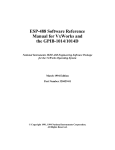
FIG. 1 is an overall block diagram of the computer
security system;
FIGS. 2 and 3 are a flow diagram of the event sequen
ces of the computer security program;
FIG. 4 is a schematic diagram of the board address
decoder and buffer circuits shown in FIG. 1;
FIG. 5 is a schematic diagram of the chip select de
coder and data buffering circuits shown in FIG. 1;
FIG. 6, comprising FIGS. 6A and 6B, is a block 5
diagram of the magnetic card reader interface circuits.
FIG. 7 is a flow diagram of the magnetic card reader
program;
FIG. 8 is a schematic diagram of the alarm circuit.
DETAILED DESCRIPTION
4
produces @ signals on lines 113. One CS signal which
is coupled to the ROM, another is coupled to the RAM
a third coupled to the alarm circuits. Data bus 121 con
nects the output of interface circuit 123. the output of
ROM 115, the output of alarm circuit 119 and the input
/output of data buffer 125 to the input/output of RAM
117. The signals on bus 121 are buffered by data buffer
125 and appear on computer data bus 127 or the signals
on computer bus 127 may be buffered by buffer 125 and
appear on bus 121.
As is well known to those skilled in the art, computer
systems operate under the control of an operating sys
tem. The most common operating system for "per
sonal” computers is the disk operating system (DOS). In
order to avoid the problems of the prior art, it is neces
sary for the security system to act as an intermediary
between the user's application program and the com
puter operating system. FIGS. 2 and 3 contain a ?ow
diagram of the operation of the computer security sys
tem. These ?gures are divided into ?ve levels. Level 1,
shows the functions performed by the operating system
such as DOS. For clarity, details of functions performed
The present invention is illustrated herein for IBM
for programs at other levels are omitted, except where
PC, XT or AT (trademarks of IBM Corporation) com
they are critical for the understanding of the operating
puters or computers which are compatible with these
computers. The present invention is described in con 25 fundamentals of the present invention. Level 2 shows
the functions performed by the security system during
nection with these computers because of their extreme
the initial start up procedure by instructions stored in a
popularity and this should not be taken as an implication
ROM on the security system circuit board. Level 3
that the security system can not be applied to other
shows the security system program loader program
computer systems. The detailed operation of the inter
nal parts of these computer systems is described in the
(PLP) which loads a signon-menu program (SMP) and
all user applications which detects all unauthorized
IBM PC Technical Manual and in the IBM PC Macro
attempts of a user to return to the operating system
Assembler Language Manual and the Intel IAPX 86, 88
level. Level 4 shows the SMP which authenticates users
User's Manual which are well known to those skilled in
and presents them with a list of program options and
the art and which are incorporated herein by reference.
operating system functions which they have been au~
Referring to FIG. 1, an overall block diagram of the
thorized to execute and passes authorized requests back
computer security system in accordance with the pres
to the PLP in order to initiate execution. Level 5 shows
ent invention is generally shown as 100. The system
the execution of user programs and the treatment of
comprises a printed circuit board 102 which ?ts into one
exits from those programs.
of the expansion slots in the computer system and a
FIG. 2 shows the start of the flow diagram at the
magnetic card reader 129 which is coupled to the 40
turning on of the computer or the performance of a
printed circuit board via bus 130. The printed circuit
"soft start” by the simultaneously holding down of the
board comprises four blocks of circuitry. Block 123 is
control, alternate and delete keys on many computer
the interface circuit between the magnetic card reader
systems, as is well known to those skilled in the art. The
and the security system which is described in detail in
connection with FIG. 6. Block 131 contains a circuit 45 chart enters the operating system Level I via path 201
necessary for generating the “board select" (BS) signal
and for buffering the lower address lines All-A0 which
is described in detail in connection with FIG. 4. Block
133 contains the circuits necessary for the chip level
to a start initiation routine block 202. The computer
system is hard wired to transfer program execution to
the BOOTSTRAP code contained in the computer
system boot ROM. The speci?c routines utilized in this
address decoding circuits and the, interface with the 50 process are described in the above referenced technical
reference manual under the heading of BIOS, which
computer data bus and is described in greater detail in
connection with FIG. 5. Block 119 is an alarm circuit
stands for Basic Input and Output System. The initial
ization routines check the working part of the computer
which is described in greater detail in connection with
to be sure that it is completely functional before turning
FIG. 8.
In FIG. 1, the computer address bus 101 is coupled to 55 control over to the operator. During this process, the
control sequence passes via path 203 to block 204 in
address buffers 105 and board address decoder 103.
Buffer 105 buffers the lower order address bits so that
which the operating system scans for a user ROM. Such
ROMs may be installed in the computer system in an
the security system circuit board only presents one TTL
area having a hexadecimal address range of from C8000
load to the computer bus drivers. The board address
decoder 103 decodes address bits A19-A12 to generate 60 through F4000. If a ROM is installed in this address
range and contains the characters AA55 in the ?rst two
a board select signal and a @ signal on bus 107. A board
bytes of the ROM, the operating system will transfer
select signal is coupled via bus 107 to chip address de
control of the computer system to the program con
coder 111 and the CS signal is coupled via bus 107 to the
address buffer 105. The output of address buffer 105 on
tained in the user ROM.
In the present invention, the user ROM is installed on
bus 109 is buffered bits All-A0 which are coupled via 65
the security system circuit board which is plugged into
bus 109 to the chip address decoder 111, to a read only
one of the expansion slots in the computer system. Con
memory (ROM) 115, a random access memory (RAM)
trol of the computer system proceeds via path 205 to
117 and to alarm circuit 119. Chip address decoder 111
5
4,951,249
6
block 206 which contains instructions which will pre
vent operator input via the keyboard until the security
system is in place between the user and the operating
system and which will prevent booting the system from
a diskette. The instructions in the ROM saves the ad
dresses of the operating system keyboard and diskette
service routines in the RAM which is on the security
system circuit board. The above-referenced technical
manual and the IBM PC Macro Assembler Language
Manual contain a detailed description of the way in
which service request routines are handled by an opera
tion system. Basically, the addresses of all service rou
tines are stored in a table in the RAM of the computer.
This table is shown in Table l. The ?rst column of
Table 1 shows the interrupt number in hexadecimal
notation of the interrupt routine. The second column
indicates the address in the computer RAM of the rou
tine which performs the function which is listed in the
third column. The interrupt routines of interest for the
present invention are the diskette/disk routine at hexa
decimal 13 and the keyboard service requests at hexa
decimal 9 and 16. The program stored in the ROM
changes the addresses shown in column 2 of Table l for
that routine. In this manner, the computer security sys
tem can “capture” these service requests and provide
special treatment for them. The program in the ROM
replaces the address of these 3 routines with addresses
of routines contained in the ROM itself which simulate
execution of these routines but do not actually perform
them. Once this has been accomplished, the operation
of the computer system procedes via path 207 back to
block 204, returning control to the operating system.
Control passes via line 209 to block 210 which contin
ues with the initiation routines for the operating system.
One of these routines checks the operational status of
the diskette drive and attempts to read additional boot
code from any diskette in the drive. However, the ad
dresss stored in the interrupt table (Table 1) “captures”
TABLE l-continued
INT #
SOFTWARE INTERRUPT LISTING
ADDRESS IN RAM FUNCTION PERFORMED
l5
54-57
16
58-53
Keyboard
SC-SF
60-63
64-67
68-68
6C-6F
70-73
74-77
78-7B
Printer
Resident BASIC
Bootstrap
Time of Day
Keyboard Break
Timer Tick
Video Initialization
Diskette Parameters
l7
18
l9
[A
0 II!
[C
ID
lE
Cassette
IF
7C-7F
Video Graphics Chars.
20
21
22
23
24
25
26
27
28-3F
40-5F
60-67
68-7F
SO-FO
Fl-FF
80-83
84-87
38-85
BC-SF
90-93
94-97
98-9B
9C-9F
AO-FF
[0D- l7F
l80-l9F
lAO-IFF
200-3C3
3C4-3FF
DOS PGM Tenn.
DOS PM Call
DOS Term. Address
Ctl/break Address
DOS Fatal Error
Abs Disk Read
Abs Disk Write
DOS Terminate
Reserved
Reserved
User INTs
Not Used
Basic
Not Used
The hard disk is operative and the system will look for
a ?le known to the operating system as the AUTOEX
EC.BAT ?le which contains a user de?ned sequence of
programs and procedures to be executed before giving
control over to the operator of the computer system.
The operating system executes the AUTOEXECBAT
?le in block 218. The PLP program must be the last
program named in the AUTOEXECBAT tile.
The operation of the computer system passes via line
219 to block 220. In block 220, when the PLP begins
execution, it restores the normal diskette and keyboard
interrupt addresses thus allowing normal operation of
these two devices. Control then passes via line 221 to
the interrupt routine 13 for the diskette drive and trans
fers it to a routine in the security system ROM via line 40 block 222. In block 222, the PLP saves and replaces the
addresses for the critical error routines (interrupt 24)
211. The program in the ROM at that address will indi
and the DOS function call routine (interrupt 21) and
cate to the operating system that the diskette is not
substitutes addresses routing the calls to routines in the
operative and will then return control via line 213 to the
PLP itself. Thus, these two routines from Table l have
operating system at block 210. Control passes via line
been “captured" and other routines are substituted
215 to block 216 in which the operating system contin
therefore.
ues the initialization process utilizing the boot code
Control passes via line 223 to block 224 in which the
stored on the hard disk of the system.
PLP intiates execution of the SMP by returning control
TABLE 1
to the operating system with pointers equal to the PLP
INT #
0
SOFTWARE INTERRUPT LISTING
ADDRESS IN RAM FUNCTION PERFORMED
0-3
Divide by zero
1
4-7
Single step
2
8-5
Nonmaskable
3
OF
Breakpoint
5
6
7
l4-l7
l8-IB
lD-lF
Print Screen
Reserved
Reserved
8
9
20-23
24-27
Time of Day
Keyboard
A
B
C
D
E
F
10
11
28-28
2C-2F
30-33
34-37
38-38
3C-3F
40-43
44-47
12
13
14
4848
4C-4F
50-53
Reserved
Communications
Communications
Disk
Diskette
Printer
Video
Equipment Check
Memory
Diskette/ Disk
Communications
50 data area to be used by the SMP to transfer the name of
the programs to be loaded by the PLP as the result of
user input to the SMP. As described in the description
of interrupt 4B in the above referenced technical man
ual, the pointers for this function are loaded into regis
55 ters ES:BX. The execution of the SMP via the interrupt
21 4B instruction to the operating system will cause the
operating system to return control to the subsequent
statements in the PLP when the SMP program tenni
nates. This is indicated by the dotted line 226 in FIG. 2
which goes to point B in FIG. 3.
The SMP saves the address of the PLP data area
received in its program pre?x segment. This is the result
of the interrupt 21 48 call by the PLP as described in
the above referenced technical manual in the descrip
65 tion of the DOS control blocks and work areas. Control
passes via line 225 to block 230 in which the SMP dis
plays a prompt to the user to insert and withdraw his
magnetically encoded identi?cation card. The SMP
7
4,951,249
8
then checks the data read from the card. The card
reader interface hardware and the software routine
necessary to read the data from the card are explained in
fuller detail below in connection with FIGS. 6 and 7.
The information on the card is checked against the
entries in the security system ?le of authorized users. If
the card is not an authorized card, that is the security
system does not have this card stored in its ?le of autho
rized users, control passes via line 229 and then via line
231 back to block 230. Setting up the ?le of authorized 0
vector set by the user program. If the exit is the result of
a fatal error or the user depressing the control/break
keys, control passes via line 255 to point A in FIG. 2 at
which the PLP reinitiates the SMP. If the exit is a nor
mal request, control passes via line 257 to block 260
where a check is made to see if there is an attempt to
initiate a DOS function or a second program. The PLP
users is handled in the same manner as any other appli
266. In block 266, the operating system will perform the
cation program.
If the card does match one of the previously autho
rized cards in the security system ?le, the SMP then
requests the user to input his personal identi?cation 5
number (PIN) via the keyboard. The purpose of the
will check the authority indicator by the SMP at block
242 (FIG. 2). If the user is authorized, the PLP will pass
control to the operating system via line 265 to block
requested function and return control back to the user
application program via line 271 or line 273 depending
on the type of service requested. A return passes control
via line 267 to line 271 and hence to line 263 through the
continue input of the secondary program execution
block 278. An exit via line 269 passes control via line
273 to the start input of the secondary program execu
tion at block 278. The secondary programs execute in
PIN is to guarantee that the user of the card is its owner.
Magnetically encoded identi?cation cards can be lost or
otherwise used by persons that are not their owner. The
secret PIN which is known only to the owner and to 20 the same manner as the initial program requested by the
user. Exits from the secondary program pass via line
those authorized to enter such information into the
275 to line 253 back to block 254 and are handled identi
computer’s ?le, greatly reduces a chance of unautho
rized entry or entry into portions of the computer for
which the user is not authorized. If the PIN entered by
the user does not match the one stored with the card
identi?cation number in the ?le of authorized users,
control will pass via line 229 and line 231 back to block
230. If, after two more tries, the user does not enter the
correct PIN, control will pass via 229 and line 233 to
passes via line 235 back to block 224 which restarts the
SMP. If the PIN is correct, control will pass via line 227
and line 239 to block 240. In block 240, the SMP will
cally to exits from the primary program.
Referring now to FIG. 4, the board address decoder
and buffer circuits 131 shown as FIG. 1 are shown in
greater detail. The purpose of the circuit shown in FIG.
4 is to detect that the computer is addressing the com
puter security system circuit and to buffer the address
lines from the address lines of the computer bus so that
they can be utilized in other circuits on the circuit board
without loading the computer bus. The address latch
enable (ALE) signal from the computer address bus is
display a list of programs and functions preauthorized
utilized to latch addresses onto the bus at the falling
by the manager of the security system for this particular
edge of this signal. The address enable (AEN) signal is
user and allow the user to select one of these functions
to be executed by the system. If the user selects one of
these programs of functions, control passes via line 241
to block 242 in which the name of the program is stored
low when the address lines have been driven from pro
gram instructions and high when direct memory access
(DMA) transfers are active. Consequently, when the
ALE and AEN lines are in the low state the address
lines are valid and are being driven by program instruc
by the SMP in the data area of the PLP using the desti
nation address received by the SMP when it was initi 40 tions. The ALE signal is provided to inverter 419 via
line 401 and the AEN signal is provided to inverter 421
ated. At this time, the SMP will also store in this area a
via line 403. The outputs of these inverters on lines 475
code indicating to the PLP whether or not the user has
and 437, respectfully, are input to a two input AND
been authorized to initiate DOS tasks and/or second
gate 445. The result of ANDing these two signals on
level programs.
In normal exit from the SMP will cause control to 45 line 447 is a signal which when high indicates that the
address lines are valid. This signal is applied to one
pass along lines 243 and 245 to point B in FIG. 3. This
input of two input NAND gate 449.
causes the operating system to return control to the
The security system circuit board is designed to re
instruction in the PLP which immediately follows the
spond only to addresses in the range of hexadecimal
one which initiated executed of the SMP. Any abnor
C8000 through F4000 which is the user ROM area of
mal exit from the SMP will be directed to PLP routine
the computer address space. Table 2 indicates the bit
for interrupt 24 at block 236 which will cause control to
patterns for the circuit board general address. As indi
pass via lines 237 and 235 to block 234 and cause the
cated in the Table, lines A19 and A18 must always be
SMP to be reinitiated.
high for the user ROM area to be addressed. Line A19
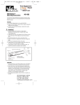
Referring now to FIG. 3, the flow diagram 200 for
is applied to input of AND gate 423 via line 405 and line
the security system program is continued. Line 226
A18 is applied to the other input of AND gate 423 via
enters FIG. 3 at point B and continues to block 244. At
line 407. A high output on line 439, labeled "high mem
block 244, the PLP initiates the execution of the pro
ory” indicates that both of the input lines A19 and A18
gram requested by the user by jumping to the interrupt
are high and that the user ROM is to be addressed. The
21 routine in the BIOS with the AX register set to hexa
decimal 4B00 and with the pointers to the program 60 signal on line 447 and the signal on line 439 are applied
to the inputs of two input NAND gate 449. If both
name in a stated area set up by the SMP. Control passes
signals are high, a low signal appears on line 451 which
via line 247 to the start input 249 to block 250 in which
serves as the chip select (?) signal which is active low.
the program is executed. The user program will execute
This signal serves to enable a four line to sixteen line
normally as if the security system were not present. Any
exit from the user program will pass control via exit line 65 decoder 425, such as a Texas Instruments 74154, which
generates sixteen outputs each which is low for one and
251 and hence via line 253 to block 254. In block 254,
only one of the sixteen different bit patterns applied to
the statement in the PLP that immediately follows the
its four inputs. These inputs are address lines A17
statement initiating the user program analyzes the exit
4,951,249
9
through A14. Table 2 indicates the bit values for the
possible combinations of address lines A14 through A17
on bus 409 which is decoded by decoder 425. One of the
sixteen outputs of the decoder are chosen to limit the
board's response to that particular address simply by
placing a jumper 454 between that output 453 and the
input 455 to inverter 457. Inverter 457 inverts the active
low signal at the output of decoder 425 selected by the
placement of jumper 455 to generate an active high
signal on line 459.
10
dress range of the security system circuit board The
board address range spans a total of 4K bytes. The
lower 2K bytes is devoted to the ROM integrated cir
cuit 527. All but the last 16 bytes of the top 2K bytes is
devoted to the RAM integrated circuit 529. The last 16
bytes of the top 2K bytes is used to address the card
reader data and to control the alarm arm and disarm
circuits. The bit patterns which divide the address range
and which de?ne the requirements for the circuits de
10 veloping the chip select signals are indicated in Table 3.
TABLE 2
A19
C8
CA
D0
D4
D8
DA
E0
E4
E8
EA
F0
F4
GENERAL BOARD ADDRESS OPTIONS
A18
A17
A16
A15
A14
A13
A12
1
l
Not Used
1
l
1
l
1
l
Not Used
1
l
1
l
1
l
Not Used
1
l
1
l
JUMPER
0
0
l
O
O
0
1
0
0
U
1
l
l
O
0
I
0
1
O
0
0
O
O
O
0
2
3
4
l
l
l
0
0
0
O
0
l
0
I
0
O
0
0
0
0
O
5
6
7
l
l
l
l
0
0
0
l
0
0
0
0
8
9
As also shown in Table 2, these addresses require that
The active low board select signal generated on line
lines A12 and A13 be simultaneously low. Line A13 is
467 on FIG. 4 is applied to line 501 in FIG. 5. This
applied to the input 411 to inverter 427, the output of
signal is inverted by inverter 505 and applied via line
which is applied by line 441 to one input of two input
507 to one input of two input NAND gate 523. The
AND gate 461. Similiarly, line A12 applied to the input
internal address bus 469 of FIG. 4 continues as bus 503
413 of inverter 429, the output of which is applied via
in FIG. 5. Line A11 is applied via line 517 through
line 443 to the other input of AND gate 461. If lines A12
inverter 519 and then via line 521 to the other input of
and A13 are both low, high signals will be applied on
gate 523. Thus, whenever the board is selected and the
lines 441 and 443 which will result in a high signal being
signal on line All is low, the output of gate 523 will be
applied on line 463 to one input of two input NAND
a low on line 525 which will provide an active low chip
35
gate 465. The signal on line 459 is applied to the other
select signal to the ROM 527 which will be selected.
input of NAND gate 465. If the signal on line 463 is high
Referring to Table 3 this will occur whenever the board
and the signal on line 459 is high, this indicates a valid
is addressed and the address on line All-A11 are in the
address has been selected and an active low signal on
range from hexadecimal 000 through hexadecimal 7FF
line 467 labeled “board select” it is generated by gate
As can be seen from line 2 of Table 3, line All does not
465. This signal has two functions. First of all it acts as
become a digital 1 until address hexadecimal 800 is
an active low chip select signal for the one way buffers
reached. Therefore, all addresses below this address are
431 and 433 for address lines All through A4 applied
directed to the ROM.
TABLE 3
'
000
7FF
800
F150
FFO
FFl
FFZ
FF4
A1 1
A 10
0
0
1
1
1
1
l
l
0
1
0
1
1
1
l
l
CHIP SELECT AND ALARM FUNCTION DECODE
A09 A08 A07 A06 A05 A04 A03 A02 A01 A00
o
1
0
1
1
1
l
l
0
1
0
1
1
1
l
l
0
1
0
1
1
1
l
l
0
1
0
1
1
1
l
l
o
1
0
1
1
1
1
1
0
1
0
0
1
1
l
l
0
1
0
1
0
0
0
0
o
1
0
1
0
0
O
1
0
1
0
1
0
0
l
O
0
1
0
1
0
1
0
0
ROM
ROM
RAM
RAM
N01 Used
Read Card Dar
Disarm Alarm
Arm Alarm
via bus 415 and A3 through A0 applied via bus 417, 55
respectively. In addition, this signal operates as the chip
select for the two way three-state octal buffers 581 in
FIG. 5, which will be described below. The internal
address bus 469 containing buffer address lines All-A0
corresponds to bus 109 in FIG. 1.
Referring now to FIG. 5, the circuit block 133 shown
in FIG. 1 is shown in greater detail. These circuits are
utilized to decode the address lines and develop the chip
select signals for the ROM and RAM, the card reader
and the alarm devices and to buffer the data lines inter
facing the security system circuit board with the com
puter data bus. Before describing the circuit shown in
FIG. 5, it will be helpful to describe the use of the ad
The inverted board select signal at the output of in
verter 505 is applied via line 506 to one input of two
input AND gate 509. The other input to gate 509. 503.
The output on line 531 will be high whenever the active
low board select is low and line All is high. As dis
cussed above, line All will be high with addresses
starting at hexadecimal 800. The signal on line 531 is
applied to one input of two input NAND gate 533. The
65 seven lines A10 through A4 of internal data bus 503 are
60
applied to seven of the eight inputs of eight input
NAND gate 515. The other input is tied to the positive
logic level of plus 5 volts via line 513. As long as all of
11
4,951,249
12
these lines A10 through A4 are not simultaneously high,
the output of gate 515 on line 539 will be high. This
output is applied to the other input of two input NAND
gate 533. In this way, the signal on line 539 will be high
This is accomplished by utilizing one half of an octal
three state buffer 553.
Referring now to FIG. 6, the interface circuits for
two commercially available magnetic card readers are
as long as the address on lines A10 through A4 do not
reach hexadecimal FF. This will therefore produce an
active low signal on line 535 to select the RAM when
the addresses on lines A10 through A4 are in the range
shown. FIG. 6A shows the interface circuit for a reader
of hexadecimal 800 through FEO.
National Standard X4.l6-l976, which is incorporated
made by American Magnetics Corporation and FIG.
6B shows the interface for a card reader made by Ver
tex Corporation. Both readers conform to American
Referring again to Table 3, it can be seen that the 0 herein by reference. The purpose of the interface circuit
is to convert the output of the commercially available
alarm set, reset, and card read functions require that all
magnetic card readers to a common format for the
lines in the range All through A4 be high simulta
neously. This condition is detected by inverting the
output of eight input NAND gate 515 via inverter 541
having an input connected to line 539. The output of
inverter 541 is coupled via line 540 to one input of two
input AND gate 543. The other input to gate 543 is the
output of gate 509 on line 531 coupled to gate 543 by
line 537. The signal on line 531 is high when both board
select signal is active and line All is high. The signal on
line 540 will be high when all of the lines A10 through
A4 are high. These two signals are combined by AND
gate 543 to yield a high signal on line 545 whenever
both signals at the input of gate 543 are high.
In view of the fact that the address lines from the 25
computer are in a unde?ned state during the power on
computer security system software. Both of the com
mercially available units illustrated in FIG. 6 provide
“data true" output signals on the rising edge of a clock
pulse derived from the flux transitions inbedded in the
magnetic stripe on the card. The system software looks
for the positive clock pulses (data bit 0 at address
BS:0FF1). The clock pulses from the card reader circuit
last only a few microseconds so they must be
“stretched" to approximately 500 microseconds in
order to ensure that the software will detect them. The
software will be described below in greater detail in
connection with FIG. 7.
FIG. 6A shows the interface hardware for an Ameri
can Magnetics Corporation magnetic card reader. The
clock pulses provided on line 603 are applied to the
trigger input of a monostable multivibrator 609. The
the alarm circuits. In order to avoid this possibility, the
“Q" output on line 611 is applied to the clock line out
signal on line 545 is ANDed with the inverted MEMW
signal on line 571. This requires that the MEMW line be 30 put which goes to the data buffer. This line corresponds
to line 555 in FIG. 5. The data level signal on line 605 is
low, indicating writing to the address, in addition to
applied to one input of two input AND gate 613. The
having a high signal on line 545 to produce the alarm
other input of this gate is tied to line 611. The output of
control signal at the output of gate 549. This signal is
this gate is the data line 615 which is applied to the data
used to gate the arm and disarm alarm signals into the
buffer. This line corresponds to line 557 in FIG. 5. The
alarm circuits, as will be described hereinbelow with
card “seat switch” is connected via line 607 to the card
reference to FIG. 8. In addition, the signal on line 545 is
in status line which is applied to the data buffer. This
applied to one input of two input NAND gate 547. The
line corresponds to line 559 in FIG. 5. The monostable
other input to gate 547 is line A0 of internal data buss
multivibrator 609 stretches the clock pulses in a manner
503. When both of these lines are high, an active low
well known to those skilled in the art.
signal will appear on line 551 and act as the chip select
The circuit of FIG. 6B is very similar to the circuit of
to enable the card reader and alarm status signal buffer
FIG. 6A except that the data true signal from the Ver
553. The signals on lines 555 through 561 will be de
tex card reader lasts only a few microseconds and there
scribed in more detail below in connection with FIGS.
fore must also be stretched. A second monostable multi
6 and 8.
All data read from and written to the circuit board 45 vibrator 633 is triggered by the clock pulses on line 623.
The data pulses on line 625 are applied to the "clear"
are buffered from the computer data bus 567 by an octal
input to the monostable multivibrator which only al
data tranceiver 581 having three state outputs. The
lows the circuit to change states to a high signal at the
outputs of the tranceiver 581 are placed on the com
"Q” output when the signal on line 625 is high. The “Q"
puter data bus whenever the board select signal is active
output of the first monostable multivibrator 629 is trig
low via a CS. signal on line 502. The direction of the
gered by the clock pulses on line 623 to provide the
tranceiver signals is controlled by the computer MEMR
stretched clock pulses on line 631. The stretched data
signal on line 569 which is low for a memory read cycle
pulses are provided on line 635 and the card in status
and high otherwise. The inputs to the tranceiver are
signal is provided on line 627. These lines correspond to
from the data lines of the ROM integrated circuit 527,
lines 555, 557 and 559, respectively, of FIG. 5.
the data lines from the RAM integrated circuit 529, the
The card reader shown in both FIGS. 6A and 68
card reader via lines 555, 557 and 559 and the alarm
provide a signal indicating that the card has been in
status signal via line 561. Lines 555 through 561 are
serted and a transition in that signal indicates that a
buffered by buffer 553.
withdrawal of the card has begun. This indicates that
The ROM and RAM integrated circuits have three
state outputs and can therefore be bussed in common to 60 the clock and data signals will represent valid informa
tion from the card. This “card in" signal is provided on
the board side of the data tranceiver. The direction of
line 607 in FIG. 6A and line 627 in FIG. 6B and cor
the RAM data lines is controlled by the MEMW line
reponds to line 559 in FIG. 5.
571 and is low for a memory write cycle and high other
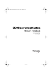
FIG. 7 shows a ?ow diagram for the program used by
wise. This line is buffered by two inverters 553 and 557
in series to avoid more then a single 'ITL load on the 65 the computer to process the bit stream from the card
reader. At block 701, the computer displays the prompt
computer line driver. The card reader and alarm status
operation, it is possible for them to inadvertently disarm
signals are not three state and must therefore be buff
ered before placing them on the internal data bus 503.
for the user to insert his card. Control passes to block
703 where the data at location BSzFFl is read and bit 3
13
4,951,249
14
is checked for a logic 1 which means that the card has
been inserted. If bit 3 does not equal a logic 1, the cycle
is repeated until it does equal a logic 1. If bit 3 does
equal a logic 1, control passes to block 705 where the
computer displays a prompt for the user to remove his
card. Control then passes to block 707 where the data at
BSzFFl is read and bit 3 is checked for a logic 0 which
means that the card is being removed. Control then
logic 0 on line 811 ‘and setting flip-flop 813. The “Q"
output of ?ip-?op 813 on line 833 goes high thus provid
ing the “alarm enable” signal. The disarm signal is gen
erated by two input AND gate 815 having the “alarm
control" signal coupled to one input by line 803 and line
A2 coupled to the other by line 805. When both the“a
passes to block 709 in which a “timeout” counter is
817 to conduct placing a logic 0 on line 819 and reset
started. Control passes to block 711 in which the data at
BSzFFl is read and bit 1 is checked for a logic 1 which
ting ?ip-?op 813. The “alarm enable” signal on line 833
means that the clock signal is high. If the clock signal is
not high, (bit 1 is not a logic 1) control passes to block
713 in which the timeout timer is checked. If the prede
termined period of time has not elapsed control passes
back to block 711 and the process is repeated. If the
predetermine period of time has elapsed control passes
to block 723. If the clock is high (bit 1 equals a logic 1)
control passes to block 715 and bit 2 (the data bit) is
larm control” signal and the signal on line A2 are high,
the output of gate 815 will be high causing transistor
will become a logic 0 and the alarm will become dis
abled.
In the armed state, the alarm will be triggered when
any of the normally open alarm switches 823 are closed
either by tilting the computer system or by attempting
to loosen the screws which enable access to the interior
of the computer hardware. These switches 823 connect
one of the inputs of gate 827 to ground via line 825. This
causes its output to go low. The low signal on line 829
stored. Control then passes to block 717 in which the 20 provides a set to ?ip-?op 831 which causes the "Q"
timeout counter is restarted after which control is
output of the ?ip-?op 831 to go high thus providing an
“alarm on" signal on line 841. This signal is ANDed
passed to block 719. In block 719 the data at BS:FF1 is
with the “alarm enable” signal on line 833 by gate 843.
read and bit 1 is checked for logic 0 which means the
If both signals are high, a high signal appears on line 845
clock is low. If bit 1 is equal to a logic 0, control passes
back to block 709 and this portion of the process is 25 which causes transistor 847 to conduct thus providing
power to oscillator 851 via line 849. Oscillator 851
repeated. If bit 1 is not a logic 0, control passes to block
drives a speaker or buzzer 853 to provide an audible
721 which checks the timeout counter. If the amount of
warning. Flip-flop 831 is reset by the signal on line 811.
time allowed for this operation has not occurred, con
The “alarm status" signal on line 839 is provided by
trol will pass via the “not timeout” branch back to block
buffer ampli?er 837 and resistor 835 which is coupled to
719 and the process will be repeated. If the amount of
line 833. This signal is provided to line 561 in FIG. 5.
time has elapsed control will pass to block 723.
The alarm system is powered by a nine volt battery so
In block 723, the program searches for the data bit
that the alarm enable and trigger states are not changed
stream stored in the random access memory for the start
sentinal bit which contains the bit pattern 01011. If that
by turning the computer on or off. In addition, this
bit pattern is not found, control passes to block 729 and 35 separate source of power provides an audible alert sig
nal even when the computer is in the off state.
an error message is displayed and the program passes to
While a particular embodiment of the present inven
its exit at block 731. If the start sentinal is found, control
tion has been disclosed herein, certain changes and
modi?cations will readily occur for those skilled in the
into ASCII code using a binary coded decimal four bit
character con?guration shown in Table l of the above 40 art. For example. a voice imprinter, electronic thumb
print scanner or optical bar code scanner can be substi
referenced American National Standard. The program
tuted for the magnetic card reader used the non-key
continues in this loop until the end of the bit stream is
board entry device which identi?es the user. All such
reached at which time the program exits at block 731.
changes and modi?cations can be made without depart
The resulting ASCII stream is used as a key to the
authorization file stored on the disk to determine if the 45 ing from the invention as de?ned by the appended
claims.
person placing the card through the reader is an autho
We claim:
rized user of the system.
1. A security device for a computer system having a
Referring to FIG. 8, the alarm circuit for the com
keyboard entry device and a floppy disc drive, compris
puter security system is generally shown as 800. This
circuit utilizes CMQS integrated circuits to provide a
ing:
(a) means for transferring control of said computer
low quiessent current drain because the entire alarm
system to a security system interposed between an
circuit is powered by a nine volt DC battery. The audio
operating system and all peripheral devices and
alarm 853 is a commercially available buzzer driven by
application programs and data stored in said com
oscillator 851 which is powered by the same nine volt
puter system;
battery. The alarm is activated by switching transistor 55
(b) means under control of said security system for
847 which is controlled by AND gate 843 which has a
changing the computer system's keyboard address
nine volt output whenever the “alarm enable” signal
to an address in the security system;
833 and the “alarm on" signal 841 are both in the logic
(c) means under control of said security system for
1 state.
changing the computer system's ?oppy disc drive
The alarm system is armed by software instructions in
passes to block 725 and the next ?ve bits are converted
the menu program which addresses location BS:0FFF2
and disarmed by addressing location BSzOFF4, where
“BS” represents the general address of the security
system circuit board. The “alarm enable" signal is gen
erated by ANDing line Al in gate 807 via line 801 with 65
the “alarm control" signal via line 803. When both of
these signals are high, the output of gate 807 will be
high causing transistor 809 to conduct thus placing a
address to an address in the security system;
(d) means at said address in said security system for
said ?oppy disc drive for blocking any input to the
computer system from said ?oppy disc drive which
would place the operation of the computer system
outside the control of said security system;
(e) means at said address in said security system for
blocking any keyboard input to the computer sys
15
4,951,249
puter system outside the control of said security
system;
(0 identifying means for identifying all operators of
said computer system;
floppy disc drive to an address in the security sys
(g) means for validating the operator’s identi?cation;
(it) means responsive to validation by said validation
means for restoring the address for said keyboard
to said computer system’s keyboard address;
(i) means responsive to validation by said validation O
means for restoring the address for said ?oppy disc
drive to said computer system’s ?oppy disc drive
address; and
(j) means for allowing said validated operator access
to only one or more of said programs and data and
16
place the operation of the computer outside the
control of said security system;
(d) changing the computer systems address for said
tern which would place the operation of the com
5
tem;
(e) providing at said security system address for said
floppy disc drive a routine for blocking any input
from said ?oppy disc drive which would place the
computer outside the control of said security sys
tem; and
(f) requiring all operators to identify themselves;
(g) validating the operator’s identi?cation;
(h) in response to validation, restoring the address for
said keyboard to said computer system’s keyboard
address;
operating system for which said validated operator
has been pre-authorized.
2. The security device according to claim 1, wherein
(i) in response to validation, restoring the address for
said floppy disc drive to said computer system’s
address for said floppy disc drive; and
said system includes a display, and wherein said means
for allowing includes means for displaying on said dis
play a menu of programs and functions which the user
(j) allowing a valid user access only to one or more of
3. The security device according to claim 1, wherein
said programs and data and operating system for
which the user has been pre-authorized.
9. The method according to claim 8, wherein said
system includes a display, and wherein said step (j)
said means for transferring includes a read only memory
includes displaying on said display a menu of programs
(ROM) read by said operating system and which con
tains instructions transferring control of the computer
system to the security program.
4. The security device according to claim 3, further
and functions for which the user is pre-authorized.
10. The method according to claim 9, further com
is authorized to use.
comprising:
means under control of said security system for
prising the following steps prior to step (a):
initiating operation of said computer system via the
30
operating system’s startup routine; and
reading a read only memory (ROM) containing in
changing the computer system’s address for DOS
structions for the operating system to transfer con
trol to said security system.
11. The method according to claim 10, and further
function call routines to an address in the security
system; and
means at said address in said security system for said
comprising:
DOS function call routines for blocking execution
of DOS commands unless said validated operator is
changing the computer system’s address for the criti
pre-authorized for said operating system.
tem; and
providing at said security system address for said
cal error routine to an address in the security sys
5. The security device according to claim 3, further
comprising:
critical errors a routine for blocking access to said
operating system.
means under control of said security system for
12. The method according to claim 10, and further
changing the computer system’s address for the
comprising:
critical error routine to an address in the security
changing the computer system’s address for DOS
system; and
means at said address in said security system for said 45
critical errors for blocking access to the operating
system.
6. The security device of claim 1, further comprising
a non-keyboard data entry device, and wherein said
means for identifying all operators of said computer
system comprises means for identifying all operators of
said computer system via said non-keyboard device.
7. The security device according to claim 6, wherein
said non-keyboard data entry device is a magnetic card
function call routines to an address in the security
system; and
providing at said security system address for said
DOS function call routines a routine for blocking
access to said operating system unless said valid
user is pre-authorized for said operating system.
13. The method of claim 8, wherein said computer
system further comprises a non-keyboard entry device,
and wherein said step (t) comprises requiring all opera
tors to identify themselves via said non-keyboard de
reader.
55
8. A method for securing a computer system having a
keyboard entry device and a ?oppy disc drive, compris
ing the steps of:
(a) transferring control of said computer system to a
vice.
14. The method according to claim 13, wherein said
non-keyboard data entry device reads a magnetically
encoded card in step (f).
15. A security device for a computer system having a
keyboard entry device, comprising:
security system interposed between an operating
system and all peripheral devices and application
(a) means for transferring control of said computer
programs and data stored in said computer system,
system to a security system interposed between an
said security system performing the following
steps:
(b) changing the computer system’s keyboard address
operating system and all peripheral devices and
to an address in the security system;
(c) providing at said security system address a routine
for blocking any keyboard input which would
application programs and data stored in said com
65
puter system;
(b) means under control of said security system for
changing the computer system's keyboard address
to an address in the security system;
17
4,951,249
(c) means at said address in said security system for
18
(c) providing at said security system address a routine
blocking any keyboard input to the computer sys
for blocking any keyboard input which would
place the operation of the computer outside the
control of said security system;
(d) requiring all operators to identify themselves;
tem which would place the operation of the com
puter system outside the control of said security
system;
(d) identifying means for identifying all operators of
said computer system;
(e) means for validating the operator’s identi?cation;
(e) validating the operator’s identi?cation;
(f) in response to validation, restoring the address for
said keyboard to said computer system’s keyboard
(f) means responsive to validation by said validation
means for restoring the address for said keyboard
address;
(g) allowing a valid user access only to one or more of
to said computer system’s keyboard address;
(g) means for allowing said validated operator access
said programs and data and operating system for
which the user has been pre-authorized;
to only one or more of said programs and data and
(h) changing the computer system’s address for the
operating system for which said validated operator
has been pre-authorized;
(h) means under control of said security system for
changing the computer system’s address for the
critical error routine to an address in the security
system; and
(i) providing at said security system address for said
critical errors a routine for blocking access to said
operating system.
critical error routine to an address in the security
system; and
22. The method according to claim 21, wherein said
(i) means at said address in said security system for 20 computer system includes a floppy disc drive, and
said critical errors for blocking access to the oper
wherein said security system further performs steps of:
changing the computer systems address for said
ating system.
16. The security device according to claim 15,
?oppy disc drive to an address in the security sys
tem;
providing at said security system address for said
on said display a menu of programs and functions which
floppy disc drive a routine for blocking any input
the user is authorized to use.
from said ?oppy disc drive which would place the
17. The security device according to claim 15,
computer outside the control of said security sys
wherein said means for transferring includes a read only
tem; and
memory (ROM) read by said operating system and 30 in response to validation, restoring the address for
which contains instructions transferring control of the
said floppy disc drive to said computer system’s
computer system to the security program.
address for said ?oppy disc drive.
18. The security device according to claim 17, further
23. The method according to claim 21, wherein said
comprising:
system includes a display, and wherein said step (g)
means under control of said security system for 35 includes displaying on said display a menu of programs
changing the computer system’s address for DOS
and functions for which the user is pre-authorized.
wherein said system includes a display, and wherein
said means for allowing includes means for displaying 25
function call routines to an address in the security
system; and
means at said address in said security system for said
DOS function call routines for blocking execution
of DOS commands unless said validated operator is
24. The method according to claim 21, further com
prising the following steps prior to step (a):
initiating operation of said computer system via the
operating system’s startup routine; and
reading a read only memory (ROM) containing in
pre-authorized for said operating system.
structions for the operating system to transfer con
19. The security device of claim 15, further compris
trol to said security system.
ing a non-keyboard data entry device, and wherein said
25. The method according to claim 21, and further
means for identifying all operators of said computer 45 comprising:
system comprises means for identifying all operators of
changing the computer system’s address for DOS
said computer system via said non-keyboard device.
20. The security device according to claim 19,
wherein said non-keyboard data entry device is a mag
netic card reader.
21. A method for securing a computer system having
function call routines to an address in the security
(a) transferring control of said computer system to a
system; and
providing at said security system address for said
DOS function call routines a routine for blocking
access to said operating system unless said valid
user is pre-authorized for said operating system.
26. The method of claim 21, wherein said computer
security system interposed between an operating
system and all peripheral devices and application
wherein said step (d) comprises requiring all operators
a keyboard entry device, comprising the steps of:
system further comprises a non-keyboard entry device,
progress and data stored in said computer system,
to identify themselves via said non-keyboard device.
27. The method according to claim 26, wherein said
non-keyboard data entry device reads a magnetically
encoded card in step (d).
said security system performing the following
steps:
(b) changing the computer system’s keyboard address
to an address in the security system;
i
65
t
i
i
i