1
IIIIIIIlllllllllllllllllllllillllllllIllllllllliillllllllIlllllllllllllllll
US005251622A
United. States Patent [191
[11] Patent Number:
Robson
[45]
[54] RESPONSIVE PACEMAKER WITH TIME
DOMAIN REFLECIOMETER AND
METHOD OF USE
[75] Inventor:
Jack R. Robson, Beech Grove, Ind.
[73] Assignee: Random Technologies, Inc.,
Indianapolis, Ind.
Date of Patent:
Cordis Corp. 1986 “What de These Pagers Have In
Common?”.
Tektronix 1502c Metallic Time Domain Reflectometer
Operator Manual May 1990.
Genesis ® Cardiac Pacing System Model 285 Techni- ‘
cal Manual Pacesetter Systems, Inc. 1985,
#9190420-001.
Automatic Implantable Cardioverter De?brillator‘ 1991
Nov. 4, 1992
Cardiac Pacemaker Inc.
[63]
Related US. Application Data
Continuation-in-part of Ser. No. 866,850, Apr. 10,
[51]
[52]
Int. Cl.5 ........................................... .. A61N 1/362
US. Cl. .......................................... .. 607/19
1992, Pat. No. 5,231,987.
[58] Field of Search
128/419 PG, 419 PT
[56]
References Cited
U.S. PATENT DOCUMENTS
Fuchs .................................. .. 73/290
4,466,288 8/1984 Grynberg et a1.
4,786,857 11/1988 Mohr et a1. ........ ..
...... .. 73/654
324/585 BO
4,843,234
7/1989
Berthold et al. .
..... .. 250/227
4,893,895
l/l990
Berthold et al. . . . . .
. . . .. 350/96
4,960,989 10/1990 Liebenrood et al.
5,033,826
7/1991
.. 250/227
Kolner .............................. .. 350/355
'
Hewlett-Packard Application Note 62, “TDR Funda
mentals” Apr. 1988.
Hewlett-Packard Application Note 62-1, “Improving
Time Domain Network Analysis Measurements”, Apr.
1988.
3,922,914 12/1975
Oct. 12, 1993
Ventek ® P AICD TM Model 1600 Physician’s Manual
[211 App]. No.: 971,281
[22] Filed:
5,251,622
"
Hewlett-Packard Application Note 62-3 “Advanced
TDR Techniques” May 1990.
Primary Examiner-William E. Kamrn
Attorney, Agent, or Firm-Baker & Daniels
[57]
ABSTRACT
Responsive heart stimulating device and method for
operating the device which includes a heart stimulating
waveform generator for transmitting a waveform to an
electrode. A time domain re?ectometer (TDR) is also
connectable to the electrode for generating TDR sig
nals. A logic and control unit processes TDR readings
from the electrode, and is adapted to alter the heart
OTHER PUBLICATIONS
Tektronix 1502c Metallic Time Domain Reflectometer
Service Manual Tektronix, Inc. Jul. 1991, pp. 5-1 to
5-11.
stimulating waveform in response to the TDR readings.
The TDR may be connected to a pacemaker pacing
electrode to detect changes in heart stroke volume or
cardiac output, or to one or more probes capable of
Physician's Model Models 253-25 and 254-30 Jan. 1990.
detecting motion of the patient, and the logic and con
trol unit may adjust the pacing rate accordingly.
Pacesetter® Technical Manual-APSII Model 3000
Programmer with Model 3030 Function 1988.
31 Claims, 7 Drawing Sheets
Quantum ®II, Intermedics Cardiac Pulse Generator
mam
moemmen
(
2e
20
‘8
2
19
)
12
J‘
1a
- 3
1
26
)
14
+
V
-
15
reuausrav
moeam
‘WE
OUTPUT
M5;
TRANSMITTER
nscervea
mm"
m
saicroal
‘___G/_
VOLTAGE
mm —+l]{_
_ 1e
—>] [case
w
25
mmmea
1)
[
IHEEJSWITOH [- 11“
\-17
ago-“lg
cavsm
Mum
LOGICANDOONTHOL
svsreu
~24
TDR
RFOSCILLATOFI
"0
CONTROL
EH
am
11011
l
)
l
l
22
21
i
~23
US. Patent
Oct. 12, 1993
Sheet 5 of 7
:Tl m0i2snE-3m.w
mow
bow
m2;
wow
mNmeEw<.m
mow
wow
5,251,622
US. Patent
Oct. 12, 1993
Sheet 6 of 7
5,251,622 '
,81?
our
.QQSN
Pup
%.mL“
US. Patent
Oct. 12, 1993
Sheet 7 of 7
,3
h
:2
.S
E
3.5
5,251,622
1
5,251,622
2
sensor, such as when performing bench presses with
heavy barbells. In such circumstances, no physical mo
tion will be detected so the pacemaker will not increase
the pacing rate, even though an increase would be ap
RESPONSIVE PACEMAKER WITH TIME
DOMAIN REFLECTOMETER AND METHOD OF
USE
propriate. In short, motion-based responsive pacemak
CROSS REFERENCE TO RELATED
ers can not distinguish between motions that relate to
APPLICATIONS
increased physical activity and those that do not. Fur
This is a continuation-in-part of application Ser. No.
07/866,850 ?led Apr. 10, 1992, now US. Pat. No.
thermore, if unnecessary pacing is activated by these
devices, battery power consumption results in a short
'
5,231,987.
10 ened battery life. Shortened battery life may require a
patient to undergo a surgical procedure to replace the
FIELD OF THE INVENTION
This invention relates to a device, system and method
used in medical equipment, and, in particular, to a re
battery sooner than may otherwise be required. It is also
desirable to develop a rate-responsive system that re
quires little power to operate so as to extend pacemaker
sponsive system for adjusting the waveform, such as the
pacing rate, ‘of a pacemaker in response to changes in
physiological activity of the user.
battery life.
Due to the shortcomings of motion-based rate re
sponsive sensors, other rate adjusting systems are re
sponsive to certain physiological conditions of a patient.
BACKGROUND OF THE INVENTION
Some pacemaker systems vary the pace rate based on
When a patient is provided with a pacemaker, the 20 changes in body temperature. These systems use a tem
I pacemaker may be designed to generate heart stimulat
perature sensing device such as a thermistor to sample
ing pulses continually, or only when the patient’s natu
the temperature of the body. The thermistor is built into
ral heart rate falls below a predetermined rate or (inter
an electrode of the pacemaker. The resistance of the
nal) threshold. In either case, the generated pulses will
thermistor varies as a function of temperature so that
occur at a predetermined rate (the “pace rate.”) In addi 25 the device can generate an electrical signal that corre
tion, some pacemakers are “rate responsive,” which
sponds to the sensed temperature. This signal may be
means that they automatically adjust the pace rate if the
translated into a pro-programmed activity level used to
patient’s suspected physical activity increases or de
set the pace rate.
creases. They are many different systems used in pace
makers to predict when a patient’s physical activity has
increased, and therefore, when the pacing rate should
30
However, body temperature sensitive systems also
result in many of the problems that occur in motion
sensitive rate-responsive systems as changes in body
be increased.
Several systems for varying the pacing rate of a pace
maker work on the assumption that increased physical
temperature may occur without regard to physical ac
tivity. Thus, the system may attempt to ?lter out such
motion means that the patient is engaging in physical 35 extraneous temperature changes. Yet, such a ?ltering
system poses the risk that changes in temperature that
should be used to vary the pacing rate will be ignored.
Further, because the thermistor is built into a special
ized electrode, that electrode can only be used with a
activity, and that the pacing rate must therefore be
increased. For example, the Elite TM Models 7074,
7075, 7076, and 7077 manufactured by Medtronic, Inc.
of Minneapolis, Minn, may be programmed to vary the
pacing rate in response to detected changes in body
pacemaker sold by a particular manufacture, thereby
limiting the physician’s and patient’s choice of pace
motion. A sensor within the device, typically a piezo
electric crystal placed on the inside wall of the pace
makers. Due to cost and insurance regulations, it is not
maker, detects pressure waves within the body caused
by body motion. The device then converts these pres
sure waves into electrical signals. The pacing rate is set 45
normally feasible to replace a previously implanted
electrode or pacemaker. Thus, temperature responsive
systems have the shortcomings of being poor predictors
of a change in physiological activity, and of having only
in proportion to the frequency and amplitude of these
a limited choice of pacemakers from which to select.
electrical signals. Other systems, such as the Relay TM
Other systems, referred to as QT systems, adjust the
Models 293-03 and 294-03 manufactured by Interme
' pace rate by determining the activity level as measured
dics, Inc. of Freeport, Tex., use an accelerometer in
stead of a piezoelectric crystal to detect physical mo 50 by the QT interval measurement; that is, the time be
tween when a pacing pulse is sent to the heart and the
tion. The accelerometer computes acceleration by mea
time the QT interval of the heartbeat begins. Generally,
suring the force exerted by restraints that hold a mass in
as a patient’s physical activity increases, the heart re
a ?xed position. The accelerometer may either be elec
sponds more quickly to a pacing pulse. Therefore, QT
trically excited or self-generating, using a piezoelectric
' crystal as discussed above. Some systems also include 55 systems increase the pacing rate when they sense that
this time period is reduced. A particular shortcoming of
multiple accelerometers oriented in different axes, so
QT systems is that in order to sense when pacing should
that movement in different directions can be discerned
be initiated or increased, they must actually send a pac
and used to reduce to obtain are more accurate indica
_ tion of the extent of physical movement.
However, the theory behind motion sensitive rate
responsive systems is fundamentally flawed because
physical motion does not necessarily mean that a pa
tient’s physical activity has increased. For example,
motion-based responsive systems will increase the pac
ing rate when a patient is driving down a bumpy road,
even though there is no increase in physical activity.
Likewise, a patient may undertake signi?cant physical
activity that does not involve movement of the motion
ing pulse to the heart, regardless of the patient’s intrin
sic heart rat'e. In general, it is medically undesirable to
send pacing pulses to the heart unless it is known that
the heart actually requires a pulse. In addition, unneces
sary pulses also needlessly consume battery power.
Another type of rate-responsive system is based on
65 measuring a patient’s blood oxygen saturation levels.
These systems assume that when a patient increases
physical activity, there is a corresponding increase in
the blood oxygen saturations level. These systems em
3
5,251,622
ploy special electrodes equipped with a light emitting
diode (“LED”) and a phototransistor which measures
the occlusion or blockage between the two. This block
age roughly corresponds to the amount of oxygen in the
blood tissue. While the device is based on a physiolog
ical phenomenon, it has two drawbacks. First, the LED
require a signi?cant amount of power which reduces
4
which is not dependent upon the critical placement of
multipolar specialized electrode. It is also desirable to
provide a rate-responsive system which works in con
junction with both endocardial and epicardial lead sys
tems.
OBJECTS OF THE INVENTION
the life of the battery powering the pacemaker. Addi
tionally, the system requires special electrodes that may
lock the physician into the selection of a particular
system.
Accordingly, it is one object of the present invention
to provide a method to adjust the pacing rate of the
pacemaker in response to physical activity level of the
Rate-responsive systems are also available which
depend upon a patient’s respiration to alter the pacing
rate. These systems assume that increased air volume in
It is another object of the present invention to pro
vide a system that measures the physical activity level
of the user through a physiological phenomenon to
avoid generating unnecessary pacing signals.
'
It is another object of the present invention to pro
vide a pacing system that requires little power to oper
the lungs means a patient is breathing deeper, suggest
ing that the patient is engaged in increased physical
activity. Alt et al., "Function and Selection of Sensors
for Optimum Rate-Modulated Pacing,” New Perspec
patient.
ate.
tives In Cardiac Pacing, ed. Barold et al., 1991, p.
It is still another object of the present invention to
189-196. Speci?cally,‘ such a system measures the respi 20 provide a pacing system that may use universal elec
ratory rate by detecting the electrical impedance be
tween an auxiliary electrode lead and the pacemaker
can. Because the electrical conductivity of lung tissue
trodes to insure user ?exibility.
It is yet another object of the present invention to
provide a pacing system which operates with both en
decreases with inspiration, breathing can be detected by
docardial and epicardial lead systems.
monitoring changes in electrical resistance. The resis 25 It is yet another object of the invention to provide a
tance can be measured between different points within
pacing system that can also determine the physical and
the system. One can apply a current between the pace
electrical integrity of the pacing electrode.
maker can and an anodal ring of a bipolar electrode so
It is yet another object of the invention to provide a
that the system measures the resistance change between
responsive
pacing system that is responsive to heart
the pacemaker can and the tip of the bipolar electrode. 30
stroke volume, cardiac output, physical motion, or any
However, one disadvantage of these respiration sys
combination of the foregoing.
tems is their sensitivity to movement. For example, a
respiration-dependent system is likely to detect high
BRIEF DESCRIPTION OF THE DRAWINGS
impedance changes if the pacemaker user moves his
arms or has chest movements. Such measurements may 35
be interpreted by the system as deep breaths that require
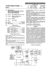
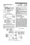
FIG. 1 shows a block diagram of one embodiment of
a device of the present invention when used in connec
an increased pace rate. Further, these system requires
tion with a programmable cardiacpacemaker.
bipolar electrodes as one wire is needed to emit an RF
wave and another wire is required to sense voltage.
interface for con?guring and testing an implantable
FIG. 2 a representative computer touch screen user
electrode according to the invention.
FIG. 3 is a representative computer screen list win
dow displaying an index of previous TDR readings
which have been stored in the device.
vidual increases physical activity, the stroke volume of
FIG. 4 is a representative computer screen list win
the heart increases, regardless of whether the heart rate
remains constant due to a condition such as chrono 45 dow displaying a partial index of electrode manufactur
ers and models, one of which may be selected to pro
tropic incompetence. To measure stroke volume a spe
vide a set of default electrode, sampling and display
cialized electrode having two or more electrode poles is
options
for a particular electrode.
positioned with the right ventricle. These impedance
FIG. 5 is a representative graphically displayed base
based rate-responsive systems transmit a low-amplitude
line TDR reading for an electrode in good condition.
AC pulse or short intermittent electrical pulses to the
FIG. 6 is a representative graphically displayed base
multipolar electrode to measure resistance between the
line TDR reading having superimposed over it a more
electrode poles. As resistance is affected by the amount
recent TDR reading for the same electrode showing
of blood between the electrode poles, stroke volume is
Yet another type of rate-responsive pacemaker is
based on the determination of changes in the stroke
volume of the heart. Alt et al., p. 172-177. As an indi
that a break has occurred in the electrode and that the
estimated. The pacing rate is increased when an in
crease in heart stroke volume is detected. However, 55 electrode is now defective.
these systems also have limitations. First, only a portion
of the stroke volume may be measured as the measure
FIG. 7 is a representative graphically displayed TDR
reading for an electrode have a short in it.
FIG. 8 is a representative time graph showing the
trailing end of a stimulating pulse on the electrode, a
pairs. Also, a multipolar rather than a unipolar elec
trode is required and the electrode must be carefully 60 TDR incident pulse, and re?ective pulse.
FIGS. 9:: and 9b are views of a heart in which a
placed into position. Furthermore, stroke volume may
pacemaker is implanted in which the heart is at its re
only be measured for endocardial lead systems, i.e.,
spective minimum and maximum stroke volumes.
those residing within the heart, but not for epicardial
FIGS. 10a and 10b are representative TDR readings
lead systems. Therefore, selection of a pacemaker that
ments are dependent upon the position of the electrode
uses a specialized electrode is limited. Though stroke 65 from an electrode taken at times when the heart is at its
respective minimum and maximum stroke volumes.
volume is a physiological phenomenon which accu
FIGS. 11 and 12 are side and top sectional views,
rately re?ects the pacing requirements, it is desirable to
respectively, of an enclosed chamber having liquid and
provide a rate-responsive system using stroke volume
2,
5,251,622
5
6
component.
(typically by a tunnel diode) to the electrode and moni
tors the resulting re?ected voltage on the electrode
FIGS. 13-15 are representative TDR readings from
the TDR probes in FIGS. 11 and 12.
over a period of time. A stored re?ected voltage wave
form comprises a raw TDR reading. If the electrode has
TDR probes therein, and which acts as a motion sensor
a known propagation velocity (Vp), the time delay to a
particular re?ection may be interpreted in distance from
the pulse generator. This would include the pacemak
er’s internal wiring to the pacing electrode connectors,
the electrical connection between the connectors and
the pacing electrode, and the entire length of the pacing
wire, terminating in the portion placed in heart tissue.
SUMMARY OF THE INVENTION
In one embodiment, the invention is a responsive
heart stimulating device and method for operating the
device which includes a heart stimulating waveform
generator for transmitting a waveform to an electrode.
A time domain re?ectometer (TDR) is also connectable
to the electrode for generating TDR signals. A logic
and control unit processes TDR readings from the elec
trode, and is adapted to alter the heart stimulating
waveform in response to the TDR readings. The TDR
may be connected to a pacemaker pacing electrode to
The amplitude of the re?ected voltage is a function of
the electrode impedance (admittance/conductance) and
the applied pulse, and therefore can be interpreted in
dB, or in millirho, which is a function of impedance.
Circuitry for time domain re?ectometers is well-known
and, in isolation, do not form the present invention. In
detect changes in heart stroke volume or cardiac out
general, a TDR comprises an I/O controller, a digital
put, or to one or more probes capable of detecting mo
timebase, an analog timebase, and a pulse generator. As
tion of the patient. One feature of the invention is that
because cardiac chemistry affects the cardiac substrate 20 described further below and shown in FIG. 8, the TDR
generates a short, fast rise time output pulse. After a
which increases or decreased how hard the heart mus
predetermined amount of time has passed (the TDR
cle contracts or relaxes, such changes can be detected
base time), the pulse as re?ected back by the wire/elec
and the a pulsing waveform may be modi?ed accord
trode is monitored. This comprises means for deferring
ingly.
25 the storing of the TDR signal until the amount time
DETAILED DESCRIPTION
speci?ed by the TDR base time signal has elapsed after
the generation of a TDR incident pulse. At a speci?c
Referring to FIG. 1, there is shown a representative
time, as determined by the digital timebase, a portion or
block diagram of one embodiment of the present inven
tion. In this embodiment, the invention is located in an
“slice” of the re?ected wave is stored in an analog
implantable multi-programmable pacemaker, which
30 timebase. This value is then converted to a digital value
includes logic and control unit 11 (which includes a
CPU and appropriate software to carry out the func
by an analog to digital converter and stored in memory.
tions described herein), rate limit section 12, and means
except that the time period between the pulse genera
for generating a heart stimulating waveform, namely
output section/voltage multiplier 13. Conventional mi
The pulse generating-wave storing process is repeated,
tion an when a portion of the re?ected wave is stored is
35 increased slightly, causing a different “slice” of the
crocircuitry, and preferably, and application speci?c
re?ected wave to be stored. After a suf?cient number of
integrated circuit, is used to package the TDR and
other components in the implantable case. The pace
maker is designed to provide periodic pulse to two
samples (e. g., 256) have been collected, a compilation of
the stored waveform readings (a “TDR reading”) pro
implantable pacing electrodes through electrode receiv
vides a view of the entire re?ected wave. A representa
40 tive TDR pulse may comprise a 300 mV amplitude into
ing means, namely connectors 14 and 15, and 16 and 17
respectively. However, the invention may also be used
with a device connected to a single electrode. Con
nected to logic and control unit 11 is a telemetry system
a 50 ohm load, with a 25 microsecond pulse duration,
and the re?ected rise may be detected in less than 200
picoseconds.
In general, the present invention operates in the fol
comprised of telemetry transmitter 18 and program 45 lowing manner. Logic and control 11 is designed to
periodically send pacing signals via output line 24 to
receiver 19, both of which on connected to common
output section/voltage multiplier 13. Logic and control
antenna 20. The telemetry system allows the pacemaker
section 11 is programmed to cause output section/volt
to be interrogated to determine its operating conditions
age multiplier to generate cardiac stimulating pulses of
after it has been implanted, and also allows the pace
maker to be reprogrammed without surgery. For exam 50 predetermined amplitude, duration and frequency ac
ple, the device can be reprogrammed to generate stimu
cording to parameters stored in RAM 22. A typical
lating pulses on the pacing electrode at set rate, or at a
cardiac pacemaker generates stimulating pulses at fre
quencies of 0.5 to 3 per second, at amplitudes from 2.5
varying rate depending on cardiac activity. Other pa
V to 8.5 V, and at durations of 0.15 to 2.3 milliseconds.
rameters, such as the pulse width and pulse amplitude
can also be speci?ed after the pacemaker has been im 55 Accordingly there is a substantial time gap of at least
300 milliseconds between pulses. As a complete TDR
planted. These operating parameters are stored in ran
pulse and re?ection reading'time can be accomplished
dom access memory (RAM) 22, while the control pro
with a pulse repetition rate of 200 microseconds, it-is
gram is stored in read only memory (ROM) 21. Repro
possible to take an entire set of 256 readings in well
gramming is accomplished through the use of an exter
under 60 milliseconds. Thus a complete TDR reading
nal system programmer 28 having an RF transceiver
can be generated between the stimulating pulses period
wand 27, although a convention serial data port with
ically provided to the pacing electrode. However, it is
lead connectors extending through the skin of the pa
tient may also be used.
‘
The invention also includes time domain re?ectome
also within the scope of the invention to space out the
TDR pulses between multiple stimulating pulses.
and to detect the resulting re?ected voltage. A TDR
Prior to implantation of the device in body, the de
vice will be programmed with various default parame
ters. Conventional pacemakers are programmed, for
applies a narrow pulse of current with a fast rise time
example to specify the stimulating pulse repetition rate,
ter (T DR) l/O control 23, which includes the circuitry 65
necessary to generate a TDR pulse on the electrodes
7
5,251,622
pulse amplitude, positive and negative sensitivities and
control mode. Prior to implantation, one or more pac
ing electrodes will be selected and connected to pacing
leads 14, 15 and 16, 17 of the pacemaker. Each model of
electrode has its own characteristics, including‘a textual
model number, polarity, number of ?laments, electrical
length, physical length, Vp and source resistance. Rep
resentative electrode parameters to assist in taking later
TDR readings, are shown as electrode menu options 40
in FIG. 2. In addition, each electrode will ideally have
a set of default sampling 41 and display 42 options.
Preferably, the electrode parameters, sampling and dis
play options may be speci?ed by the electrode manufac
turer and used to set default values in the pacemaker
prior to implantation. Storing these parameters into the
_ pacemaker is accomplished using conventional teleme
8
the physician desire to change any of the default values,
the physician may repeatedly depress the down arrow
until the value to be changed is highlighted. The physi
cian may then depress the left 48 and/or right 49 ar
rows, which will cause the highlighted values to be
decremented or incremented, respectively.
After the physician has speci?ed the desired elec
trode con?guration values, the physician may store
them in the pacemaker so that they do not have to be
reprogrammed each time a TDR reading is taken. This
is done by depressing the up or down arrows until the
“Store Con?guration to Pacemaker” option is selected.
The Select button is then depressed, which causes all of
the displayed electrode information to be transmitted to
the pacemaker by RF transceiver 27 and stored in RAM
22. If the pacemaker provides means for connecting to
try programming equipment with appropriate software
a second electrode or wire, such as for multiple leads, or
to carry out the functions described herein.
includes two leads for single bipolar electrode (i.e. a
pulse/cathode and a ground/anode) then the pace
To program the default electrode, sampling and dis
play options into the pacemaker, external programmer 20 maker RAM 22 may be con?gured with suf?cient mem
ory to store a separate setting for each electrode or lead.
28 is ?rst turned on, and the telemetry head of wand
(It should also be noted that a singe electrode can com
antenna 27 is positioned over the pacemaker. The telem
prise a multi-?lament wire.) In addition, pulse selector
etry head generates a magnetic ?eld which activates
will include switch means for selecting whether the
reed switch 25 inside the pacemaker. This switch causes
logic and control unit 11 to activate program receiver 25 time domain re?ectometer is operably connected to the
means for connecting the ?rst implantable electrode or
19 and to receive instructions from programmer 28. In
one embodiment of the invention, programmer 28 has a , the means for connecting to the second implantable
electrode. The location for each storage will be desig
touch screen and various options are selected by touch
nated by the “Electrode No.” option in FIG. 2. If a
ing the indicated portion of the screen. The physician
will initially step through the prompts displayed on
pacemaker having capability for storing only one set of
programmer 28 to transmit the desired pacemaker set
tings (e.g. stimulation rate, pulse amplitudes, sensitivi
electrode readings receives an instruction and data to
store electrode settings for an electrode other than no.
ties and mode) into the pacemaker. The physician may
1, the number information may be ignored and the val
ues replaced by the received values.
then select a TDR option on programmer 28, which
will cause programmer 28 permit the TDR parameters 35 After this information has been speci?ed, and prior to
to be specified and displayed, such as through the TDR
options screen shown in FIG. 2.
The physician will initially wish to specify the default
TDR values to be stored in the pacemaker. Ideally,
implantation, the physician may take an initial TDR
reading. This is done by using the up and down arrows
to highlight the “Obtain TDR Reading” option, the
depressing the Select option 50 on the touch screen.
programmer 28 will include a database of electrode 40 This action .causes programmer 28 to transmit a com
mand to the pacemaker commanding the pacemaker to
manufacturers and models, with default electrode, sam
pling and display options for each electrode model. The
database may be periodically updated by programmer
28 manufacturer via a ?oppy disk with information
concerning new electrodes on the market. When the
physician ?rst enters the TDR menu, the top “Read
Con?guration for Pacemaker” option will be high
lighted in reverse video. To select a default electrode
con?guration from the database, the physician presses
down arrow 43 to cause the “Select Con?guration from
Electrode Database" option to be highlighted. The
physician then depresses the Select button 50 on the
screen. This causes an overlapping window to be dis
played on the screen as shown in FIG. 4, displaying a
list of electrode manufacturers and model numbers. The
physician may repeatedly depress the down arrow until
the electrode to be implanted is'highlighted, then de
press the Select option 50 on the touch screen. This will
take a TDR reading according to the parameters stored
in RAM 22.
When the pacemaker receives an instruction to take a
TDR reading, the pacemaker waits until no stimulating
pulse is present on the electrode. Referring to FIG. 8,
normally, if stimulating pulses are being generated on a
periodic basis, logic and control unit 11 will wait until
the trailing edge of stimulating pulse 101 has been gen
erated. Because stimulating pulse 101 may cause noise
to be present on the electrode for a short time period
after the pulse is generated, no action is taken during the
time previously speci?ed as TDR Blanking Interval
103. This system comprises means for deferring genera
tion of the TDR incident pulse until the amount of time
specified by the TDR blanking interval has elapsed
after the transmission of a stimulating pulse on the elec
trode, or the detection of 'an identi?ed physiological
event. For stimulating pulse electrodes, this allows volt
close the display window, and cause the Electrode,
Sampling and Display options to be set to the default 60 age on the electrode to completely drain until the TDR
reading process begins. Also, some sensing electrodes,
values recorded in the database for the particular elec
such as those used to monitor heart activity, may have
trode. While in this window (or any other window
a rhythmic voltage on them generated by an internal
which may be opened) at any time prior to depressing
the Select option 50, the physician may depress the
Escape 47 portion on the screen, which will close the
window and cause the display to revert to its previous
status. A representative window and set of electrode
default information values is shown in FIG. 1. Should
organ. Such electrodes are used, for example, to moni
tor cardiac activity, and logic and control unite 11 sec
tion of the pacemaker is capable of determining, at any
point in time, the status of the rhythmic activity. For
such electrodes, it is desirable to time each TDR read
9
5,251,622
10
After the TDR reading has been generated, logic and
ing to begin at the same time in the rhythmic cycle so
that each TDR reading is taken at the same time of the
control section 11 sends a signal to pulse selector 26
causing the electrode connectors 14, 15 and/or 16, 17 to
rhythmic cycle, and therefore less subject to noise. For
a cardiac sensing electrode, TDR blanking interval 103
may begin after completing of physiological event such
_ last for 300 milliseconds. After the 300 millisecond
be electrically reconnected to the output section 13, and
electrically disconnected from TDR I/O 23. The isola
tion of TDR I/O 23 from output section 13 by pulse
selector 26 guards against any damage to the circuitry
blanking interval, the TDR reading (or readings) may
of TDR I/O 23 from stimulating pulses generated by
be made, as further described below, and the readings
may be completed before the ventricular beat begins.
output section 13. Thereafter, the generation of stimu- '
as the atrial beat, as sensed by logic and control 11, and
lating pulses may resume.
If the number of readings averaged parameter is
greater than one, then the TDR reading process may be
repeated, either immediately, if the time until the next
stimulating pulse to be generated is suf?ciently long, or
else after the next stimulating pulse is generated. Taking
This method, in combination of the minimal current
needed to generate a TDR incident pulse, minimizes the
likelihood of causing an irregular heartbeat. This system
constitutes an anti-coincidence detector adapted to pre
vent a stimulating signal or physiological event from
interfering with the incident pulse signal generated by
multiple TDR readings and averaging them reduces .
any noise that may be inherent in a single reading. For
the time domain re?ectometer and its re?ected wave.
averaged readings, instead of storing the each set of
After the TDR blanking interval has passed, logic
individual TDR waveform readings to the same RAM
unit 26, which causes the electrode leads to be switched 20 address, the digital values may be added to the previ
ously stored values. After the total number of TDR
from an electrical connection with output section 13 to
readings speci?ed by the “No. of Readings Averaged”
the TDR I/O and control section 23. (During normal
parameter has been completed, the each sum may be
pacemaker operation, TDR I/O and control 23 is insu
and control system 11 sends an signal to pulse selector
lated by pulse selector 26 from the stimulating pulses, to
minimize the possibility that the relatively large cur
rents and voltages of the stimulating pulses will harm
the TDR circuitry. Also, as described below, pulse
divided by the number of readings comprising the sum
25 to obtain a composite reading, namely the average.
Alternatively, it is envisioned that merely the raw TDR
readings may be transmitted to programmer 28 as de
scribed below, and programmer 28 perform the averag
selector unit 26 may also operably connect TDR 23
ing of the readings.
with either X 134, Y 135 or Z 136 motion axis probes.)
Logic and control 11 then sends a signal to TDR I/O 30 It will be appreciated from the description of the
foregoing embodiment that the time domain re?ectome
and control 23, which comprises means for transmitting
ter, i.e. the system for generating incident pulses and
an electrical signal to the electrode receiving means,
storing the re?ected wave form, comprises a logic and
commanding the TDR to generate an incident pulse 104
control system as is already found in conventional pace
(see FIG. 8) on the selected electrode lead.
In one embodiment of the invention, logic and con 35 mekersyas well as TDR I/O circuitry. Moreover, a
break in an electrode can also be detected merely by
trol section 11 may include in the signal it sends to TDR
measuring the time interval between the beginning of
I/O 23 a signal representing a impedance through
which the TDR pulse should be sent. Ideally, the impe
dance equals the impedance of the electrode. Accord
the incident pulse and the beginning of the re?ected
waveform.
ingly, TDR I/O 23 may include an internal array of
source resistors of various impedances through which
an incident pulse may be transmitted, and be connected
to a multiplexer to select which resistor the pulse
should be transmitted. This provides a preferred TDR
45
re?ection waveform.
After the raw or composite TDR reading has been
stored in RAM 22, logic and control section 11 trans
mits the stored raw or composite waveform through
TDR reading output signal means, such as transceiver
means comprised 'of telemetry transmitter 18 and an
tenna 20, to wand 27 of programmer 28. In addition, in
After generation of incident pulse 104, TDR l/O
the preferred embodiment, logic and control section 11,
waits the amount of time represented by TDR Base time
105. Normally, this amount of time will be selected to
will also transmit to programmer 28, the stored sam
pling values used to take the TDR reading to program
represent the amount of time it will take for a re?ected
mer 28. This transmission assures that the correct pa
pulse to be detected by TDR I/O 23, and may be on the
order of l—l0,000 nanoseconds, depending on the elec
trical characteristics and length of the electrode. After
TDR Base Time 105 passes, the TDR stores analog
voltage detected 106 on the electrode in an analog time
base. Voltage 106 represents only a small portion of the
entire re?ected waveform 107. This analog voltage
value is then converted to digital format by an analog
to-digital converter in TDR I/O 23, and then transmit
ted to logic and control section 11 for storage in output
device, such as RAM 22. After a predetermined amount
rameter values may be displayed in association with the
TDR reading. Programmer 28 then displays the re
ceived TDR reading in graphical form on a monitor (in
graphical display window 411) or a printer, or both.
Preferably, programmer 28 includes a Print button
which when depressed, causes the displayed graph, and
current con?guration information to be printed. A rep
resentative TDR waveform for a working electrode is
shown in FIG. 7. The horizontal axis represents the
time, or sequential samples of the TDR reading, which
can be directly converted into electrode distance if the
VP of the electrode is known. As discussed above, this
information may be supplied by the electrode manufac
turer or manually programmed into the programmer.
With a known VP. the vertical gridlines, or divisions,
voltage reading is stored in the analog timebase is incre 65 represent a speci?c length from the TDR I/O output to
the end of the electrode. The vertical axis of the wave
mented slightly with each cycle. As a result, RAM 22
form represents millirhos, which is directly convertible
has stored in it a raw TDR reading representing the
into impedance. Thus, a rise in the waveform represents
re?ected waveform.
of time, such as 200 microsecond from the initiation of
the ?rst incident pulse, TDR I/O 23 generates second
TDR pulse 108. The above process is repeated numer
ous (e.g. 256) times, except the time at which an analog
11
5,251,622
12
increased resistance along the electrode, while a fall in
the waveform represents a short circuit between the
maker and electrode. Following implantation, but prior
to closing the surgical incision in the patient, the physi
electrode and the pacemaker ground.
Accordingly, for the representative waveform shown
cian may take a second TDR reading to ensure that no
in FIG. 7, waveform rise 52 represents an increase in
implantation. Assuming the TDR reading is acceptable,
resistance, which in this representative case, is attributa
the physician may close the incision.
Following implantation, the patient can be expected
to have numerous follow-up visits with the physician,
damage to the pacemaker or electrode occurred during
ble to the internal pacemaker wiring connection be- ._
tween the application speci?c integrated circuit on
which pacemaker circuitry is connected and the wires
connected to the pacing leads 14, 15, and 16, and 17.
during which the integrity of the implanted electrode
l0 may be evaluated. This may be done using the same
Second waveform rise 53 is attributable to the intercon
programmer 28 described above. After the programmer
is turned on, wand 27 is positioned over the patient’s
pacemaker, and the TDR option is selected, the screen
stant impedance throughout the length of the electrode,
shown in FIG. 2 may appear. The physician choose to
with no breaks or shorts.
15 ?rst retrieve a copy of the archived TDR reading from
FIG. 5 shows a representative TDR reading in which
when the electrode was ?rst implanted. This may be
the electrode has a partial short and is in need of re
done by using up 44 and down 43 arrows to highlight
placement. Such a short may be caused, for example, by
the “Review Archived TDR Readings” option, and
defective insulation between the leads/wires of a bipo
depressing Select. This will cause programmer 28 to
lar electrode, or by the exterior insulation of the elec 20 send a signal to the pacemaker instructing logic and
trode becoming worn by, for example, excessive rub
control section 11 to transmit the archive number, date,
bing against a bone, pacemaker case or other structure.
comment and physician portions of each archived TDR
The short is evident by waveform fall 60, indicating the
reading to the programmer. An archived TDR display
impedance of the electrode at that point has fallen.
window, as shown in FIG. 3 is then displayed. Using up
At anytime while a TDR Reading is displayed, the 25 44 and down 43 arrows, the physician may highlight an
physician may depress the cursor left 45 or cursor right
archived TDR reading, which will normally be the
46 arrows below the display to cause graphical cursor
baseline reading or ?rst reading archived after implanta
48 to move left or right. At the point where cursor 48
tion. Depressing the Select portion of the screen causes
intersects waveform 49, the distanceof the electrode
programmer 28 close the window and to command the
circuit and impedance of the waveform are shown in 30 pacemaker to transmit the selected archived TDR read
displays 54 and 55. Thus, cursor 48 and displays 54 and
ing (including the electrode, sampling and display op
55 comprise means for superimposing a distance scale
tions) to the programmer, where they are displayed.
measurement corresponding to the length of the im
The physician may then depress the up arrow to high
planted electrode on the graphical display.
light the “Obtain TDR Reading” menu option, then
After the physician has obtained and displayed the 35 press Select 50. This will cause a TDR reading to be
composite TDR reading, the reading may be transmit
generated as described above, and superimposed over
ted back to the pacemaker and stored in RAM 22,
the archived TDR reading.
which comprises means for storing multiple TDR out
By highlighting and adjusting the “Max Mlllirho
put signals. As shown in FIG. 2, this may be done by
Alarm” option, the physician may specify a millirho
depressing the down arrow until the “Archive Current 40 value (predetermined threshold) by which, if a TDR
TDR Reading in Pacemaker” menu option is high
reading deviates in a relevant portion, an indicating
lighted. The Select button is then depressed. This causes
output warning signal, such as a ?ashing light, buzzer,
programmer 28 display a dialogue box on the screen in
or “DEFECTIVE” screen display is generated. High
which the physician may type a short descriptive sum
and low limits from the electrode portion of the display
mary of the reading using a keyboard connected to 45 waveform may be represented as horizontal lines on the
programmer 28, such as “Pre-implant readings w/Tech
graphical display. Speci?cally, minimum warning line
nitronics 1000”, and in which the physician may enter
64 and maximum warning line 65 as shown in FIG. 67
his or her name. After this option information has been
de?ne the boundaries in which the entire electrode
nection between electrode receptacle and the electrode
plug. Thereafter, the waveform is flat, indicating a con
entered, the Select button is again depressed, causing
portion of the waveform is expected to fall. If a’ wave
programmer 28 to transmit the TDR waveform, along
form deviates from these limits, DEFECTIVE legend
with the Sampling Options, Display Options and textual
66 may be displayed on the screen, preferably in a
information (including the date, which comprises a
highly contrasting color and accompanied by an audible
means for associating each stored output signal with a
alarm.
time reference indicating when the output signal is gen
.
_ FIG. 6 shows a representative superimposed TDR
erated) through wand antenna 27 to antenna 20 of the 55 reading, in which archived reading 61 shows an elec
trode in good condition, while current reading 62 shows
pacemaker logic and control 11 to store the information
that the electrode has broken. Speci?cally, reading 62
pacemaker, accompanied by a command instructing the
in RAM 22. This stored reading may be used as a base
includes waveform rise 63, indicating that the impe
line TDR reading against which future TDR readings
dance of the electrode has risen. This may be caused by,
may be compared to assist in evaluating electrode integ 60 for example, a ?lament becoming cracked or com
rity. In one embodiement, RAM 22 has sufficient capac
pletely severed. Because current reading 62 exceeds
ity to store up to 512 TDR readings and associated
maximum alarm level 65, DEFECTIVE legend 66 is
information. Logic and control 11 stores in RAM 22 an
displayed on the screen, alerting the physician that the
incremental counter indicating the total number of read
electrode may be defective.
ings that have been stored in RAM 22 and the address of 65
The current Con?guration parameters 40, 41 and 42
the next subsequent reading to be stored.
shown in FIG. 2, as mentioned above, may be adjusted.
Assuming the initial TDR reading is acceptable, the
physician may proceed with implantation of the pace
With regard to Display Options 42, these parameters
effect how a particular TDR reading is displayed on the
13
5,251,622
14 .
screen. In particular, different electrodes from different
electrode, but also to provide a responsive heart stimu
manufactures and for different purposes will generate
lating system. This is done by performing additional
analysis of the TDR readings from an implanted elec
TDR readings have different impedance baselines and
trode which detects-an increase in heart stroke volume.
Alternatively, or in addition, the TDR may also be
lengths. In order to scale a TDR reading on the graphi
cal display, the Vertical and Horizontal reference points
operatively connected to TDR probes in an enclosed
chamber containing a flowable substance, which oper
and scales may be adjusted. These values will also be
stored along with an archived TDR reading so that
when the reading is retrieved, it will be initially dis
played using the same viewing parameters as when it
was stored.
ates as a motion detector. The conclusions reached from
10
analyzing the implanted electrode and/or motion sensor
TDR readings may be used to automatically adjust the
waveform of a heart stimulating device, by, for exam
ple, increasing or decreasing the pacing rate of a pace
maker.
Referring to FIG. 9a there is shown a heart 120 dur
ing its minimum stroke volume in which a pacing elec
It will be appreciated to those of skill in the art that
may changes could be made in the foregoing represen
tative embodiment without departing from the spirit
and scope of the invention. For example, the present
invention may be used with virtually any type of im
plantable electrode, such as ventricular, rate sensing,
morphology, high voltage, mapping, sensor, temporary,
trode 121 is implanted. As heart 120 beats, it continually
expands and contracts. FIG. 9b shows heart 120 at its
maximum stroke volume, as evidenced by the increased
size of lower heart portion 122. It is known that when a
ablation and angio/artheretomy electrodes or patient
cables. The invention may also be used in connection
with wires used in connection with devices such as
implanted insulin pumps, and such wires are within the
person undertakes physical activity, their maximum
heart stroke volume normally increases. This is gener
ally true even for persons suffering from chronotropic
incompetence, whose pulse rate does not sufficiently
increase with increased physical activity. Thus, detec
scope of the term “electrode” as used herein and in the
claims. In addition, in instances where a tube or stint is
implanted in a patient, a tube con?gured with an embed
ded electrical conductor running the lengthof the tube 25 tion of a change in maximum heart stroke volume can
_ be used in increase or decrease a pacemakers pace rate,
and connectable to a TDR, and which will break if the
tube breaks, is also included within the de?nition of an
electrode as used herein.
or to otherwise alter the waveform generated by a heart
stimulating device.
In one embodiment of the present invention, a change
It will also be appreciated that although the in the
embodiment described above a TDR reading is output 30 in heart stroke volume can be detected by generating a
TDR reading from the implanted electrode timed from
through RAM and an RF antenna, other transceiver or
a physiological event or stimulation pulse, or when the
output means are within the spirit and scope of the
. heart is at or near its maximum stroke volume. Detec
invention. For example, virtually any other electromag
tion of when a heart is at or near its maximum stroke
netic wave communication means may be used, at any
desired frequency, including optical frequencies, or
wire leads may be used to transmit a TDR reading.
Alternatively, the system is useful for non-telemetering
(non-RF) systems, such as pacing system analyzers used
during implants of cardiac pulse generator or AICD’s.
Moreover, the TDR reading described above is ob
tained by generating multiple incident pulses and stor
35
volume by monitoring implanted electrode is known in
the art, and is used, for example, in existing bipolar heart
stroke volume detectors.
A change in heart stroke volume using a TDR read
ing is possible in part because, as the heart continually
ing a small portion of each re?ected pulse. It is contem
expands and contracts, the end 123 of a pacemaker
electrode is stretched and contracted. When the elec
trode end 123 is stretched, this results in a slightly lower
plated that with the development of faster electronic
conductance (higher resistance) in the stretched portion
of the electrode. As stroke volume increases, the
and CPU circuitry, that a TDR reading may possibly be
generated by storing the re?ected wave from a single 45 stretching of electrode tip 123 will correspondingly
increases, as will its resistance. When the electrode tip
incident pulse, and such systems included within the
resistance during the stroke volume has increased by a
de?nition of a TDR. It will also be appreciated that in
certain level, an adjustment in the heart stimulating
the embodiment described above, a user—selected num
ber of multiple raw TDR readings may be averaged to ' waveform, such as an increased pacing rate, may be
produce a composite reading to eliminate noise associ 50 performed. Also, when the electrode tip resistance dur
ing the stroke volume has decrease by a certain level,
ated with individual readings. The averaging function
the waveform may also be altered, such as by decreas
could easily be transferred from the internal implantable
ing the pacing rate.
'
I
device to external programmer 28. Moreover, other
' As shown in FIG. 10a, a TDR reading from an im
manipulations of raw TDR readings, such as by averag
ing multiple readings, would not necessarily alter their 55 planted electrode taken during a heart’s minimum
formed on external programmer 28, and optionally, may
be indexed by a unique key, such as patient social secu
stroke volume, when electrode tip 123 is not stretched,
shows a fairly even resistance at TDR reading portion
124. When TDR reading is taken during the maximum
stroke volume as shown in FIG. 10b, there is a slight
increase in resistance at TDR reading portion 125, as
evidenced by the higher waveform portion 126. As a
rity number or pacemaker serial number, to distinguish
between stored readings from different patients. Also,
mum heart stroke volume will increase, stretching elec
de?nition as being a TDR reading. Other functions
contemplated to be performed by the pacemaker could
also be performed by external programmer 28. For
example, the storage of TDR readings could be per
graphical display of programmer 28 may include means
patient undertakes increased physical activity, the maxi
trode end 123 more and more. This will result in in
for displaying the amplitude differential between the
65 creased resistance of electrode end 123 as shown by
incident pulse and a selected portion of a TDR reading.
An important feature of the present invention is that
the TDR may be used not only to test the integrity of an
continue to rise. Once the TDR readings increase a
TDR reading portion 127. As maximum stroke volume
continues to increase, TDR reading portion 128 will
15
5,251,622
suf?cient amount, logic and control unit 11 may be used
to cause the heart stimulating waveform to be altered,
such as by increasing the pacing rate. Also, when a
decrease is detected, the pacing rate may be reduced, or
the waveform otherwise altered. Detection of a change
16
trodes. When an epicardial electrode is used, the physi
cian should ensure that the electrode is implanted
against the exterior wall of the heart having the greatest
movement during the heartbeat.
In order to minimize the likelihood of incorrectly
in electrode tip resistance obviously requires that TDR
interpreting TDR readings, the above-waveform alter
readings be stored so that they may be compared to
current TDR readings. This may be accomplished by
ing system may also incorporate motion sensor read
logic and control unit 11 storing digital TDR readings
from other physiological readings to determine when an
adjustment in a pacing rate is warranted is also known
in the art. However, the present invention allows mo
tion sensor readings to be taken by a TDR, which may
already be a component of a pacemaker, thus making
in RAM 22. In one embodiment of the invention, a
TDR reading may be taken during the maximum stroke
volume approximately every ten seconds, and thirty
readings may be stored in RAM. This may provide
ings. Combining motion sensor readings with readings
logic and control until 11 with sufficient historical data
to determine when a change in maximum heart stroke
volume has occurred.
A decision on when to alter the heart stimulating
additional specialized circuitry unnecessary. Moreover,
waveform may be made on any number of factors, and
Referring to FIG. 11, there is shown a vertical cross
sectional view of a TDR motion sensor in accordance
the speci?c method used does not constitute the inven
tion per se. Algorithms for adjusting a heart stimulating
waveform based on a change in heart stroke volume are
known. in the art. For example, after a pacemaker has
as TDR readings require much less energy than conven
tional resistance-based or opto-electric based readings,
battery life is extended.
with the present invention. Speci?cally, enclosed cham
ber 130, which is preferably formed from a substantially
non-conductive material, includes two slotted lugs 131
and 132 for physical connection to a pacemaker header
can by screws 133. Alternatively, enclosed chamber
undertake a stress test, a physician may monitor the‘
TDR readings during the maximum stroke volume have 25 may be implanted separately from pacemaker and con
nected thereto by electrodes. Enclosed chamber 130
telemetering the readings to an external programmer as
includes conductive contact points, namely, three metal
described above. of course, the programmer would
TDR probes, namely X-axis probe 134, Y-axis probe
include an option to take TDR readings at the approxi
been implanted and the patient is sufficiently healthy to
mate maximum stroke volume. By comparing TDR
readings with the level of work performed by the pa
tient, the physician may easily identify thresholds of
electrode ends appropriate to cause an increase or de
135, and Z-axis probe 136, each of which is sealingly
engaged in the wall of enclosed chamber 130 and con
nected to a separate wire. Within enclosed chamber 130
is a ilowable substance, such a saline solution 137. In
crease in the pacing rate, and may program such param
eters into the pacemaker using an external programmer.
Such a programmer may be used to specify a predeter
mined set of pacing rates, such as 60, 75, 90 and 105
beats per minute. Alternatively, a pacemaker may be
programmed to automatically increase or decrease the
pacing rate based on the extent to which the maximum
heart stroke volume is between its levels when the pa
tient is at rest and when the patient is engaged in strenu
one embodiment, solution 137 occupies approximately
ous physical activity. For example, the pacing rate
heavy movement as sensed by a single probe. The tech
niques used to analyze the relevant TDR reading of
could continuously vary between a baseline and maxi
35% of the volume of enclosed chamber 130. It will be
appreciated that as enclosed chamber 130 moves, solu
tion 137 will move within chamber 130 and contact
different portions of probes 134, 135 and 136. As differ
ent portions of these probes are contacted, their con
ductive properties as detected by a TDR reading will
change. FIGS. 13, 14, and 15 are TDR readings for
probes indicating, respectively, no, moderate, and
each probe signal may be the same used to analyze
mum level, based on a baseline and maximum maximum
heart stroke volume, to thereby provide a pacemaker 45 accelerometer or piezoelectric motion detector signals.
Speci?cally, the portions of the TDR readings repre
that is responsive to a patient’s heart stroke volume.
senting the probe portion within enclosed chamber 130
It will also be appreciated that the speci?c portion of
over 0.5-2 minutes may be processed using well-known
the TDR waveform that is responsive to changes in
analysis of variance techniques, such as those described
maximum stroke volume will vary with parameters
in Bendat and Piersol, Random Data: Analysis and Mea
such asthe brand and model of electrode used and size
surement Procedures, Wiley-Interscience (1971) or
of the patient’s heart, and the exact position in the heart
Spiegel, Schaum’s Outline of Theory and Problems of
where the electrode is implanted. Therefore, the physi
Probability and Statistics, McGraw-Hill (l975), which
cian, after viewing the results of TDR readings taken
are incorporated herein by reference. When such analy
during a stress level test, may choose to program which
portion of the TDR reading should be subject to pro 55 sis indicates that a sufficient level of movement has
cessing to determine a change in stroke volume. For
example, assuming a TDR processor is used that breaks
up each reading into 256 individual reading, examina
tion of readings may indicate that readings 150-200 are
most representative of the portion of the electrode sub— 60
ject to stretching during the stroke volume period. In
another patient or when a different electrode is used,
occurred, logic and control unit '11 can cause a change
in the pacing rate. In order to obtain a more accurate
indication of the total movement and to ?lter out noise
in readings, all three probes may be processed to gener
ate a composite variance reading. Of course, the speci?c
thresholds appropriate to justify a change in pacing rate
will‘ vary with materials used and sizes of the probes, the
conductivity of enclosed chamber 130 ?owable material
readings 180-210 might be most appropriate. Such pa
137, and the pacing levels appropriate for the particular
rameters may be programmable into the pacemaker
using a programmer, software and telemetering tech 65 patient as determined by a quali?ed physician.
It will further be appreciated by those of skill in the
niques well-known in the art.
art that the heart stroke volume detection system may
It will also be appreciated that the present invention
may be used with either endocardial or epicardial elec
be combined with the motion detection system to pro
17
5,251,622
18
an electrode connected to the electrode receiving
vide a responsive system based upon two different pa
rameters. Moreover, the heart stimulating waveform
means such that the TDR signals and generated
pacing waveforms may be transmitted to the elec
trode.
13. The device of claim 1 whereinv the generated
may altered not just by varying the pacing rate, but by
changing other waveform characteristics such as ampli
tude, pulse shape (i.e. square, triangular or sinusoidal) or
pulse width. Moreover, with any of the aforementioned
waveform comprises pulses and wherein the altering
TDR “readings," such readings may include a compos
means comprises means for altering the shape of each
ite reading generated by averaging the values of multi
pulse of the waveform.
ple individual TDR readings to reduce noise. In addi
14. The device of claim 13 further comprising means
tion, to obtain a normalization of multiple TDR read
ings to generate a composite reading, several TDR
for comparing stored TDR signals.
15. The device of claim 13 further comprises means
for telemetering stored TDR signals to an external re
readings may be taken using incident TDR pulses have
different leading edge rise times (preemphasis), and the
ceiver.
16. The device of claim 1 further comprising a means
resulting waveform readings averaged.
What is claimed is:
15
1. A responsive heart stimulating device, comprising:
for storing the TDR signals.
17. 7A method for altering a waveform of a heart
means for generating a heart stimulating waveform
and transmitting the waveform to an electrode
stimulating device, the stimulating device including
time domain reflectometer (TDR) means for generating
TDR signals, processor means operatively connected to
the time domain re?ectometer for processing the TDR
receiving means,
a time domain re?ectometer (TDR) for generating
TDR signals, the TDR being operatively coupled
signals, means for generating a heart stimulating wave
form, means for altering the waveform, the method
to the means for generating a heart stimulating
waveform;
processor means for processing the TDR signals, the
processor means operatively connected to the 25
TDR and to the generating means;
means for altering the waveform based on the pro
cessing of the TDR signals.
comprising:
generating a TDR signal;
processing the TDR signal;
altering the heart stimulating waveform based upon
the processing of the TDR signal.
18. The method of claim 17 wherein the processing
step
includes the step of comparing the generated TDR
30
device comprises a pacemaker.
signal to a reference TDR signal.
3. The device of claim 2 wherein the heart stimulating
19. The method of claim 17 wherein the TDR is
2. The device of claim 1 wherein the heart stimulating
waveform comprises heart pacing pulses.
operatively connected to an electrode receiving means.
20. The method of claim 19 wherein the altering step
4. The device of claim 3 wherein the means for alter
ing comprises means for altering the rate of the heart
pacing pulses.
35
5. The device of claim 4 wherein the means for alter
ing the rate of the heart pacing pulses comprises means
comprises altering the rate of pulses of the heart stimu
lating waveform.
21. The method of claim 20 wherein the stimulating
device further comprises a pacing electrode operatively
connected to the TDR, and wherein the altering step is
for selecting a pacing rate from a set of predefined pac
ing rates.
6. The device of claim 3 further comprising a pacing 40 responsive to the conductance of the electrode.
22. The method of claim 20 further the steps of:
electrode connected to the electrode receiving means,
determining when a heart is at a predetermined point
and wherein the means for altering is responsive to the
in a heart cycle, and wherein
'
conductance of the electrode.
the
generating
step
comprises
generating
a
TDR
7. The device of claim 6 further comprising:
signal when the heart is at its approximate maxi
means for determining when a heart is at a predeter 45
mum stroke volume.
mined point in a heart cycle,
23. The method of claim 22 wherein the predeter
and wherein the generating means includes means for
mined point in the heart cycle comprises the maximum
generating a TDR signal when the heart is at the
stroke volume.
predetermined point in the heart cycle.
24. The method of claim 20 further comprising the
8. The device of claim 7, wherein the predetermined
point in the heart cycle comprises the maximum stroke
volume point.
9. The device of claim 3 further comprising:
an enclosed chamber comprising an interior surface,
a ?owable substance within the enclosed chamber, 55
a plurality of conductive contact points on the inte
rior surface, the conductive contact points on the
interior surface, the conductive contact points
being contactable by the tlowable substance and
operably connected to the TDR such that a TDR
signal from a contact point changes when the en
closed chamber moves.
step of: providing:
an enclosed chamber comprising an interior surface,
a ?owable substance within the enclosed chamber;
a plurality of conductive contact points on the inte
rior surface, the conductive contact points being
contactable by the flowable substance and are op
erably connected to the TDR, and
wherein the generated TDR signal is transmitted to at
least one of the conductive contact points such that
a TDR signal from the contact point changes when
the enclosed chamber moves.
25. The method of claim 17 wherein the heart stimu
lating device comprises a pacemaker.
10. The device of claim 1 wherein the TDR is opera
26. The method of claim 21 wherein the altering step
tively connected to the electrode receiving means.
11. The device of claim 1 wherein the device com 65 comprises selecting a pacing rate from a set of prede
?ned pacing rates.
prises a de?brillator.
27. The method of claim 17 wherein the device com
12. The device of claim 1 wherein the device further
prises a de?brillator.
comprises:
19
5,251,622
28. The method of claim 27 further comprising the
20
waveform comprises pulses and wherein the altering
step includes altering the shape of each pulse of the
step of comparing stored TDR signals.
29. The method of claim 27 further comprises means
for telemetering stored TDR signals to an external re
ceiver.
30. The method of claim 17 wherein the generated
waveform.
_
31. The method of claim 17 further comprising the
step of storing the generated TDR signals.
‘
15
20
25
30
35
45
50
55
65
t
t
i
#