1
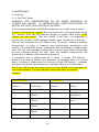
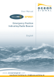
User Manual
SafeSea E100
SafeSea E100G
Emergency Position Indicating Radio Beacons
“Language”
1
The technical data, information and illustrations contained in this manual
were believed to be correct at the time of print. Ocean Signal Ltd reserve
the right to change specifications and other information contained in this
manual as part of our continual improvement process.
No part of this manual may be reproduced, stored in a retrieval system or
transmitted in any form, electronic or otherwise, without the prior
permission of Ocean Signal Ltd.
No liability can be accepted for any inaccuracies or omissions in this
manual.
Ocean Signal® and SafeSea® are registered trademarks of Ocean Signal
Ltd.
2
IN CASE OF EMERGENCY
WARNING: USE ONLY IN SITUATIONS OF GRAVE AND IMMINENT DANGER
• REMOVE THE EPIRB FROM ITS MOUNTING OR HOUSING
• TO MANUALLY ACTIVATE THE EPIRB:
NOTE: Refer to section 4.3 for deactivation instructions.
1. Break off the protective cover
2. Slide and hold the Green switch to the left, then slide the Red switch
into the down position and release the Green switch.
• REMOVE THE LANYARD COVER
• HOLDING ON TO THE FREE END OF THE LANYARD, THROW THE EPIRB
INTO THE WATER
3
CONTENTS
1 General ......................................................... 5
1.1 Introduction ............................................................. 5
1.2 Registration ..............................................................5
1.3 Programming Details ......................................................6
2 E100/E100G Overview .................................. 7
3 Installation .......................................... 8
3.1 Location ...........................................8
3.2 Float Free Housing ........................................................8
3.2.1 Loading the EPIRB .................................................9
3.3 Mounting Bracket ........................................................10
3.3.1 Loading the EPIRB ................................................10
4 Operation ...................................................... 11
4.1 Manual Activation ........................................................11
4.1.1 Deployment From an Enclosure .....................................11
4.1.2 Deployment From a Bracket ........................................12
4.1.3 Manual Activation .................................................12
4.2 Automatic Activation .....................................................13
4.3 Deactivation .............................................................14
4.3.1 Deactivation from Manual Activation ..................................14
4.3.2 Deactivation from Automatic Activation ...............................14
5 False Alerts .....................................................15
5.1 Disabling the EPIRB ......................................................15
6 Maintenance ....................................................16
6.1 Testing .................................................................16
6.1.1 Self Test Mode ....................................................16
6.1.2 GPS Test Mode ....................................................17
6.2 Inspection ..............................................................18
6.3 Battery Replacement .....................................................19
6.4 HRU Replacement .......................................................20
7 Appendix .......................................................21
7.1 System Overview .........................................................21
7.1.1 5...........................................21
7.1.2 GPS System ......................................................21
4
7.2 Specifications .......................................................... 22
7.3 Accessories ............................................................ 23
7.4 Approvals .............................................................. 23
7.5 Service & Warranty ..................................................... 24
7.6 Record of Programming Details ............................................25
5
1 GENERAL
1.1 Introduction
This manual provides valuable information for the installation, operation
and routine maintenance of both the:
SafeSea E100 EPIRB
&
SafeSea E100G EPIRB with GPS
Please read this manual completely before using your EPIRB. Parts of this
manual apply to the E100G only.
1.2 Registration
THE OWNER OF THIS 406MHz EPIRB MUST REGISTER IT WITH THE
APPROPRIATE NATIONAL AUTHORITY.
FAILURE TO REGISTER THIS EPIRB MAY RESULT IN A FINE, SLOWING
THE RESCUE PROCESS OR EVEN LOSS OF LIFE.
All 406MHz EPIRBs are programmed with a unique identity number (UIN),
which is based upon the country of registration. This is normally the
country to which the vessel is flagged.
Registration provides the Search and Rescue authorities with the correct
emergency contact details, which will speed up the rescue process.
For UK registrations go to:
www.ukshipregister.co.uk/mcga07home/emergencyresponse/mcgasearchandrescue/epirb.htm
For US registrations go to:
https://beaconregistration.noaa.gov/rgdb/
Once registration has been performed you should receive a “decal” sticker
which must be affixed to the area on the EPIRB marked “Attach proof of
registration in this area”. This decal is your proof of registration.
Useful registration contacts are:
UK EPIRB Registry
HM Coastguard (Southern)
Pendennis Point
Castle Drive
Falmouth
TR11 4WZ
6
US EPIRB Registry
NOAA/SARSAT
NSOF, E/SP3
4231 Suitland Road
Suitland, MD 20746
USA
7
This EPIRB is a radio transmitter - as such, your existing radio license
must be updated to include this EPIRB.
When an EPIRB is transferred to a new vessel, the EPIRB must be reprogrammed to include the relevant information as required by the
country controlling the new vessel.
In the US, Vessel owners should advise NOAA in writing upon change of
vessel or EPIRB ownership, transfer of EPIRB to another vessel, or any
other change in registration information.
Changing the country to which the vessel is flagged will result in the
EPIRB needing to be re-programmed, as the EPIRB UIN also contains the
country code.
It is very important that your EPIRB is registered with your National
Authority. The registration information will ensure that the rescue
authorities quickly identify the type of vessel they are searching for and
make contact to ensure the alert is not a false alarm. Although failure to
register your beacon will not stop you being rescued, it may cause
unnecessary delays and effort in the rescue centre.
1.3 Programming Details
Your EPIRB is supplied with a label titled “Programming Details”, this
contains areas where the programming details of the EPIRB can be
marked. This information includes:
1. UIN (Unique Identity Number).
2. Vessel Name.
3. MMSI.
4. Country.
5. Call Sign.
If this label has not been provided with the EPIRB information pre-inserted
then the user should write this information on the label using a UV stable
indelible pen. The UIN (15digit HEX code) can be found on the
programming certificate.
Affix the label to the left side of the EPIRB in the area provided, then place
the clear protective label provided over the first label.
It is recommended that this information is also copied into the section
provided at the back of this manual.
8
2 E100/E100G OVERVIEW
1. Strobe Lights
2. Lanyard Attachment Point
3. Programming Details Label
4. Battery Compartment
5. Test Switch
6. Indicator LED
7. Tear off tag
8. Interlock Switch
9. Activation Switch
9
3 INSTALLATION
Failure to follow the following installation guidelines may cause the EPIRB
to operate incorrectly.
Do not mount the EPIRB closer than 1 metre to any steering compass as
this may affect the accuracy of the compass.
Keep the E100 away from any strong magnetic sources such as
loudspeakers, compass compensation magnets, etc.
3.1 Location
The location selected must be sufficiently robust to support the weight of
the entire unit.
Exposure to the elements and surrounding hazards along with vibration
should also be taken into consideration when choosing the location.
Ensure that the mounting location allows easy access to the EPIRB for
maintenance and servicing.
To ensure that the EPIRB will always float free from the sinking vessel
ensure that the float free housing is located high up on the superstructure,
free from any obstructions and located in a position that it will not be
trapped, regardless of the angle the sinking vessel may be in.
Ensure that the EPIRB it is mounted with the antenna facing upwards.
3.2 Float Free Housing
Using the dimensions shown, use the four No10 x 1” screws supplied to
secure the float free housing to the chosen structure.
10
3.2.1 Loading the EPIRB
When replacing the EPIRB in the Float Free Housing please ensure that the
unit is clean and dry. The area around the activation controls and the
lanyard should be free from water and dirt to ensure reliable operation.
The EPIRB is held in place inside the Float Free Housing by the Hydrostatic
Release Module (HRU) which locks into position using a spring.
If it is necessary to replace the EPIRB into the Float Free Housing (after
maintenance or testing etc):
1. Pull the HRU back as shown (right).
2. Load the EPIRB, controls facing up, into the location seat, ensuring to
carefully fold the antenna back behind the EPIRB.
3. Gently lower the HRU back into the locked position - this also holds the
EPIRB in place.
4. Place the housing cover over the back, by placing the locating holes (on
the side of the housing) over the clips.
5. Push and rotate the housing release knob into the locked position
(right).
11
3.3 Mounting Bracket
The E100/E100G is supplied as standard with a quick release mounting
bracket. This bracket should be mounted on a suitable wall or bulkhead in
a position where it can easily be retrieved in an emergency.
Although the E100/E100G is rugged and waterproof, Ocean Signal
recommends mounting the EPIRB in a protected position whenever
possible.
Do not mount the EPIRB closer than 1 metre to any steering compass as
this may affect the accuracy of the compass.
Keep the EPIRB away from any strong magnetic sources such as
loudspeakers, compass compensation magnets, etc.
Mark the location of the four screw holes onto the mounting position. Predrill the holes
if required then screw the mounting bracket to the surface using the four
No6 x 5/8” screws supplied.
3.3.1 Loading the EPIRB
Align the back of the lanyard storage area, situated at the rear of the
EPIRB with the clip mechanism of the cradle and push into place. There
will be an audible “click” indicating that the EPIRB is now secured in place.
Do not attach the lanyard to any part of the vessel superstructure or other
part that will hinder the release of the EPIRB.
12
4 OPERATION
WARNING: USE ONLY IN SITUATIONS OF GRAVE AND IMMINENT DANGER
MISUSE MAY RESULT IN A SEVERE PENALTY
The EPIRB is designed for best operation while floating in water. If used in
other situations ensure that the EPIRB is placed in the open, clear of any
cover and kept upright. Do not place the EPIRB close to large structures or
under cover.
In the case of abandoning ship, if possible, recover the EPIRB and tie to
the survival craft or person using the lanyard. For optimum operation, it is
recommended that the EPIRB be tied to the raft with the lanyard and
floated in the sea.
4.1 Manual Activation
4.1.1 Deployment from an Enclosure
1. Push in and then rotate the housing release knob anticlockwise to
release the housing cover.
2. To remove the housing cover, tilt it, slide it sideways to free the cover
from the base clips and lift off.
3. Lift the hydrostatic release mechanism and remove the EPIRB.
13
4.1.2 Deployment from a Bracket
Press the Grey release key on the right hand side of the bracket and
remove EPIRB.
4.2 Manual Activation
Break off the clear protective cover over the Green and Red switches.
Holding the Green switch to the left, push the Red switch down and hold.
While holding the Red switch down, release the Green switch to lock the
Red switch in the active position.
The EPIRB will now be operational. The strobe lights will begin to flash at
a rate of once every 2.5 seconds as soon as the unit is activated.
For best performance it is important that the EPIRB is in an upright
position with a clear view of the sky and as far away from any metallic
structures as is possible.
If the EPIRB contains a GPS receiver, ensure that the GPS antenna is not
obstructed and has a complete, unobstructed view of the sky – as
indicated on the top of the EPIRB.
A lanyard is provided to tether the EPIRB to the lifeboat or life raft to
ensure that it does not drift away. Make sure this is firmly attached.
14
EPIRB Mode
Green Indicator
Initial EPIRB activation
On for 1 second
Acquiring GPS
position*
1 Flash every 5
seconds
Red Indicator
GPS position acquired * Flash for 1 second
121.5MHz Tx **
1 flash, with strobe
light, every 2.5
seconds
406MHz Tx
Flash for 2 seconds
406MHz Tx, with GPS
position *
Flash for 2 seconds
406MHz Tx, without
valid GPS position*
Flash for 2 seconds
* SafeSea E100G only
** The 121.5MHz homer does not begin transmission until after the first
406MHz transmission – approximately 50 seconds.
4.2 Automatic Operation
The EPIRB will sense when it has been placed in water and automatically
begin to operate, after a short delay, in the same manner as described
above
.
Note: If the EPIRB is mounted in the float free housing or on the bracket
this function is disabled until the EPIRB has been removed from either
fixture.
If the EPIRB is mounted in a float free housing, in the event that the
vessel sinks the EPIRB will automatically be ejected from the housing
allowing it to float to the surface and begin transmission.
15
4.3 Deactivation
4.3.1 Deactivation if Manually Activated
If the EPIRB has been inadvertently activated or the emergency situation
has passed, it can be turned off simply by reversing the activation
process.
Slide the Green switch to the left - the Red switch will return to the off
position. Release the Green switch.
It is not possible for the user to replace the clear protective cover. Return
the EPIRB to an Ocean Signal authorised service centre for replacement.
4.3.2 Deactivation if Automatically Activated
If the EPIRB was automatically activated, by placing in water, remove
from the water and dry. The EPIRB will automatically switch off after
approximately 30 seconds.
16
5 FALSE ALERTS
False alerts are a serious problem - they cause valuable resources to be
diverted away from real emergency situations. If a false alert is initiated,
by any means, it is important to contact the nearest search and rescue
authority and inform them of the false alert.
Report the following information:
1. EPIRB UIN.
2. Date, time and duration.
3. Cause of activation.
4. Location when the alert was activated.
5. Location at time of deactivation.
If the EPIRB was activated by mistake then turn it off. The first emergency
transmission will not occur for approximately 50 seconds, if the unit is
turned off within this time then EPIRB will not have sent an emergency
distress.
If the unit has been dropped into the water then remove from the water
and dry the case, wait approximately 30 seconds for the water contacts to
de-activate. If the unit is still flashing after this period, check that the unit
has not been manually activated; if so then follow the procedure to
manually switch the EPIRB off. The EPIRB should now be switched off,
replace the EPIRB on to the cradle or into the float free housing.
The SafeSea E100/E100G is fitted with water activation contacts. Although
the mounting bracket and float free housing are designed to prevent
accidental activation due to heavy sea or weather conditions, if the EPIRB
is not correctly fitted in it’s mounting it is possible that this may cause a
false alert situation.
5.1 Disabling the EPIRB
In the unlikely event that your EPIRB develops a fault and does not switch
off then completely disable the unit by removing the battery, as described
in section 6.3.
17
6 MAINTENANCE
6.1 Testing
6.1.1 Self Test Mode
WARNING: TEST TRANSMISSIONS ON THE HOMER FREQUENCY OF
21.5MHZ ARE LIMITED
BY INTERNATIONAL RADIO REGULATIONS TO
WITHIN THE FIRST FIVE MINUTES OF AN HOUR
It is recommended that the EPIRB is tested no more than once a month.
Activate Test Mode by rotating the grey test switch clockwise and holding
for 1 second, until the LED indicator begins to rapidly flash Green, then
release the test switch. This will initiate a self test - be prepared to
monitor the number of LED indicator flashes upon completion of the test.
The self test monitors the 121.5MHz homer RF power, initiates a satellite
transmission in order to measure key performance parameters, will
monitor the 406MHz RF power, synthesiser lock and battery voltage under
load. The self test message is designed to prevent the satellite forwarding
an alert message during self test. After the satellite transmission the
strobe light is flashed, demonstrating operation.
A successful test is determined by a series of Green LED flashes –
between one and six flashes, this sequence is repeated after a 2 second
delay. A failure is determined by a series of Red LED flashes – between
one and five flashes, this sequence is repeated after a 2 second delay.
The Green LED shows how many hours use the EPIRB has undergone on
the current battery. The Red indicator shows the failure condition.
Indicator
Green Indicator
Red indicator
No of
No of
No of
Type of
Flashes
Hours Use
Flashes
Failure
1 Flash
0 to 1hr 59min
1 Flash
121.5MHz homer
2 Flashes
2hrs
to
59min
3hrs 2 Flashes
406MHz
generation
3 Flashes
4 hrs
59min
5hrs 3 Flashes
406MHz
amp
4 Flashes
6hrs
to
59min
7hrs 4 Flashes
Replace battery
5 Flashes
8hrs
to
59min
9hrs 5 Flashes
Other failure
6 Flashes
10hrs +
to
18
power
6.1.2 GPS Test Mode
WARNING : TESTING THE GPS RECEIVER IS LIMITED TO 5 TESTS OVER
THE LIFETIME OF THE BATTERY. TESTING THE GPS RECEIVER EXPENDS
SIGNIFICANT AMOUNTS OF BATTERY ENERGY AND MAY TAKE UP TO 10
MINUTES TO COMPLETE.
THIS TEST MUST ONLY BE PERFORMED WHERE THE EPIRB HAS A CLEAR
AND UNOBSTRUCTED VIEW OF THE SKY. THIS IS REQUIRED TO ALLOW
THE GPS RECEIVER TO ACQUIRE A SIGNAL FROM SUFFICIENT
SATELLITES TO ALLOW IT TO DETERMINE A POSITION
It is recommended that this test is not performed in direct sunlight as it
may be make counting the LED flashes at the end of the test difficult. The
EPIRB must remain under observation for the whole of the test to ensure
the completion of the test is not missed.
To enter the GPS self test mode, perform the following procedure:
1. Rotate the grey test switch clockwise and hold for 1 second until the
indicator LED begins to rapidly flash Green.
2. Release the test switch and then quickly reactivate the test switch
whilst the LED is still rapidly flashing.
3. Hold the switch until the LED begins flashing Green at a slower rate;
continue to hold the test key for 5 seconds.
4. Release the switch when the LED changes from flashing Green to a
constant Red. During the test the LED will remain Red and flash Green
once every 5 seconds.
Successful test completion is indicated by the LED flashing Green for 10
seconds, with the strobe light flashing every 2.5 seconds. A test failure is
indicated by the LED flashing Red for 10 seconds with the strobe light
flashing every 2.5 seconds.
The test can be cancelled at any time by activating the Grey test switch
and holding it on for 5 seconds.
The EPIRB is limited to 5 GPS self tests, the unit will not perform any
more than this until the battery is replaced. If the GPS self test is initiated
and the EPIRB has already performed 5 GPS self tests, the indicator will
flash Red for 5 seconds and then power down. If the Grey test key is held
on after the indicator has finished flashing Red, it will then begin to rapidly
flash between Red and Green to indicate that the EPIRB power is being
held on and is needlessly draining the battery reserves.
19
GPS tests Remaining
Green LED flashes
Strobe flashes
4
4 (and then repeated)
2
3
3 (and then repeated)
2
2
2 (and then repeated)
2
1
1 (and then repeated)
2
0
Flashes for 5 seconds
2
20
6.2 Inspection
During the monthly EPIRB self test it is advised that the following
inspection is performed.
1. Inspect the EPIRB for obvious signs of damage – including the state of
the antenna; any creases in the antenna may cause the operation of the
EPIRB to be impaired.
2. Confirm that the EPIRB is securely mounted on the bracket or in the
float free housing.
3. Inspect the lanyard to ensure it is not attached to any structures.
4. Confirm the battery is within the specified expiry date.
5. If the EPIRB is housed in a float free housing confirm the HRU is within
the specified expiry date.
6. Clean the EPIRB and mounting, it is recommended that the EPIRB is
cleaned only using a damp cloth.
Other than the battery pack there are no user serviceable parts inside the
EPIRB.
DO NOT OPEN THE EPIRB, DOING SO WILL INVALIDATE THE WARRANTY
AND MAY CAUSE FALSE ALERTS
21
6.3 Battery Replacement
The EPIRB is supplied with a non-hazardous 9V Lithium battery pack. It is
recommended that this pack be replaced every 5 years, assuming that the
EPIRB has not been used for any emergency use - if the EPIRB is operated
for any purposes OTHER than the self tests, the battery should replaced to
ensure the correct operating life of the EPIRB during an emergency
situation.
If the expiry date marked on the battery pack has been reached then it
must be replaced to ensure correct operating life of the EPIRB during an
emergency situation. Always use an Ocean Signal LB2E battery to replace
the existing battery. Failure to use the correct battery may result in the
EPIRB failing to perform correctly.
For SOLAS vessels it is recommended that the battery is replaced at the
time of the Shore Based Maintenance. Batteries should only be replaced
by trained personnel with access to the required test equipment to ensure
correct operation after the battery exchange.
For non-SOLAS vessels, including recreational vessels, the user may
replace the battery themselves, or use an approved service agent.
Detailed battery replacement instructions are provided with each new
battery.
The replacement of the battery may only be performed by the end user
where it is allowed by the local or national maritime authorities.
Dispose of exhausted batteries by returning them to your service agent.
Lithium batteries require specialist methods for disposal.
DO NOT INCINERATE!
DO NOT DISPOSE OF AT SEA!
22
6.4 HRU Replacement
If you have an EPIRB mounted in a float free housing, this will also contain
a HR1E Hydrostatic Release Unit (HRU). The HRU unit must be replaced
every 2 years - the expiry date is marked on the HRU and on the front of
the housing. If this date has been reached then the HRU must be replaced
with an Ocean Signal HR1E, failure to do so may result in the HRU not
operating correctly during an emergency situation.
1. Lift the release mechanism by pulling against the spring and remove
the EPIRB from the housing.
2. Push the HRU down against the spring and remove the locking pin.
Carefully remove the HRU from the spring.
3. Using the new HRU, locate the two retaining ridges (at the bottom of
the HRU) onto the spring. Carefully push the HRU against the spring.
4. Push the HRU into position as shown. Push the locking pin home with
the retaining flange pointing down. Load the EPIRB into the housing.
23
7 APPENDIX
7.1 System Overview
7.1.1 COSPAS/SARSAT System
The COSPAS/SARSAT system utilises two satellite arrays to provide
distress alert and location data to search and rescue authorities.
The GEOSAR system can provide near immediate alerting within the
coverage of the receiving satellite.
The LEOSAR system provides coverage of the polar region beyond the
range of the GEOSAR system. It can calculate the location of distress
events using Doppler processing techniques and is less susceptible to
obstructions which could block a signal in a given direction.
The system is comprised of instruments on board the satellites which
detect the signals from the distress beacons. Ground receiving stations,
referred to as Local Users Terminals (LUTs) receive and process the
satellite downlink signal to generate the distress alerts. The distress
alerts, generated by the LUTs, are then received by Mission Control
Centres (MCCs) which then forward the alert to Rescue Co-ordination
Centres (RCCs), Search and Rescue Points of Contacts (SPOCs) and other
MCCs.
7.1.2 GPS System
The GPS system is a satellite array that enables a GPS receiver to
determine its position around the globe. There are a minimum of 24
satellites orbiting the Earth providing accurate position, velocity and time
information.
The SafeSea E100G has a built in 50 channel GPS receiver and antenna
allowing reception of this positional data. The received position is then
coded into the EPIRB emergency transmission thus enabling search and
rescue teams to narrow the search area and increase the effectiveness of
the rescue operation.
24
7.2 Specifications
406Mhz Transmitter
Frequency .................................406.037 MHz ±1KHz
Output Power ...............................5W Typical
Modulation .................................Phase ±1.1 Radians Pk
(16K0G1D)
Encoding ..................................Biphase L
Duration ...................................520mS
Frequency Stability ..........................2 parts per billion / 100mS
Rate ......................................400 bps
121.5MHz Transmitter
Frequency .................................121.5 MHz
Output Power ...............................25-100mW PEP
Modulation .................................Swept Tone AM (3K20A3X)
Sweep Range / Rate .........................375-1125 Hz
Modulation Depth ...........................96%
Frequency Stability ..........................±50ppm
Duty Cycle .................................40%
Low Duty Cycle Strobe
Light Type .................................Two High Intensity LEDs
Light Colour ................................White
Output Power ...............................0.75 dc effective candela
Flash Rate .................................20-30 per minute
Battery
Type ......................................Lithium Manganese Dioxide
(LiMnO2)
Operating ..................................Typically 96Hours
Replacement Interval ........................5 years
GPS Receiver (Safesea E100G only)
Satellites Tracked ...........................50 Channel Engine
Sensitivity ..................................-146dBm
Cold Start Re-acquisition ....................-162dBm
Centre Frequency ...........................1.57524 GHz
GPS Antenna ...............................Microstrip Patch
25
General
Height of Body ..............................212mm
Maximum Body diameter .....................110mm
Weight ....................................735grams
Environmental
IEC60945 Category ..........................Portable
Operating Temperature ......................Class 2 -20C to +55C
Storage Temperature ........................Class 2 -30C to +70C
Automatic release depth .....................4 metres maximum
Waterproof .................................Exceeds 10m at 20°C
26
7.3 Accessories
Replacement Lithium Battery for E100/E100G ............LB2S
7.4 Approvals
Cospas-Sarsat ...............T.001/T.007
Europe ......................Marine Equipment Directive MED A.1/5.6
IEC 61097-2
IEC 60945
USA ........................USCG/FCC Approved
FCC ID: XYEE100
Worldwide ...................IEC 61097-2
IMO Regulations ..............A.662(16)
A.694(17)
A.810(19)
A.814(19)
27
7.5 Service & Warranty
All servicing or repairs of this EPIRB must be carried out by an approved
service agent.
See section 8 for warranty conditions.
Please retain the original packaging for your EPIRB. If the EPIRB has to be
returned, for any reason, the original packaging should be used.
The battery packs used with this EPIRB are classed as non-hazardous
under IATA Hazardous Transport Regulation.
• Batteries should be shipped as category 3090, packing instruction 968:
part 2.
• EPIRBs with batteries should be shipped as category 3091, packing
instruction 969: part 2. (The battery should be removed from the EPIRB
before packing, but can be in the same box.)
Your SafeSea E100/E100G EPIRB is warranted against manufacturing
defects in materials and workmanship for a period of two years from date
of purchase. Ocean Signal Ltd will, at its discretion, repair or replace a
faulty product free of charge, including return carriage costs to the owner.
For further assistance, please contact our Technical Service Department:
Email: [email protected]
Accidental damage and misuse or non-approved modifications are not
covered by this warranty. This warranty does not affect your statutory
rights.
Dealer Stamp:
Date of Purchase: .............................................................
28
7.6 Record of Programming Details
It is recommended that the information entered on the Programming
Details label on the EPIRB is also copied here for future reference.
UIN: ..............................................
VESSEL NAME: ..............................................
MMSI: ..............................................
COUNTRY: ..............................................
CALL SIGN: ..............................................
29